Table of Contents
Advertisement
Quick Links
Advertisement
Table of Contents
Troubleshooting

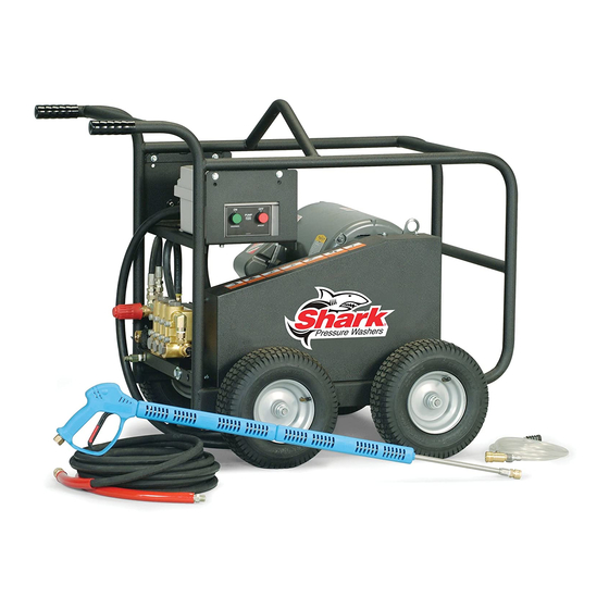
Summary of Contents for Shark BDE-505009B
- Page 1 SERVICE MANUAL ® MODEL # ORDER # BDE-505009B 1.107-085.0 BDE-505009C 1.107-086.0 MPE5-50024B 1.106-001.0 MPE5-50024C 1.106-002.0 HD 5.0/50 Eb CAGE 1.107-084.0 HD 5.5/50 Ec CAGE 1.107-087.0 BRE-505007B 1.106-060.0 BRE-505007C 1.106-059.0 9.800-415.0...
-
Page 2: Table Of Contents
CONTENTS Exploded View ....................4 Exploded View, Parts List ................5-6 Electrical Box Exploded View andParts List ..........7 VBA Unloader ....................8 Hose & Spray Gun AssemblyTroubleshooting ..........9 H Series Pump Exploded View and Parts List ........10-11 Troubleshooting ..................12 230 VCA Electric Diagram ................13 460 VCA Electric Diagram ................14 Model Number ______________________________ Serial Number ______________________________... -
Page 3: Exploded View
EXPLODED VIEW 12,15 9.800-415.0 • Rev. 06/14... -
Page 4: Exploded View Parts List
EXPLODED VIEW PARTS LIST ITEM PART NO. DESCRIPTION ITEM PART NO. DESCRIPTION 8.932-965.0 Label, Warning-Exposed 9.803-810.0 Nozzle, SAQCMEG 0004.5, 1 Pulleys 9.803-811.0 Nozzle, SAQCMEG 15045, 1 9.803-842.0 Label, Operating Instr. Yellow (Lexan) 9.803-812.0 Nozzle, SAQCMEG 25045, 1 9.803-993.0 Label, Relieve Pressure Green 9.803-994.0 Label, Equipment Operated 1... - Page 5 EXPLODED VIEW PARTS LIST ITEM PART NO. DESCRIPTION ITEM PART NO. DESCRIPTION 9.802-259.0 Hose, 1/2" Push-On 15" 9.802-803.0 Washer, 1/4" Flat, SAE, Black Zinc 9.803-992.0 Cord, Service 4/4 37" (230V/3PH) 9.802-804.0 Washer, 5/16" Flat, SAE 9.802-437.0 Cord, Service 10/4 37" 9.802-807.0 Washer, 3/8"...
-
Page 6: Electrical Box Exploded View Andparts List
EXPLODED VIEW - ELECTRICAL BOX 9.800-415.0-3 ELECTRICAL BOX PARTS LIST ITEM PART NO. DESCRIPTION ITEM PART NO. DESCRIPTION 8.900-315.0 Label, On/Off, PE Push 9.803-974.0 Switch, Green PB, CH Buttons E22PB3 9.800-016.0 Label, Disconnect Power 9.803-973.0 Switch, Red PB, CH E22EB2 1 Supply 8.724-284.0 Contactor 1 (230V/3PH) -
Page 7: Vba Unloader
VB UNLOADER EXPLODED VIEW 9.802-360.0 VB350/4 10.5 GPM at 5100 PSI VB UNLOADER EXPLODED VIEW PARTS LIST ITEM PART # DESCRIPTION ITEM PART # DESCRIPTION 3/8 Bsp F Nipple VB280-350 Val. Pist. Seal O-Ring, 1.78 x 15.6 mm M8 Piston Spring Sst 11/32"... -
Page 8: Hose & Spray Gun Assemblytroubleshooting
HOSE & SPRAY GUN ASSEMBLY 9.800-415.0-4 HOSE & SPRAY GUN ASSEMBLY PARTS LIST ITEM PART NO. DESCRIPTION ITEM PART NO. DESCRIPTION 9.802-228.0 Gun w/Wand (5000 PSI), 9.802-251.0 Hose, 1/4" x 1/2" w/Coupler Clear Vinyl 6 ft. 8.739-346.0 Hose, 3/8" x 50', 2 Wire, TS KA, 9.802-160.0 Strainer, Plastic, 1/4"... -
Page 9: H Series Pump Exploded View And Parts List
H-SERIES PUMP EXPLODED VIEW TORQUE SPECS ITEM # FT. LBS. H-SERIES PUMP EXPLODED VIEW PARTS LIST ITEM PART NO. DESCRIPTION ITEM PART NO. DESCRIPTION 9.803-163.0 Crankcase 9.802-890.0 Lock Washer 9.803-195.0 Plunger Guide 9.803-198.0 Copper Washer 3/8 See Kit Below Plunger Oil Seal 9.802-925.0 Brass Plug 3/8 See Kits Below... - Page 10 H-SERIES PUMP EXPLODED VIEW PARTS LIST ITEM PART NO. DESCRIPTION 9.803-188.0 O-Ring Ø1.78x7.66 9.803-155.0 Tefl on Ring See Kit Below Plunger 18mm 9.802-888.0 Copper Spacer 9.803-294.0 Plunger Rod 9.803-157.0 Connecting Rod 9.802-912.0 Snap Ring 9.802-915.0 Connecting Rod Pin 9.802-889.0 Spring Washer 9.802-937.0 Connecting Rod Screw 9.803-194.0...
-
Page 11: Troubleshooting
TROUBLESHOOTING PROBLEM POSSIBLE CAUSE SOLUTION PUMP RUNNING Pump sucking air Check water supply and possibility of air NORMALLY BUT seepage. PRESSURE LOW Check valves sticking Check and clean or replace if necessary. ON INSTALLATION Unloader valve seat faulty Check and replace if necessary. Nozzle incorrectly sized Check and replace if necessary. -
Page 12: 230 Vca Electric Diagram
230 VCA ELECTRIC DIAGRAM 9.800-415.0 • Rev. 06/14... -
Page 13: 460 Vca Electric Diagram
460 VCA ELECTRIC DIAGRAM 9.800-415.0 • Rev. 06/14... - Page 14 Form #9.800-415.0 • Revised 06/14 • Printed in U.S.A. or Mexico...


Need help?
Do you have a question about the BDE-505009B and is the answer not in the manual?
Questions and answers