Table of Contents
Advertisement
Advertisement
Table of Contents

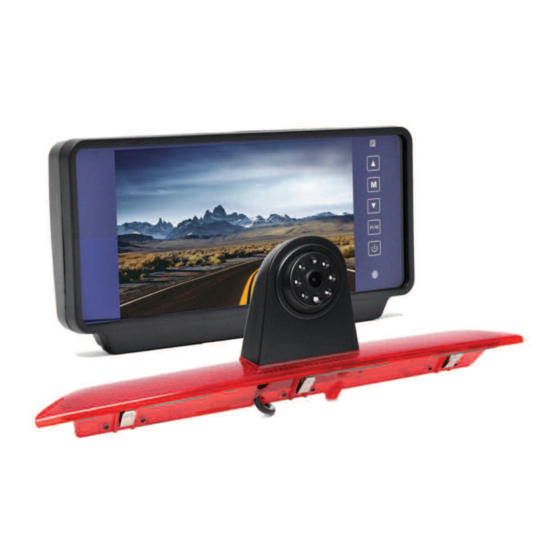
Summary of Contents for Rear view safety RVS-920619
-
Page 2: Table Of Contents
Table of Contents Introduction ....................3 Safety Information ..................4-6 Before Beginning Installation..............7 Installation Guide..................8 Wiring Camera & Monitor..............9-10 Replacement Installation Diagram............11 Clip-On Installation Diagram ..............12 Installing The Monitor................13 Monitor Operation ................... Splitting & Splicing ...................15 Positioning ....................16 Multiplexer ....................17 Monitor Dimensions..................18 Monitor Specifications................19 Troubleshooting..................20... -
Page 3: Introduction
Introduction Please read all of the installation instructions carefully before installing the product. Improper installation will void manufacturer’s warranty. Congratulations on purchasing a Rear View Backup Camera System! With this manual you will be able to properly install and operate the unit. The Backup Camera System is intended to be installed as a supplement aid to your standard rear view mirror that already ex- ists in your vehicle. -
Page 4: Safety Information
Rear View Camera System is backing up, in the same way limited. It does not display as you would if the vehicle the entire panorama that is did not have the Rear View behind you. REAR VIEW SAFETY... - Page 5 Safety Information INSTALLATION • While installing the RVS System be careful with the • Electric shock or product wire positioning in order to malfunction may occur if avoid wire damage. this product is installed incorrectly. • The RVS System should only be used when the •...
- Page 6 Safety Information If you have questions about this product, contact: Customer Service: Rear View Safety 1797 Atlantic Avenue Brooklyn, NY 11233 Tel: 1.800.764.1028 IN NO EVENT SHALL SELLER OR MANUFACTURER BE LIABLE FOR ANY DIRECT OR CONSEQUENTIAL DAMAGES OF ANY NATURE, OR LOSSES OR EXPENSES RESULTING FROM ANY DEFECTIVE PRODUCT OR THE USE OF ANY PRODUCT.
-
Page 7: Before Beginning Installation
Before You Begin Installation Before drilling please check that no cable or wiring is on the other side of the wall. Please clamp all wires securely to reduce the possibility of them being damaged while vehicle is in use. Keep all cables away from hot or moving parts and electrical noisy components. -
Page 8: Installation Guide
1. The Mirror Monitor attaches to the existing rear view mirror in vehicle with the pressurized clips on the back of the monitor. 2. Attach monitor to existing miror, and adjust mounting angle to allow optimum driver viewing comfort. (see figure 1.1 on page 12). REAR VIEW SAFETY... -
Page 9: Wiring Camera & Monitor
Wiring Camera & Monitor The multiplexer. larly be triggered (i.e. side cam- eras can be triggered by the turn • To power the system connect signals etc.) the power (RED) 12V+ wire to ignition power and the ground • To automatically have camera (BLACK) wire to chassis ground. -
Page 10: Wiring Camera & Monitor
ON and therefore can pushing the power button on drain battery. Therefore it is monitor. This is in addition to recommended to connect utilizing the positive triggers. power to an ignition switched accessory power source. REAR VIEW SAFETY... -
Page 11: Replacement Installation Diagram
Replacement Installation Diagram Replacement Monitor Figure 1.1 Figure 1.2 Figure 1.3 Reverse With Confidence ™... -
Page 12: Clip-On Installation Diagram
Clip-On Installation Diagram Clip-On Monitor Figure 1.1 Figure 1.2 Figure 1.3 REAR VIEW SAFETY... -
Page 13: Installing The Monitor
Installing the Monitor 66ft Extension Cable Monitor Optional Video Out Camera Available -3 Amp Fuse 1. DC12V-24V (red) 2. Ground (black) 3. Port #3 (blue) 4. Port #2 (white) 5. Port #1 (yellow) Reverse With Confidence ™... -
Page 14: Monitor Operation
• Trigger source: Change the channel destination for each trigger. • Trigger delay: Adjust the delay time on each trigger. • Distance Grid: Choose what channel the distance grid will display on. • Grid Position: Move the grid-lines. • Reset: Reset all settings to factory default. REAR VIEW SAFETY... -
Page 15: Splitting & Splicing
Splicing 1. Red - Power (+) 2. Yellow - Video 3. Green - Mirror / Normal Imaging 4. White - Audio 5. Black - Ground (-) Reverse With Confidence ™... -
Page 16: Positioning
Positioning General Installation Location REAR VIEW SAFETY... -
Page 17: Multiplexer
Multiplexer Port #1 Port #2 Port #3 or DVD Backup Reverse With Confidence ™... -
Page 18: Monitor Dimensions
Monitor Dimensions Replacement Monitor Clip-On Monitor REAR VIEW SAFETY... -
Page 19: Monitor Specifications
Monitor Specifications TFT LCD Digital Monitor Screen Size Digital 7” Dot Resolution x 3 (RGB) x 480 Display Format 16:9 Display Brightness 400cd/m Viewing Angle 90° min Video Input 3 channel Video Source 1Vp-p, 75 Power Supply DC 12V-24V (+/-10%) Power Consumption Operating Temperature -10°C - +65°... -
Page 20: Troubleshooting
Verify Blue trigger is receiving monitor power • Verify camera is connected to cable Audio on Camera (optional) Verify chosen camera has audio Confirm that the Blue audio • • Verify volume setting trigger is connected to 12v+ • REAR VIEW SAFETY... -
Page 21: Warranty
Rear View Safety Inc. system after partial failure or use with im- proper accessories. -
Page 22: Disclaimer
In no event shall Rear View Safety and/or its affiliates have any liability for any losses (whether direct... - Page 23 Take Notes Reverse With Confidence ™...
- Page 24 If you have any questions about this product, contact: Rear View Safety, Inc. 1797 Atlantic Avenue Brooklyn, NY 11233 800.764.1028 BETTER CAMERAS. BETTER SERVICE. IT’S OUR GUARANTEE.


Need help?
Do you have a question about the RVS-920619 and is the answer not in the manual?
Questions and answers