Table of Contents
Advertisement
Advertisement
Table of Contents

Related Manuals for Rear view safety RVS-770613-213


Summary of Contents for Rear view safety RVS-770613-213
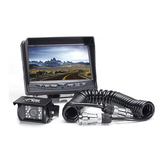
- Page 2 • 1 7" LED Digital Panel color rear view monitor with universal mount/stand • 1 Trailer quick connect/disconnect kit • 1 Remote control • 1 Power connection wire • 1 Double RCA + power converter (to connect external audio, video and power) • 1 Screw kit for installation REAR VIEW SAFETY...
-
Page 3: Table Of Contents
Table of Contents Introduction ....................4 Safety Information ..................5-7 Before Beginning Installation..............8 Installation Guide..................9 Wiring Camera & Monitor..............10-11 Installation Diagram .................12 Installing the Monitor ................13 Monitor Operation..................14 Splitting & Splicing ...................15 Positioning....................Troubleshooting..................17 Monitor Dimensions..................18 Monitor Specifications................19 Camera Dimensions...................20 Camera Specifications ................21 Reverse With Confidence ™... -
Page 4: Introduction
In some jurisdictions, it is unlawful for a person to drive a motor vehicle equipped with a TV viewer or screen located forward of the back of the driver’s seat or in any location that is visible, directly or indirectly, to the driver while operating the vehicle. REAR VIEW SAFETY... -
Page 5: Safety Information
Safety Information Please read the entire manual and follow the instructions and warnings carefully. Failure to do so can cause serious damage and/or injury, including loss of life. Be sure to obey all applica- ble local traffic and motor vehicle regulations as it pertains to this product. - Page 6 Dropping the unit may cause is detected, disconnect the possible mechanical failure. system immediately. • Where the power cable may touch a metal case, cover the cable with a friction tape. A short circuit or disconnected wire may cause a fire. REAR VIEW SAFETY...
- Page 7 Safety Information IN NO EVENT SHALL SELLER OR MANUFACTURER BE LIABLE FOR ANY DIRECT OR CONSEQUENTIAL DAMAGES OF ANY NATURE, OR LOSSES OR EXPENSES RESULTING FROM ANY DEFECTIVE PRODUCT OR THE USE OF ANY PRODUCT. Reverse With Confidence ™...
-
Page 8: Before Beginning Installation
Install split grommets where applicable Step 3: Once all cables and wiring have been properly placed routed, perform a system function test by temporarily connecting he system. If the system seems to not be operating properly see troubleshooting (page 17) REAR VIEW SAFETY... -
Page 9: Installation Guide
Installation Guide Camera 1. Attach camera bracket close to rear marker lights, centered on vehicle (Figure 1.5 number 5). 2. Attach camera to bracket using screws provided and adjust the angle. Cable + Quick Connect/Disconnect Kit 1. The cable on this system is split into three parts, two camera cables that end with Quick Connect terminals and a Pigtail Cable. -
Page 10: Wiring Camera & Monitor
Camera: Drill a 20mm (0.8in) drain battery. Therefore it is diameter hole into vehicle recommended to connect body near the camera and power to an ignition switched bracket. Insert camera cable into accessory power source. vehicle (be careful not to kink REAR VIEW SAFETY... -
Page 11: Wiring Camera & Monitor
Wiring Camera & Monitor • Audio works on two ports, ports • When installing all THREE (3) 2 and 3. The blue trigger for cameras, use all three ports and port 3 must be activated (12V) connect all positive triggers to for the sound. -
Page 12: Installation Diagram
Installation Diagram Figure 1.1 Figure 1.2 Figure 1.3 Figure 1.4 Connection of Connection of U Flushmount Bracket Bracket REAR VIEW SAFETY... -
Page 13: Installing The Monitor
Installing the Monitor Figure 1.5 1. Monitor 2, 3, 4. Trailer Connect/Disconnect Cable 5. Camera Reverse With Confidence ™... -
Page 14: Monitor Operation
Grid Position: Adjust grid lines • Auto Power: On: Monitor will automatically turn on when powered. Off: Monitor will only turn on when triggered. Auto: Monitor will follow previous state. • Reset: Reset settings to factory default REAR VIEW SAFETY... -
Page 15: Splitting & Splicing
Splitting & Splicing Installing sun shield: Put shade cover on the display. Installing back cover: Put the monitor with shade cover in the back cover (only for embedded monitor) Splitting back cover: Hold monitor with 2 hands and detach with fingers, as indicated by arrows. -
Page 16: Positioning
Positioning REAR VIEW SAFETY... -
Page 17: Troubleshooting
Troubleshooting Monitor Displays Blue Screen & Displays No Signal • Do a hard reset, unplug all trigger on power harness is cables and power cables and put to power 12v+. leave them out for 1 minute If the problem still persists, ver- and then re-connect them. -
Page 18: Monitor Dimensions
Monitor Dimensions 7” 5 25” Rotation Imager Menu/ Camera (Exit in Down Power Selection Menu Selection Arrow Arrow On/Off Button Mode) power video select down/up menu mirror/ normal image REAR VIEW SAFETY... -
Page 19: Monitor Specifications
Monitor Specifications LED Digital Monitor Screen Size 7” Dot Resolution x 3 (RGB) x 480 Display Format 16:9 / 500:1 Display Brightness 400cd/m Viewing Angle U:50° / D:60° / R:70° Video Input 3 channel Video Source 1Vp-p, 75 Power Supply DC 9V-32V Power Consumption Operating Temperature... -
Page 20: Camera Dimensions
Camera Dimensions 3” 3 25” REAR VIEW SAFETY... -
Page 21: Camera Specifications
Camera Specifications Camera 1/3” Sharp® Color CCD Picture Elements 410,000 pixels r=0.45 to 1.0 Gamma Correction 620 TVL NTSC 811H x Image Sensor 507 V, PAL 752H x 582V Lens 2.5mm View Angle 130° Sync System Internal Synchronization Infrared distance 50 Feet (18 Infrared IR) Usable Illumination 0 Lux (IR On)
Need help?
Do you have a question about the RVS-770613-213 and is the answer not in the manual?
Questions and answers
I have blue light but nothing on the screen. What could be the problem