
Related Manuals for SICK ICR 84x


Summary of Contents for SICK ICR 84x
- Page 1 O P E R AT I N G I N S T R U C T I O N S ICR 84x Image Code Reader Scanner family for reading 1-D and 2-D codes...
-
Page 2: Software Versions
V 4.2 P658 CLV Setup Help Online help (HTML) V 4.2 P658 The ICR 84x is exclusively intended for use in an industrial environment. In case of use in residential areas, RF interference may occur. Copyright Copyright © 2005 SICK AG Waldkirch... - Page 3 Page 6-4 • Troubleshooting – Chapter 8 “Troubleshooting“, Page 8-1 • Finding information – Table of contents, Page I-5 Chapter 10.14 “Index“, Page 10-52 – © SICK AG · Division Auto Ident · Germany · All rights reserved 8 010 961/0000/10-05-2005...
- Page 4 ICR permanently and save the parameter set as an "*.scl" configuration file in CLV Setup. The ICR can now be operated with the application-specific settings. © SICK AG · Division Auto Ident · Germany · All rights reserved 8 010 961/0000/10-05-2005...
-
Page 5: Table Of Contents
Installing the incremental encoder ................4-10 Removing the device......................4-10 Electrical installation ....................5-1 Overview of the installation sequence................5-1 5.1.1 SICK Connection Modules (Overview) ................. 5-1 © SICK AG · Division Auto Ident · Germany · All rights reserved 8 010 961/0000/10-05-2005... - Page 6 Overview of errors and malfunctions which could occur ..........8-1 8.1.1 Installation errors ........................8-1 8.1.2 Electrical connection errors ....................8-1 8.1.3 Parameterization errors......................8-1 8.1.4 Malfunctions during operation..................8-1 © SICK AG · Division Auto Ident · Germany · All rights reserved 8 010 961/0000/10-05-2005...
- Page 7 Accessories ........................10-40 10.9.1 Installation accessories ....................10-40 10.9.2 Connection modules..................... 10-40 10.9.3 Extensions for connection modules................ 10-41 10.9.4 Cables and plug-in connections ................10-42 © SICK AG · Division Auto Ident · Germany · All rights reserved 8 010 961/0000/10-05-2005...
- Page 8 10.12 Glossary ............................10-45 10.13 EC Declaration of Conformity....................10-51 10.14 Index............................10-52 10.15 Code samples.........................10-57 10.15.1 1-D and 2-D code samples for ICR 840 (standard type).......10-57 © SICK AG · Division Auto Ident · Germany · All rights reserved 8 010 961/0000/10-05-2005...
- Page 9 Error message output to the auxiliary interface.............8-2 Table 8-2: Meaning of the ST error status in the reading result...........8-3 Table 8-3: Troubleshooting: Restoring operation (Reading mode)........8-5 © SICK AG · Division Auto Ident · Germany · All rights reserved 8 010 961/0000/10-05-2005...
- Page 10 2-D code sample (DataMatrix ECC200; cell size 0.3 mm (11.8 mil)) ..6-3 Fig. 6-2: Bar code sample (code 39; module width 0.35 mm (13.8 mil); print ratio 2:1)........................6-3 © SICK AG · Division Auto Ident · Germany · All rights reserved I-10 8 010 961/0000/10-05-2005...
- Page 11 Fig. 10-1: CLV Setup: Results of the AutoBaud detect function ........10-7 Fig. 10-2: User interface of the “CLV Setup“ software ............10-8 © SICK AG · Division Auto Ident · Germany · All rights reserved I-11 8 010 961/0000/10-05-2005...
- Page 12 Copy of the Declaration of Conformity (Page 1, scaled down)....10-51 Fig. 10-24: Scannable 1-D codes with various module widths (print ratio 2:1)/ 2-D code...........................10-57 © SICK AG · Division Auto Ident · Germany · All rights reserved I-12 8 010 961/0000/10-05-2005...
-
Page 13: Notes On This Document
Exchanging the device while retaining the parameter set • Special applications and procedures The ICR 84x Image Code Reader with all its variants is simply referred to as “ICR“ in the document, except where a distinction is necessary. Target audience This document is intended for persons who are responsible for the following activities: 1.2.1... -
Page 14: Symbols
This symbol identifies single-step instructions. An action must be performed. Instructions consisting of several steps are numbered consecutively. Here you select a function of the user interface of CLV Setup. © SICK AG · Division Auto Ident · Germany · All rights reserved 8 010 961/0000/10-05-2005... -
Page 15: Safety Information
Ethernet) to a host for further processing. Any warranty claims vis-à-vis SICK AG will be rendered invalid if the device is used for any other purpose or if changes are made to the device, also as part of the installation and electrical installation procedures. -
Page 16: General Safety Precautions And Protection Measures
2.3.1 RF interferences The ICR 84x is exclusively intended for use in an industrial environment. In case of use in residential areas, RF interference may occur. 2.3.2 Electrical installation... -
Page 17: Quick Stop And Quick Restart
Switch on the supply voltage or reattach cable plug of the ICR to the connection module. The ICR resumes operation with the last permanently stored parameter set and resets the daily operating data. © SICK AG · Division Auto Ident · Germany · All rights reserved 8 010 961/0000/10-05-2005... -
Page 18: Environmental Information
(electronic scrap) (see Chapter 7.3 “Disposal“, Page 7-2). At present SICK AG does not take back devices which have become unusable or irreparable. © SICK AG · Division Auto Ident · Germany · All rights reserved 8 010 961/0000/10-05-2005... -
Page 19: Product Description
(HTML files) – "CLV-Connect" PC software (HTML files showing terminal diagrams) – ICR 84x Operating Instructions in English and German as PDF edition as well as additional publications (connections module, other SICK bar code scanners) – freely available "Acrobat Reader" PC software for reading PDF files... -
Page 20: System Requirements
System requirements The following are required to start up and operate the ICR: Electrical connecting: 1. A SICK connection module for power supply of the ICR (15 to 30 V DC) and connection of the data and functional interfaces. Available types: –... -
Page 21: Product Features And Functions (Overview)
Alternatively with simple command strings, also for use with special devices • Four status LEDs • Beeper to confirm device functions or operating steps (can be switches off) © SICK AG · Division Auto Ident · Germany · All rights reserved 8 010 961/0000/10-05-2005... - Page 22 • Serial terminal interface (RS 232) as auxiliary data interface with fixed transfer rate and fixed protocol • CAN interface for integration in the SICK CAN scanner network or a CANopen network • Ethernet interface with TCP/IP or FTP •...
-
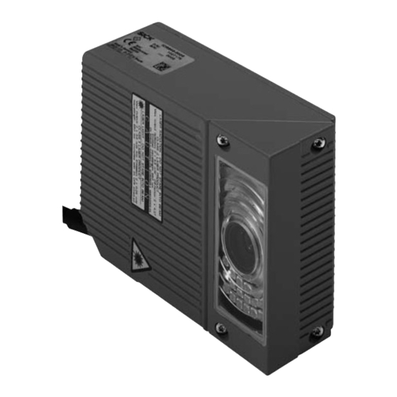
Page 23: View Of The Device
RJ 45 10baseT socket for Ethernet connection with LEDs Sound opening of the beeper (covered) LEDs (status indicators) Laser warning labels Connection cable Fig. 3-1: Design of the ICR © SICK AG · Division Auto Ident · Germany · All rights reserved 8 010 961/0000/10-05-2005... -
Page 24: Method Of Operation
Path increment e.g. Good Read Teach-in match code 1 e.g. No Read End of reading interval Fig. 3-3: Block diagram: functions of the ICR © SICK AG · Division Auto Ident · Germany · All rights reserved 8 010 961/0000/10-05-2005... - Page 25 Alternatively, the Ethernet interface is available for both types of operation. The ICR outputs system and error messages as error codes, which can be requested from the error memory using command strings. © SICK AG · Division Auto Ident · Germany · All rights reserved 8 010 961/0000/10-05-2005...
-
Page 26: Indicators And Control Elements
3-4) are located on the rear of the device toward the bottom. Table 3-2, Page 3-9 shows the meaning of the LEDs in the different operating modes/functions. Fig. 3-4: LEDs © SICK AG · Division Auto Ident · Germany · All rights reserved 8 010 961/0000/10-05-2005... -
Page 27: Table 3-2: Meaning Of The General Leds
Data Yellow Lights up when the ICR receives or sends addressed data via Ethernet Table 3-3: Meaning of the LEDs of the Ethernet interface © SICK AG · Division Auto Ident · Germany · All rights reserved 8 010 961/0000/10-05-2005... -
Page 28: Function Of The Beeper
5. Confirm the dialog box by selecting the P save option. ERMANENT The ICR operates the beeper with the values selected for the function of the result status. © SICK AG · Division Auto Ident · Germany · All rights reserved 3-10 8 010 961/0000/10-05-2005... -
Page 29: Installation
ICR) 4.2.3 Laying out the required tools • Two M5 screws for fastening the SICK mounting bracket (strength: 8 mm (0.31 in)) to the installation base. The screw length depends on the wall thickness of the base • Tool •... -
Page 30: Selecting The Installation Site
(32.8 ft) from the ICR, since the “CLV Setup“ program on the PC accesses the auxiliary interface of the ICR via this module (RS 232) by default. © SICK AG · Division Auto Ident · Germany · All rights reserved 8 010 961/0000/10-05-2005... -
Page 31: Mounting Accessories
ICR installation options using the mounting bracket no. 2 025 491 The dimensions of the mounting bracket are shown in Chapter 10.10 “Dimensional drawings of the accessories“, Page 10-43. © SICK AG · Division Auto Ident · Germany · All rights reserved 8 010 961/0000/10-05-2005... -
Page 32: Distance Between Icr And Code
The size of the available reading area (surface), which is mapped in sharp focus by the ICR in its image memory, depends on the reading distance. See Fig. 9-4, Page 9-5. © SICK AG · Division Auto Ident · Germany · All rights reserved 8 010 961/0000/10-05-2005... -
Page 33: Table 4-1: Permissible Reading Angle Between The Reading Area And The Bar Code/2-D Code When Reading With Omni-Directional Decoder
The length of readable bar code is reduced with respect to the decodable length as a result of the distance-dependent dimensions of the reading area (surface) (see examples in Table 9-2, Page 9-2). © SICK AG · Division Auto Ident · Germany · All rights reserved 8 010 961/0000/10-05-2005... -
Page 34: Count Direction Of The Code Position Cp
When the ICR 840 is in the focus position (reading distance 80 mm ((3.15 in)), one pixel in the image memory is approx. 33 µ, whereby 1% of the CP is approx. 0.4 mm lengthwise of the reading area. © SICK AG · Division Auto Ident · Germany · All rights reserved 8 010 961/0000/10-05-2005... - Page 35 The ICR outputs the PT or CP value for each code in the reading result via the host interface. The values are always multi-digit numbers located in the selected position in the reading data. © SICK AG · Division Auto Ident · Germany · All rights reserved 8 010 961/0000/10-05-2005...
-
Page 36: Installing And Adjusting The Device
4-6). 7. Mark the bracket of the ICR on the base (supporting stand), drill the required holes and install the bracket on the base. © SICK AG · Division Auto Ident · Germany · All rights reserved 8 010 961/0000/10-05-2005... -
Page 37: Installing External Components
RS 232 data cable (null modem cable) to the internal 9-pin “Aux“ plug of the module. (see Chapter 5.5.7 “Connecting the PC“, Page 5-12). © SICK AG · Division Auto Ident · Germany · All rights reserved 8 010 961/0000/10-05-2005... -
Page 38: Installing The Incremental Encoder
When removing the device from service for the last time, please dispose of it in an environmentally-friendly manner, as described in Chapter 7.3 “Disposal“, Page 7-2. © SICK AG · Division Auto Ident · Germany · All rights reserved 4-10 8 010 961/0000/10-05-2005... -
Page 39: Electrical Installation
• Power supply All of the connections must be wired with copper cables with a minimum wire diameter of 0.09 mm (approx. 17 AWG)! © SICK AG · Division Auto Ident · Germany · All rights reserved 8 010 961/0000/10-05-2005... -
Page 40: Pre-Fabricated Cables (Overview)
– – cable if necessary 15 to 30 V DC Fig. 5-1: Block diagram: Connection of the ICR to the CDB 420 or CDM 420 Connection Module © SICK AG · Division Auto Ident · Germany · All rights reserved 8 010 961/0000/10-05-2005... - Page 41 CMF 400 Bus Modules (field bus gateways) for connecting the CLV to Profibus DP or DeviceNet For detailed descriptions about functions and installation see the corresponding Fitting/ Operatings Instructions (see Chapter 10.11 “Supplementary documentation“, Page 10-44). © SICK AG · Division Auto Ident · Germany · All rights reserved 8 010 961/0000/10-05-2005...
-
Page 42: Pin Assignments
Transmitter+ TX– Transmitter– Receiver+ RX– Receiver– 4, 5, 7, 8 n.c. Not connected Table 5-4: Pin assignment of the 8-pin RJ 45 10baseT socket © SICK AG · Division Auto Ident · Germany · All rights reserved 8 010 961/0000/10-05-2005... -
Page 43: Electrical Installation Preparations
Table 5-6: Power-up delay as a function of the device number GN The device number can be selected on the D tab in the CLV Setup EVICE ONFIGURATION program. © SICK AG · Division Auto Ident · Germany · All rights reserved 8 010 961/0000/10-05-2005... -
Page 44: Non-Sick Power Supply Unit/Connections Without The Sick Connection Module
Non-SICK power supply unit/connections without the SICK connection module If a non-SICK power supply unit is used instead of the CDB 420 or CDM 420, it must provide a functional extra-low voltage in accordance with the standard IEC 364-4-41 and a continuous power output of at least 12 W. -
Page 45: Performing Electrical Installation
Connect the power supply to the red wire (pin 1, +V ) and the black wire (pin 5, GND) of the cable no. 6 010 137 (see also Table 5-7). © SICK AG · Division Auto Ident · Germany · All rights reserved 8 010 961/0000/10-05-2005... -
Page 46: Connecting The Host Interface
SICK (start character: STX, stop character: ETX, no request for repeat: none, timeout: 50 ms) Table 5-8: Communication parameters for the host interface (default setting) © SICK AG · Division Auto Ident · Germany · All rights reserved 8 010 961/0000/10-05-2005... -
Page 47: Connecting The Can Interface
5.5.5 Connecting the CAN interface For information on the connection and parameterization of the ICR for use in a SICK-specific CAN scanner network or in a CANopen network, see the “Application of the CAN interface“ Operating Instructions (no. 8 009 180, English version). -
Page 48: Connecting The Ethernet Interface
Table 5-9: Ethernet interface communication parameters (default setting) Table 3-3, Page 3-9 describes the function of the two LEDs on the connection socket. © SICK AG · Division Auto Ident · Germany · All rights reserved 5-10 8 010 961/0000/10-05-2005... - Page 49 There is no forwarding of telegrams to an other subnet which is connected with the sub- net of the ICR by a router. © SICK AG · Division Auto Ident · Germany · All rights reserved 5-11 8 010 961/0000/10-05-2005...
-
Page 50: Connecting The Pc
PC Fig. 5-4: Connection of the auxiliary interface 1. Switch off the PC and power supply to the SICK CDB 420 or CDM 420 connection module. 2. Connect the PC to the internal, 9-pin ”Aux“ plug of the connection module. -
Page 51: Connecting The "Sensor 1" Switching Input
001, German/English version) respectively the “CDM 420 Connection Module“ Operating Instructions (order no. 8 010 004, German/English version). Note An external pulse is not required for “Percentage Evaluation“ mode. © SICK AG · Division Auto Ident · Germany · All rights reserved 5-13 8 010 961/0000/10-05-2005... -
Page 52: Connecting The "Sensor 2" Switching Input
The connections and procedure for teaching in match code 1 are described in Chapter 10.7.1 “Triggering the Teach-in match code 1 via the “Sensor 2“ switching input“, Page 10-28). © SICK AG · Division Auto Ident · Germany · All rights reserved 5-14 8 010 961/0000/10-05-2005... -
Page 53: Connecting The "Result 1" And "Result 2" Switching Outputs
Result 1. 2. In the E section, define the kind of flashing. XTERNAL LASH 3. Download all changes to ICR. © SICK AG · Division Auto Ident · Germany · All rights reserved 5-15 8 010 961/0000/10-05-2005... -
Page 54: Table 5-13: Characteristic Data Of The "Result 2" Switching Output
To check the switching functions using a high-impedance digital voltmeter, power the outputs to prevent incorrect voltage statuses from being displayed. This prevents incorrect voltage values/switching statuses from being displayed. © SICK AG · Division Auto Ident · Germany · All rights reserved 5-16 8 010 961/0000/10-05-2005... -
Page 55: Operation
CLV Setup prints out the complete default setting in the form of a table. The header contains the company and user names that were entered during the CLV Setup installation routine. © SICK AG · Division Auto Ident · Germany · All rights reserved 8 010 961/0000/10-05-2005... -
Page 56: Table 6-1: Extract: Default Setting Of The Icr Parameter Values
RS 232, 9,600 bd, 8 data bits, no parity, 1 stop bit (values cannot be changed) Function Reading diagnosis Table 6-1: Extract: Default setting of the ICR parameter values © SICK AG · Division Auto Ident · Germany · All rights reserved 8 010 961/0000/10-05-2005... -
Page 57: Quick Start
In the default setting, the ICR only reads DataMatrix ECC 200 oodes (free symbol length, square data field, white background). 1. Connect the ICR to the SICK CDB 420 or CDM 420 Connection Module. 2. Connect the reading pulse sensor (e.g. photoelectric reflex switch) to the “Sensor 1“... -
Page 58: Configuring The Icr For The Application With The Setup Assistant
The “ImageFTP“ program can be started in CLV Setup or in the Assistant and runs as a server under Windows, independent of the Assistant and CLV Setup. © SICK AG · Division Auto Ident · Germany · All rights reserved 8 010 961/0000/10-05-2005... -
Page 59: Fig. 6-3: Clv Assistant: Starting Up Window
Chapter 6 ICR 84x Image Code Reader Preparations: 1. Connect the ICR to the SICK CDB 420 or CDM 420 Connection Module. 2. Connect the reading pulse sensor (e.g. photoelectric reflex switch) to the “Sensor 1“ Chapter 5.5.8 “Connecting switching input of the ICR via the CDB 420 or CDM 420 (see the “Sensor 1“... -
Page 60: Fig. 6-4: Clv Assistant: "Connection Assistant" Dialog Box
CLV Assistant: “Ethernet Assistant“ dialog box after an ICR has been detected in the network (here: IP address in the default setting of the ICR) © SICK AG · Division Auto Ident · Germany · All rights reserved 8 010 961/0000/10-05-2005... -
Page 61: Fig. 6-6: Clv Assistant: "Ethernet Assistant" Dialog Box After A New Ip Address/Mask Has Been Assigned To The Icr (Here: 010.224.055.084/255.255.248.000)
6-8). (In this software version, the Assistant always displays the dialog box for the serial data interface (RS 232) instead of the Ethernet communication). © SICK AG · Division Auto Ident · Germany · All rights reserved 8 010 961/0000/10-05-2005... -
Page 62: Fig. 6-7: Clv Assistant: Dialog Box Confirming That Communication With The Icr Via Ethernet (Tcp/Ip) Is Successful
The dialog box of the Scanner Adjustment is then displayed: Fig. 6-8: CLV Assistant: “Scanner Adjustment“ dialog box The ICR switches the red illumination field (pulsed) on for lighting the reading area. © SICK AG · Division Auto Ident · Germany · All rights reserved 8 010 961/0000/10-05-2005... -
Page 63: Fig. 6-9: Imageftp: "Ip Address" Dialog Box
ICR 840 (standard type): 80 mm (3.15 in) for side/front reading window. At this reading distance the ICR provides a reading area size of 40 mm x 32 mm (1.58 in x 1.26 in). © SICK AG · Division Auto Ident · Germany · All rights reserved 8 010 961/0000/10-05-2005... -
Page 64: Fig. 6-11: Imageftp: Image Output When Adjusting The Icr (Before Starting The Autosetup)
ERVER The following dialog box is then displayed: Fig. 6-12: ImageFTP: “User accounts“ dialog box (Pass word for the default entry “anonymous“: anonymous.) © SICK AG · Division Auto Ident · Germany · All rights reserved 6-10 8 010 961/0000/10-05-2005... -
Page 65: Fig. 6-13: Imageftp: "Edit Directory" Dialog Box
To display the reading diagnosis data in the image, select V in the V menu of ISUALIZATION ImageFTP. The following dialog box is then displayed: © SICK AG · Division Auto Ident · Germany · All rights reserved 6-11 8 010 961/0000/10-05-2005... -
Page 66: Fig. 6-14: Imageftp: "Visualization" Dialog Box
ENSOR INPUT 4. Click P REPARE ETUP The Assistant downloads the start parameters to the ICR. 5. Click S (Fig. 6-16). NAP AN IMAGE © SICK AG · Division Auto Ident · Germany · All rights reserved 6-12 8 010 961/0000/10-05-2005... -
Page 67: Fig. 6-16: Clv Assistant: "Datamatrix Autosetup" Dialog Box (Part 2)
8. Stop the reading pulse: unblock the light path of the photoelectric switch or open the switch. 9. Check the image in ImageFTP (Fig. 6-17). Fig. 6-17: ImageFTP: Image output when preparing the AutoSetup © SICK AG · Division Auto Ident · Germany · All rights reserved 6-13 8 010 961/0000/10-05-2005... -
Page 68: Fig. 6-18: Clv Assistant: "Datamatrix Autosetup" Dialog Box After Successful Reading
(Fig. 6-19). This parameter values are permanently saved in the ICR. Fig. 6-19: CLV Assistant: Display of the performed steps and determined values © SICK AG · Division Auto Ident · Germany · All rights reserved 6-14 8 010 961/0000/10-05-2005... -
Page 69: Fig. 6-20: Clv Setup: Status Line With Ip Address/Port Of The Ethernet Connection
18. If the ICR again reads the DataMatrix code successfully, ImageFTP displays the reading diagnosis data when enabled for outputting (Fig. 6-22, Page 6-16). © SICK AG · Division Auto Ident · Germany · All rights reserved 6-15 8 010 961/0000/10-05-2005... -
Page 70: Fig. 6-22: Imageftp: Image Output, With The Markings For Cp Limitations (Violet), The 2-D Symbol (Green) And The Position Of The Datamatrix Decoder At The End Of Reading Pulse (Blue)
Blue line (vertical): position of the DataMatrix decoder at the end of the reading pulse For further marks, also for bar codes, see Chapter 6.5.3 “Image Acquisition“, Page 6-36. © SICK AG · Division Auto Ident · Germany · All rights reserved 6-16 8 010 961/0000/10-05-2005... -
Page 71: Configuration (Parameterizing)
ICR, this first has to be loaded to CLV Setup from the ICR. This procedure is referred to as an upload ("Upload from ICR" in the ICR 84x menu or [F3] key) during which CLV Setup always loads a complete copy of the current ICR parameter set. - Page 72 2. Enter the file name in the dialog box (file extension “*.scl“) and confirm the entry. The new parameter set is now saved in CLV Setup in the subdirectory “data“. © SICK AG · Division Auto Ident · Germany · All rights reserved 6-18 8 010 961/0000/10-05-2005...
-
Page 73: Function Of Tabs In Clv Setup (Overview)
Active physical interface (RS 232 or RS 422/485) • Data format and transfer rate • Data transfer protocol • Start and stop characters of the interface protocol © SICK AG · Division Auto Ident · Germany · All rights reserved 6-19 8 010 961/0000/10-05-2005... - Page 74 The online “CLV Setup Help“ contains a detailed description of the functions of the parameters and their valid entries (for calling up help, see Chapter 10.3.8 “Online help program “CLV Setup Help““, Page 10-10). © SICK AG · Division Auto Ident · Germany · All rights reserved 6-20 8 010 961/0000/10-05-2005...
-
Page 75: Parameterization Guide
Evaluation range of the reading area EADING ONFIGURATION EADING 2-D section section ARAMETERS REA OF INTEREST • Codelabel quality section EADING ONFIGURATION MAGE PROCESSING RINTING section PROCEDURE © SICK AG · Division Auto Ident · Germany · All rights reserved 6-21 8 010 961/0000/10-05-2005... -
Page 76: Table 6-2: Guide: Parameterizing The Reading Trigger And Output Of Reading Result
– End of next reading interval Note: Connect the external sensor to "Sensor 1“ switching input! Table 6-2: Guide: Parameterizing the reading trigger and output of reading result © SICK AG · Division Auto Ident · Germany · All rights reserved 6-22 8 010 961/0000/10-05-2005... - Page 77 Connect external sensor 1 (start) to "Sensor 1" switching input and sensor 2 (stop) to "Sensor 2" switching input! Table 6-2: Guide: Parameterizing the reading trigger and output of reading result (contd.) © SICK AG · Division Auto Ident · Germany · All rights reserved 6-23 8 010 961/0000/10-05-2005...
- Page 78 Table 6-2: Guide: Parameterizing the reading trigger and output of reading result (contd.) © SICK AG · Division Auto Ident · Germany · All rights reserved 6-24 8 010 961/0000/10-05-2005...
-
Page 79: Table 6-3: Guide: Parameterizing The Illumination Timeout
YMBOLOGIES button • Multiple reads 1D-S section button ONFIGURATION YMBOLOGIES • Positive/negative code printing tab 1D-S section ONFIGURATION YMBOLOGIES 1-D B section ACKGROUND © SICK AG · Division Auto Ident · Germany · All rights reserved 6-25 8 010 961/0000/10-05-2005... -
Page 80: Table 6-4: Guide: Settings To Be Made For The Evaluation Of Identical Codes
TRINGS ORMAT Host Interface: • Physical interface section NTERFACE ORMAT • Communication parameters section NTERFACE ORMAT • Protocol section NTERFACE NTERFACE ROTOCOL © SICK AG · Division Auto Ident · Germany · All rights reserved 6-26 8 010 961/0000/10-05-2005... - Page 81 E sections HARACTER COUNT RROR STRING • If necessary, parameterize/activate test string TRINGS TRING section f) Parameterizing auxiliary interface • UXILIARY NTERFACE © SICK AG · Division Auto Ident · Germany · All rights reserved 6-27 8 010 961/0000/10-05-2005...
-
Page 82: Operating Modes And Outputting The Reading Result
Table 9-2, Page 9-2). The Reading mode can be called up by choosing V in the menu bar or via the Terminal Emulator. © SICK AG · Division Auto Ident · Germany · All rights reserved 6-28 8 010 961/0000/10-05-2005... - Page 83 “No Read“ reading result is identical for 2-D codes and bar codes, and is Fig. 6-25. displayed in The reading result is composed of the data contents of the code and the reading diagnosis data. © SICK AG · Division Auto Ident · Germany · All rights reserved 6-29 8 010 961/0000/10-05-2005...
-
Page 84: Fig. 6-23: Clv Setup: Output Of The Reading Result Of The Auxiliary Interface For 2-D Codes In The Terminal Emulator
= Long-term mean value of identification quality = Number of recognized code labels 2nd line: SICK AG Auto Ident ICR 840 = data content of the 2-D codes 3rd line: DATX = ID: DataMatrix ECC 200 = Read status (ST = 0: Good Read) -
Page 85: Fig. 6-24: Position Of The Symbol In The Image Field Of The Image Memory
X-axis Y-axis Fig. 6-24: Position of the symbol in the image field of the image memory © SICK AG · Division Auto Ident · Germany · All rights reserved 6-31 8 010 961/0000/10-05-2005... -
Page 86: Fig. 6-25: Clv Setup: Output Of The Reading Result Of The Auxiliary Interface For Bar Codes In The Terminal Emulator
= Code security = Code continuity = Decoding direction, F = in counting direction of the CP, R = against counting direction of the CP © SICK AG · Division Auto Ident · Germany · All rights reserved 6-32 8 010 961/0000/10-05-2005... - Page 87 The ICR outputs a tone via the beeper and the reading result is displayed in the window of the Terminal Emulator. The “Result“ LED lights up for a duration of 100 ms (default setting). © SICK AG · Division Auto Ident · Germany · All rights reserved 6-33 8 010 961/0000/10-05-2005...
-
Page 88: Percentage Evaluation
– LED flashes five times per second if the reading quality is 70 % to 90 % – LED is lit continuously if the reading quality is > 90 % © SICK AG · Division Auto Ident · Germany · All rights reserved 6-34... -
Page 89: Fig. 6-26: Clv Setup: Display Of The Percentage Evaluation Of The Auxiliary Interface For Bar Codes In The Terminal Emulator
When the code quality is high enough, the evaluation time of the ICR can be optimized by selecting the corresponding parameter values in order to increase reading performance. Chapter 10.4.2 “Optimizing reading characteristics for special applications“, Page 10-20. © SICK AG · Division Auto Ident · Germany · All rights reserved 6-35 8 010 961/0000/10-05-2005... -
Page 90: Image Acquisition
9. Define the generating procedure for the data file name in the I section. MAGE 10. Download all of the data to the ICR. © SICK AG · Division Auto Ident · Germany · All rights reserved 6-36 8 010 961/0000/10-05-2005... -
Page 91: Table 6-5: Imageftp: Functions Of The Icon Buttons
4. When 2-D codes are read, activate the S and S ATTERN X AREAS check boxes. When bar codes are read, only activate the S check AREAS box. © SICK AG · Division Auto Ident · Germany · All rights reserved 6-37 8 010 961/0000/10-05-2005... -
Page 92: Table 6-6: Imageftp: Colors For Displaying The Reading Diagnosis Data
Fig. 6-28: ImageFTP: Image output, with the marks for CP limitations (violet), the 2-D symbol (green) and the position of the DataMatrix decoder at the end of reading pulse (blue) © SICK AG · Division Auto Ident · Germany · All rights reserved 6-38... -
Page 93: Displaying And Editing Operating Data
In the default setting, the ICR does not output any reading diagnosis data via the host interface. If the reading diagnosis is to remain inactive, this can be set via the A tab. UXILIARY NTERFACE © SICK AG · Division Auto Ident · Germany · All rights reserved 6-39 8 010 961/0000/10-05-2005... -
Page 94: Monitor Host Interface
40 mm x 32 mm (1.58 in x 1.26 in). Note To read a bar code, proceed as described in “Displaying the reading result in the Terminal Emulator“, Page 6-29. © SICK AG · Division Auto Ident · Germany · All rights reserved 6-40 8 010 961/0000/10-05-2005... -
Page 95: Fig. 6-30: Clv Setup: Output Of The Reading Result Of The Host Interface In The Terminal Emulator (In This Case: O = Output)
4. Confirm the dialog box with “OK“. The selected elements are displayed in the H field. EADER 5. Proceed in a similar manner for the terminator. © SICK AG · Division Auto Ident · Germany · All rights reserved 6-41 8 010 961/0000/10-05-2005... -
Page 96: Auxiliary Input
After a few seconds, the ICR outputs the encoded test result in the form of a code number (Fig. 6-31, Page 6-43). © SICK AG · Division Auto Ident · Germany · All rights reserved 6-42 8 010 961/0000/10-05-2005... -
Page 97: Fig. 6-31: Clv Setup: Displaying The Self-Test Result In The Terminal Emulator
The code number “1500“ means that the self-test was completed successfully and that no faults were diagnosed. Chapter 8.3 “Error messages“, Page 8-2 lists the error key together with the associated corrective measures. © SICK AG · Division Auto Ident · Germany · All rights reserved 6-43 8 010 961/0000/10-05-2005... -
Page 98: Performing Device Functions Of Icr In The Dialog Box
Matchcode Teach-in has been started. Fig. 6-32: CLV Setup: Dialog box for executing Matchcode Teach-in © SICK AG · Division Auto Ident · Germany · All rights reserved 6-44 8 010 961/0000/10-05-2005... -
Page 99: Icr Messages
Fig. 6-33: CLV Setup: Displaying the system messages in the Terminal Emulator when starting the Chapter 10.2 “System messages“, Page 10-2 explains the meaning of the messages. © SICK AG · Division Auto Ident · Germany · All rights reserved 6-45 8 010 961/0000/10-05-2005... -
Page 100: Error Messages
RINT 3. Edit the dialog box accordingly and confirm. CLV Setup prints out the current configuration file in the form of a table. © SICK AG · Division Auto Ident · Germany · All rights reserved 6-46 8 010 961/0000/10-05-2005... -
Page 101: Maintenance
Use a soft, lint-free cloth. If necessary, clean the LEDs on the rear of the device. clean here Fig. 7-1: Cleaning the reading window © SICK AG · Division Auto Ident · Germany · All rights reserved 8 010 961/0000/10-05-2005... -
Page 102: Maintenance
6. Send the electronic modules and connection cable for disposal as special waste. At present SICK AG does not take back devices which have become unusable or irreparable. © SICK AG · Division Auto Ident · Germany · All rights reserved... -
Page 103: Troubleshooting
The reading pulse must be terminated by resetting the pulse signal. The next reading pulse switches on the laser diodes and, thus, the illumination line again. © SICK AG · Division Auto Ident · Germany · All rights reserved 8 010 961/0000/10-05-2005... -
Page 104: Error Messages
ICR can not department. initialization failed start reading mode. 1) ID: parametrized adress of ICR Table 8-1: Error message output to the auxiliary interface © SICK AG · Division Auto Ident · Germany · All rights reserved 8 010 961/0000/10-05-2005... -
Page 105: St Error Status In The Reading Result Of A Bar Code
C32 bar codes (output as 9- instead. digit decimal values). Table 8-2: Meaning of the ST error status in the reading result © SICK AG · Division Auto Ident · Germany · All rights reserved 8 010 961/0000/10-05-2005... -
Page 106: Troubleshooting
N UMBER OF ODES INIMUM Table 8-2: Meaning of the ST error status in the reading result (contd.) © SICK AG · Division Auto Ident · Germany · All rights reserved 8 010 961/0000/10-05-2005... -
Page 107: General Malfunction: Icr Not Ready
CLV Setup user interface (see Chapter 6.4.3 “Parameterization guide“, Page 6-21). Table 8-3: Troubleshooting: Restoring operation (Reading mode) © SICK AG · Division Auto Ident · Germany · All rights reserved 8 010 961/0000/10-05-2005... -
Page 108: Malfunctions In Reading Mode: Reading Pulse Errors
ICR in conveyor direction. See also conveyor running Chapter 4.4.2 “Installing the external reading pulse sensor“, Page 4-9 Table 8-4: Troubleshooting: Reading pulse errors in Reading mode © SICK AG · Division Auto Ident · Germany · All rights reserved 8 010 961/0000/10-05-2005... - Page 109 ONITOR NTERFACE Chapter 6.5.6 “Monitor Host Interface“, Page 6-40). Download temporarily to the ICR. Table 8-4: Troubleshooting: Reading pulse errors in Reading mode (contd.) © SICK AG · Division Auto Ident · Germany · All rights reserved 8 010 961/0000/10-05-2005...
- Page 110 ARAMETERS group: Values set by TOP DELAY mistake? Time controlled: selected value too high? Table 8-4: Troubleshooting: Reading pulse errors in Reading mode (contd.) © SICK AG · Division Auto Ident · Germany · All rights reserved 8 010 961/0000/10-05-2005...
-
Page 111: Malfunctions In Reading Mode: Result Output Errors
MODE segments sufficient? See also Chapter “f) Illumination mode“, Page 10-18. Table 8-5: Troubleshooting: Result output errors in Reading mode (general malfunctions) © SICK AG · Division Auto Ident · Germany · All rights reserved 8 010 961/0000/10-05-2005... - Page 112 D tab; this is TRINGS not selected in the default setting). Table 8-5: Troubleshooting: Result output errors in Reading mode (general malfunctions) (contd.) © SICK AG · Division Auto Ident · Germany · All rights reserved 8-10 8 010 961/0000/10-05-2005...
-
Page 113: Table 8-6: Troubleshooting: Result-Status Output Errors In Reading Mode (Reading 2-D Codes)
YMBOLOGIES option in the B group. ACKGROUND Download to the ICR! Table 8-6: Troubleshooting: Result-status output errors in Reading mode (reading 2-D codes) © SICK AG · Division Auto Ident · Germany · All rights reserved 8-11 8 010 961/0000/10-05-2005... -
Page 114: Table 8-7: Troubleshooting: Result-Status Output Errors In Reading Mode (Reading Bar Codes)
Enter the code length under F IXED on the code type tab. Download to the ICR. Table 8-7: Troubleshooting: Result-status output errors in Reading mode (reading bar codes) © SICK AG · Division Auto Ident · Germany · All rights reserved 8-12 8 010 961/0000/10-05-2005... -
Page 115: Malfunctions In Reading Mode: Errors When Outputting The Result Status
EVICE ONFIGURATION “Good Read“) group: is “On“ selected? EEPER Table 8-8: Troubleshooting: Errors in the result status output in Reading mode © SICK AG · Division Auto Ident · Germany · All rights reserved 8-13 8 010 961/0000/10-05-2005... -
Page 116: Malfunctions: Configuration Errors (Parameterization)
• Low code quality in image memory • see Table 8-6, Page 8-11. After troubleshooting, repeat AutoSetup from the beginning Table 8-9: Troubleshooting: Errors when using the Setup Assistant © SICK AG · Division Auto Ident · Germany · All rights reserved 8-14 8 010 961/0000/10-05-2005... -
Page 117: Malfunctions: Errors When Using The Image Outputting In Reading Mode
The telephone numbers and email addresses are listed on the back page of this manual. For postal addresses see also www.sick.com. Do not send the device to the SICK service without first contacting us. © SICK AG · Division Auto Ident · Germany · All rights reserved 8-15... - Page 118 Chapter 8 Troubleshooting Operating instructions ICR 84x Image Code Reader Notes: © SICK AG · Division Auto Ident · Germany · All rights reserved 8-16 8 010 961/0000/10-05-2005...
-
Page 119: Technical Data
– “Sensor 1“ (reading pulse): variable debouncing time (min. 3 ms) – “Sensor 2“ (variable function): variable debouncing time (min. 3 ms) Table 9-1: Technical specifications of ICR 84x © SICK AG · Division Auto Ident · Germany · All rights reserved 8 010 961/0000/10-05-2005... -
Page 120: Suitable Bar Code Lengths In The Reading Area
Table 9-2: Suitable bar code lengths at focus position (distance 80 mm (3.15 in), reading area 42 mm x 35 mm (1.65 in x 1.26 in)) © SICK AG · Division Auto Ident · Germany · All rights reserved 8 010 961/0000/10-05-2005... -
Page 121: Icr 84X Dimensional Drawing
ICR 84x dimensional drawing Front reading windows: Side reading windows: ICR 840-0020 ICR 840-1020 All dimensions in mm (in) Fig. 9-1: Dimensions of the ICR © SICK AG · Division Auto Ident · Germany · All rights reserved 8 010 961/0000/10-05-2005... -
Page 122: Specification Diagram
Reading distance Reading conditions: All dimensions in mm (in) Table 9-3 Fig. 9-2: ICR 840 (standard type): Reading range and length of the reading area © SICK AG · Division Auto Ident · Germany · All rights reserved 8 010 961/0000/10-05-2005... -
Page 123: Reading Area Mapped In The Image Buffer Memory - Preliminary
All dimensions in mm (in) Reading distance Fig. 9-4: ICR 840 (standard type): Reading area and reading range in dependence of the reading distance © SICK AG · Division Auto Ident · Germany · All rights reserved 8 010 961/0000/10-05-2005... - Page 124 Chapter 9 Technical data Operating instructions ICR 84x Image Code Reader Notes © SICK AG · Division Auto Ident · Germany · All rights reserved 8 010 961/0000/10-05-2005...
-
Page 125: Appendix
Supplementary documentation (overview) • Glossary • Copy of the EC Declaration of Conformity • Index • Scannable sample bar codes and 2-D codes © SICK AG · Division Auto Ident · Germany · All rights reserved 10-1 8 010 961/0000/10-05-2005... -
Page 126: System Messages
The LED illumination is activated again with the next reading pulse. Table 10-1: System messages of the ICR © SICK AG · Division Auto Ident · Germany · All rights reserved 10-2 8 010 961/0000/10-05-2005... -
Page 127: Installation And Operating Instructions For The Pc-Based "Clv Setup" Program
5. Select CLV, ICR, OPS S in the listing. ETUP OFTWARE A table with CLV Setup information is displayed. 6. Select D under S OWNLOAD OFTWARE FILE © SICK AG · Division Auto Ident · Germany · All rights reserved 10-3 8 010 961/0000/10-05-2005... - Page 128 CLV Setup and must not be deleted if you want to use the uninstaller at some time in the future. © SICK AG · Division Auto Ident · Germany · All rights reserved 10-4 8 010 961/0000/10-05-2005...
- Page 129 3. Install the new version of CLV Setup as described under “Initial installation“. Select the same directory. The new version of CLV Setup is installed. The configuration files of the old version can be used again. © SICK AG · Division Auto Ident · Germany · All rights reserved 10-5 8 010 961/0000/10-05-2005...
-
Page 130: Starting "Clv Setup
1. Switch on the PC and start Windows 2. Choose CLV Setup from the Start menu. The introductory dialog box is displayed after the identifier for the SICK software. 3. Confirm the initial screen with “OK“. CLV Setup then checks whether an ICR is connected to the COM 1 port on the PC and whether the communication parameters on the PC match those on the ICR. -
Page 131: Fig. 10-1: Clv Setup: Results Of The Autobaud Detect Function
1. Connect the PC with the Ethernet interface of the ICR. The green “Ready“ LED at the socket of the ICR lights up when the physical connection has finished successful. © SICK AG · Division Auto Ident · Germany · All rights reserved 10-7 8 010 961/0000/10-05-2005... -
Page 132: Clv Setup User Interface
Frame for displaying the navigation tree of the tabs (on left-hand side) • Frame for displaying the 11 tabs for ICR 84x (Reading Configuration, Device Configuration etc.) on right-hand side. The numbers of displayed tabs depends on the selected items in the navigation tree on the left side. The parameters on the tabs are grouped according to their function. -
Page 133: Functions
Upload complete set of parameters from CLV [F4] Download complete set of parameters to CLV [F5] Open configuration file [F6] Save configuration file © SICK AG · Division Auto Ident · Germany · All rights reserved 10-9 8 010 961/0000/10-05-2005... -
Page 134: Opening And Closing Tabs
4. To display an overview of the help function, select H from the CLV Setup ONTENTS menu bar. © SICK AG · Division Auto Ident · Germany · All rights reserved 10-10 8 010 961/0000/10-05-2005... -
Page 135: Transferring Parameter Sets Between Clv Setup And The Icr
If the program detects an error, it outputs a warning and enters the problem parameter/ value in the window on the “E “ tab. XTRAS © SICK AG · Division Auto Ident · Germany · All rights reserved 10-11 8 010 961/0000/10-05-2005... -
Page 136: 10.3.11 Logging File In Terminal Emulator
ICR is not connected. 10.3.13 The CLV Assistant The CLV Assistant provides the Connection Assistant, the Ethernet Assistant, and the DataMatrix AutoSetup. © SICK AG · Division Auto Ident · Germany · All rights reserved 10-12 8 010 961/0000/10-05-2005... -
Page 137: Settings For Reading Datamatrix Ecc 200
Setting the symbol size b) Image geometry c) Time and effort involved in error correction d) Limiting the reading area to be evaluated e) Resolution © SICK AG · Division Auto Ident · Germany · All rights reserved 10-13 8 010 961/0000/10-05-2005... -
Page 138: Fig. 10-3: Clv Setup: "Reading Configuration" Tab
Shape of data field and print type (positive or negative print) 3. Select the C tab. ONFIGURATION Fig. 10-4: CLV Setup: “Code configuration“ tab © SICK AG · Division Auto Ident · Germany · All rights reserved 10-14 8 010 961/0000/10-05-2005... -
Page 139: Fig. 10-5: Clv Setup: "Datamatrix" Tab
10-14). EADING ONFIGURATION 7. Click the C button. ROPERTIES ARAMETERS The C dialog box is then displayed (Fig. 10-6, Page 10-16). ROPERTIES ARAMETERS © SICK AG · Division Auto Ident · Germany · All rights reserved 10-15 8 010 961/0000/10-05-2005... -
Page 140: Fig. 10-6: Clv Setup: "Code Properties Parameters" Tab
Depending on the code to be read, move the slider incrementally until the reading is successful. Fig. 10-7 shows an example of using the slider. © SICK AG · Division Auto Ident · Germany · All rights reserved 10-16 8 010 961/0000/10-05-2005... -
Page 141: Fig. 10-7: Clv Setup: Using The "Deviation Of Dot Size" Slider
The rest zone of the code must be at least five cell sizes in this case, however. Activate the checkbox if the ICR should accept faulty finders. © SICK AG · Division Auto Ident · Germany · All rights reserved 10-17 8 010 961/0000/10-05-2005... - Page 142 In this way, the illumination can be specially adjusted to different applications. In CLV Setup, you can select the various LEDs accordingly. © SICK AG · Division Auto Ident · Germany · All rights reserved 10-18 8 010 961/0000/10-05-2005...
-
Page 143: Fig. 10-9: Clv Setup: "Code Properties Parameters" Tab
If the image recorded in the image memory is too dark (bright), you can increase (decrease) the flash pulse duration to increase (decrease) the amount of light cast onto the reading area. This brightens (darkens) the image. © SICK AG · Division Auto Ident · Germany · All rights reserved 10-19 8 010 961/0000/10-05-2005... -
Page 144: Optimizing Reading Characteristics For Special Applications
DataMatrix ECC 200. In the D group, additional evaluation IELDS characteristics can be defined if the symbol size is not square. © SICK AG · Division Auto Ident · Germany · All rights reserved 10-20 8 010 961/0000/10-05-2005... -
Page 145: Fig. 10-13: Clv Setup: "Code Properties Parameters" Tab
I group. MAGE GEOMETRY © SICK AG · Division Auto Ident · Germany · All rights reserved 10-21 8 010 961/0000/10-05-2005... -
Page 146: Fig. 10-14: Limiting The Active Evaluation Area In The Image Memory
Decoder retry on ..corrupted L-pattern: When evaluating the image memory, the ICR uses a more complex search algorithm. Fig. 10-15: CLV Setup: “Optimization“ tab © SICK AG · Division Auto Ident · Germany · All rights reserved 10-22 8 010 961/0000/10-05-2005... -
Page 147: Fig. 10-16: Clv Setup: "Reading Configuration" Tab
ICR only needs to evaluate one or two reduced areas. The count direction of the CP lengthwise the reading window is shown in Fig. 4-7, Page 4-6. © SICK AG · Division Auto Ident · Germany · All rights reserved 10-23 8 010 961/0000/10-05-2005... -
Page 148: Fig. 10-17: Clv Setup: "Code Properties Parameters" Tab
, the ICR only uses a fourth of all the HIGH pixels in each cell over the same reading area for the evaluation. This can speed evaluation with large cell sizes. © SICK AG · Division Auto Ident · Germany · All rights reserved 10-24 8 010 961/0000/10-05-2005... -
Page 149: Configuring The Icr With Command Strings
➁. 4. Click the Reading Mode radio button to return to the R EADING MODE The “Device Ready“ LED lights up. © SICK AG · Division Auto Ident · Germany · All rights reserved 10-25 8 010 961/0000/10-05-2005... -
Page 150: Fig. 10-18: Clv Setup: Entering Commands In The Terminal Emulator
If the commands are sent from the host/PLC to the CLV for configuration, note that "3 EEW" has to be sent as the last command to ensure that they are permanently transferred to the CLV (EEProm). © SICK AG · Division Auto Ident · Germany · All rights reserved 10-26 8 010 961/0000/10-05-2005... -
Page 151: Auxiliary Tables
ICR can be larger than the number of characters in the printed code because it comprises several character sets. Table 10-3: Formulas for calculating the code length of a bar code © SICK AG · Division Auto Ident · Germany · All rights reserved 10-27... -
Page 152: Special Applications And Procedures
The ICR only uses the standard decoder temporarily. It can also read a match code whose bar code type is implemented, but not yet enabled for evaluation. A reading © SICK AG · Division Auto Ident · Germany · All rights reserved 10-28... - Page 153 After the ICR has been started and has successfully completed the self-test, it outputs a tone and then two consecutive tones shortly afterwards when the Reading mode is initiated. The “Device Ready“ LED lights up. © SICK AG · Division Auto Ident · Germany · All rights reserved 10-29 8 010 961/0000/10-05-2005...
- Page 154 The ICR returns to Reading mode and polls the condition of the “Sensor 2“ switching input. It also activates code comparison at this time. © SICK AG · Division Auto Ident · Germany · All rights reserved 10-30 8 010 961/0000/10-05-2005...
- Page 155 5. Confirm the dialog box by selecting the P save option. ERMANENT The ICR then uses the reading pulse type that was set before the teach-in procedure. © SICK AG · Division Auto Ident · Germany · All rights reserved 10-31 8 010 961/0000/10-05-2005...
- Page 156 The ICR activates teach-in mode for match code 1. The ICR switches on the red illumination field (pulsed) automatically, starts the reading interval and waits for the match code. © SICK AG · Division Auto Ident · Germany · All rights reserved 10-32 8 010 961/0000/10-05-2005...
- Page 157 Match 1 or 2 (matches match code 1 or 2) – Match 1 and 2 (matches match code 1 and 2) only relevant if match code 2 is active © SICK AG · Division Auto Ident · Germany · All rights reserved 10-33 8 010 961/0000/10-05-2005...
-
Page 158: Auxiliary Input Via The Auxiliary Interface
The ICR automatically enters the status ST = 7 if the error status has been enabled for transmission. The values of the other reading diagnosis data in the data string are of no significance. © SICK AG · Division Auto Ident · Germany · All rights reserved 10-34 8 010 961/0000/10-05-2005... - Page 159 6. The ICR sends immediately the data received from the PC to the host via the host interface, independent of an active reading pulse. © SICK AG · Division Auto Ident · Germany · All rights reserved 10-35 8 010 961/0000/10-05-2005...
-
Page 160: Table 10-4: Communication Parameter Settings For The Terminal/Pc For The Auxiliary Input
5. The ICR sends immediately the data received from the PC to the host via the host interface, independent of an active reading pulse. © SICK AG · Division Auto Ident · Germany · All rights reserved 10-36 8 010 961/0000/10-05-2005... -
Page 161: Connection To Profibus Dp
The ICR sends immediately the data received from the PC to the host via the host interface, independent of an active reading pulse. If you connect a SICK Hand-held Scanner from the IT 38xx/46xx/48xx/58xx series, set the communication parameters and data output (data and terminator) as shown in Table 10-5. -
Page 162: Replacing An Icr (Transferring The Parameter Set)
The new device, however, outputs an error message in CLV Setup for each of these parameters/values when the parameter set is downloaded. © SICK AG · Division Auto Ident · Germany · All rights reserved 10-38 8 010 961/0000/10-05-2005... - Page 163 ICR again. Save the new parameter set as a configuration file in CLV Setup. See also Chapter 10.3.10 “Unknown parameters“, Page 10-11. © SICK AG · Division Auto Ident · Germany · All rights reserved 10-39 8 010 961/0000/10-05-2005...
-
Page 164: Accessories
0.5 W without ICR 84x 1) Without any mounting or electrical installation work, otherwise –20 °C (–4 °F) Table 10-7: Accessories: Connection modules CDB 420/CDM 420 © SICK AG · Division Auto Ident · Germany · All rights reserved 10-40 8 010 961/0000/10-05-2005... -
Page 165: Extensions For Connection Modules
Parameter memory (Connection Module Cloning) as plug-in module for the CDB 420 or CDM 420 Connection Module. Storage of parameter set for ICR 84x (from firmware version V 1.95). Rotary code switches for activating the network mode of the ICR 84x. -
Page 166: Cables And Plug-In Connections
Table 10-9: Accessories: Cables and plug-in connections 10.9.5 Reading pulse generators The SICK catalog “SENSICK Industrial Sensors“ (order no. 8 006 530, English version) contains a large selection of photoelectric switches and photoelectric proximity switches as well as the associated accessories (brackets, connection cables). -
Page 167: 10.10 Dimensional Drawings Of The Accessories
(.14) (1.6) (.70) 14.6 (.58) (.22) All dimensions in mm (in) (.70) Fig. 10-22: Dimensions of the mounting bracket no. 2 025 491 © SICK AG · Division Auto Ident · Germany · All rights reserved 10-43 8 010 961/0000/10-05-2005... -
Page 168: 10.11 Supplementary Documentation
SICK home page (www.sick.com) at “Service&Support/ Downloadpool“. It can be called up using a standard HTML browser (e.g. Internet Explorer © SICK AG · Division Auto Ident · Germany · All rights reserved 10-44 8 010 961/0000/10-05-2005... -
Page 169: 10.12 Glossary
2111). CAN interface Used to establish a quick SICK-specific CAN scanner network with various functions (e.g. multiplexer, master/slave) or for integration into existing CAN networks in accordance with the CANopen protocol. In Remote mode, using CLV Setup, you also can access to the ICR for operating and parameterization via the CAN interface (network). - Page 170 ). You can overwrite the OWNLOAD ARAMETERS OF THIS VIEW existing parameter set in EEPROM of the ICR by choosing the "Permanent" save option. © SICK AG · Division Auto Ident · Germany · All rights reserved 10-46 8 010 961/0000/10-05-2005...
- Page 171 Main data interface on the ICR with configurable data output format. Used to output the reading result in telegram form to the host/PLC. Integrates the ICR in the current SICK network (RS 485) or builds a master/slave arrangement. Works as a gateway with the SICK- specific CAN scanner network.
- Page 172 The reading diagnosis data and constants be grouped around the code content as desired. These are used as separators between the data contents of several codes. The “Reading data“ field only contains the “code content“ block in the ICR 84x default setting.
- Page 173 Tried-and-tested decoder from the CLV and ICR product family. Suitable for applications with an adequate code height, limited tilt, and high-quality code prints. © SICK AG · Division Auto Ident · Germany · All rights reserved 10-49 8 010 961/0000/10-05-2005...
- Page 174 Contains up to 10 elements, consisting of reading diagnosis data and/or constants (control characters, letters, digits), depending on the configuration. The "Terminator" block is empty in the default setting of the ICR 84x. Upload...
-
Page 175: 10.13 Ec Declaration Of Conformity
EC Declaration of Conformity (page 1). Complete copy of EC Declaration of Conformity on request. Fig. 10-23: Copy of the Declaration of Conformity (Page 1, scaled down) © SICK AG · Division Auto Ident · Germany · All rights reserved 10-51 8 010 961/0000/10-05-2005... -
Page 176: 10.14 Index
- Default setting ..............10-6 Ethernet interface - Download ................6-18 - Assistant..................6-6 - Functions (overwiev)............10-9 - Connection ................5-10 - Hot keys..................10-9 - Connection cables............10-42 10-52 © SICK AG · Division Auto Ident · Germany · All rights reserved 8 010 961/0000/10-05-2005... - Page 177 - Reading mode ..............6-28 - Prerequisite................6-36 - Teach-in match code 1..........10-28 - Reading diagnosis data........6-15, 6-38 Optimization for special applications .......10-20 - Troubleshooting..............8-15 10-53 8 010 961/0000/10-05-2005 © SICK AG · Division Auto Ident · Germany · All rights reserved...
- Page 178 Reading pulse sensor Switching input “Sensor 2“ - Connecting to switching input.........5-13 - Characteristic data ............. 5-13 - Installation.................4-9 - Connection ................5-14 10-54 © SICK AG · Division Auto Ident · Germany · All rights reserved 8 010 961/0000/10-05-2005...
- Page 179 Upload - Execution ................6-18 - Function.................. 6-17 Use of the ICR................2-1 User interface................10-8 Variants .................... 3-1 Warranty................... 2-1 Windows................... 3-2 10-55 8 010 961/0000/10-05-2005 © SICK AG · Division Auto Ident · Germany · All rights reserved...
- Page 180 Operating instructions Appendix Chapter 10 ICR 84x Image Code Reader 10-56 © SICK AG · Division Auto Ident · Germany · All rights reserved 8 010 961/0000/10-05-2005...
-
Page 181: 10.15 Code Samples
0.5 mm (11.8 mil) (13.8 mil) (19.7 mil) (19.7 mil) Fig. 10-24: Scannable 1-D codes with various module widths (print ratio 2:1)/2-D code © SICK AG · Division Auto Ident · Germany · All rights reserved 10-57 8 010 961/0000/10-05-2005... - Page 182 Phone +82-2 786 6321/4 E-Mail kang@sickkorea.net N e d e r l a n d s More representatives and agencies Phone +31 (0)30 229 25 44 in all major industrial nations at E-Mail info@sick.nl www.sick.com SICK AG | Waldkirch | Germany | www.sick.com...
Need help?
Do you have a question about the ICR 84x and is the answer not in the manual?
Questions and answers