Sign In
Upload
Manuals
Brands
SICK Manuals
Barcode Reader
ICR 84x
SICK ICR 84x Manuals
Manuals and User Guides for SICK ICR 84x. We have
1
SICK ICR 84x manual available for free PDF download: Operating Instructions Manual
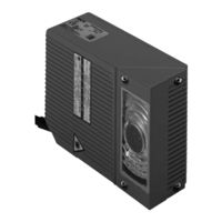
SICK ICR 84x Operating Instructions Manual (182 pages)
Scanner family for reading 1-D and 2-D codes
Brand:
SICK
| Category:
Barcode Reader
| Size: 3 MB
Table of Contents
Software Versions
2
Table of Contents
5
1 Notes on this Document
13
Purpose
13
Target Audience
13
Installation, Electrical Installation, Maintenance and Replacement
13
Startup, Operation and Configuration
13
Information Content
13
Symbols
14
2 Safety Information
15
Authorized Users
15
Installation and Maintenance
15
Electrical Installation and Replacement
15
Startup, Operation and Configuration
15
Intended Use
15
General Safety Precautions and Protection Measures
16
RF Interferences
16
Electrical Installation
16
LED Illumination for Reading Area
16
Quick Stop and Quick Restart
17
Switching the ICR off
17
Switching the ICR on Again
17
Fig. 2-1: Black-Yellow Signed Warning Labels Found on the ICR
17
Environmental Information
18
Power Requirements
18
Disposal after Final Removal from Service
18
3 Product Description
19
Design
19
Scope of Delivery
19
Variants
19
Table 3-1: ICR 84X Variants
19
System Requirements
20
Product Features and Functions (Overview)
21
View of the Device
23
Fig. 3-1: Design of the ICR
23
Method of Operation
24
Fig. 3-2: Reading Area of the ICR in the Focus Position (Standard Type)
24
Fig. 3-3: Block Diagram: Functions of the ICR
24
Indicators and Control Elements
26
Control Elements
26
Function of the Leds
26
Fig. 3-4: Leds
26
Table 3-2: Meaning of the General Leds
27
Table 3-3: Meaning of the Leds of the Ethernet Interface
27
Function of the Beeper
28
Table 3-4: Beeper Function
28
4 Installation
29
Overview of Installation Sequence
29
Installation Preparations
29
Laying out the Components to be Installed
29
Laying out Accessories
29
Laying out the Required Tools
29
Selecting the Installation Site
30
Mounting Accessories
31
Fig. 4-1: Position of the Securing Threads on the ICR
31
Distance between ICR and Code
32
Fig. 4-3: Alignment of the ICR Reading Area with the Code
32
Fig. 4-4: Definition of the Reading Distance
32
Table 4-1: Permissible Reading Angle between the Reading Area and the Bar Code/2-D Code When Reading with Omni-Directional Decoder
33
Table 4-2: Permissible Reading Angles between the Reading Area and Bar Code When Reading with Standard/Smart Decoder
33
Count Direction of the Code Position CP
34
Fig. 4-6: Installing the ICR Parallel to the Object Surface
34
Fig. 4-7: Count Direction of the Code Position CP for Bar Codes Along the Reading Window
34
Installing and Adjusting the Device
36
Installing the ICR
36
Installing External Components
37
Installing the CDB 420 or CDM 420 Connection Module
37
Installing the External Reading Pulse Sensor
37
Fig. 4-8: Line Scanner: Installation Example for the External Reading Pulse Sensor
37
Installing the Incremental Encoder
38
Removing the Device
38
5 Electrical Installation
39
Overview of the Installation Sequence
39
SICK Connection Modules (Overview)
39
Electrical Connections and Cables
39
Tab. 5-1: Connection Modules for the ICR
39
Pre-Fabricated Cables (Overview)
40
Connections/Cables for the CDB 420 or CDM 420 Connection Module
40
Tab. 5-2: Cables for Connecting the ICR
40
Fig. 5-1: Block Diagram: Connection of the ICR to the CDB 420 or CDM 420 Connection Module
40
Pin Assignments
42
Cable Plug
42
RJ 45 Socket 10Baset (Ethernet)
42
Table 5-3: Pin Assignment of the 15-Pin D-Sub HD Plug
42
Table 5-4: Pin Assignment of the 8-Pin RJ 45 10Baset Socket
42
Electrical Installation Preparations
43
Requirements for the Host Interface
43
Power Supply
43
Table 5-5: Maximum Cable Lengths between the ICR and Host
43
Table 5-6: Power-Up Delay as a Function of the Device Number GN
43
Non-SICK Power Supply Unit/Connections Without the SICK Connection Module
44
Table 5-7: Wiring Color Assignment of Cable No. 6 010 137 (Open End)
44
Performing Electrical Installation
45
Overview of Connection Procedure
45
Tools
45
Connecting the Power Supply
45
Connecting the Host Interface
46
Table 5-8: Communication Parameters for the Host Interface (Default Setting)
46
Fig. 5-2: Connections of the Host Interface
46
Connecting the CAN Interface
47
Connecting the Ethernet Interface
48
Table 5-9: Ethernet Interface Communication Parameters (Default Setting)
48
Fig. 5-3: Block Diagram: Function of the Ethernet Interface
48
Connecting the PC
50
Table 5-10: Communication Parameters for the Auxiliary Interface
50
Fig. 5-4: Connection of the Auxiliary Interface
50
Connecting the "Sensor 1" Switching Input
51
Table 5-11: Characteristic Data of the "Sensor 1" Switching Input
51
Fig. 5-5: Connections of the "Sensor 1" Switching Input
51
Connecting the "Sensor 2" Switching Input
52
Fig. 5-6: Connections of the "Sensor 2" Switching Input
52
Connecting the "Result 1" and "Result 2" Switching Outputs
53
Table 5-12: Characteristic Data of the "Result 1" Switching Output
53
Fig. 5-7: Connection of the "Result 1" Switching Output
53
Table 5-13: Characteristic Data of the "Result 2" Switching Output
54
Fig. 5-8: Connection of the "Result 2" Switching Output
54
6 Operation
55
Overview of the Startup Procedure
55
Default Setting
55
Table 6-1: Extract: Default Setting of the ICR Parameter Values
56
Quick Start
57
Starting up the ICR for Test Reading with the Factory Default Setting
57
Fig. 6-1: 2-D Code Sample (Datamatrix ECC200; Cell Size 0.3 MM (11.8 Mil))
57
Fig. 6-2: Bar Code Sample (Code 39; Module Width 0.35 MM (13.8 Mil); Print Ratio 2:1)
57
Configuring the ICR for the Application with the Setup Assistant
58
Fig. 6-3: CLV Assistant: Starting up Window
59
Fig. 6-4: CLV Assistant: "Connection Assistant" Dialog Box
60
Fig. 6-5: CLV Assistant: "Ethernet Assistant" Dialog Box after an ICR Has Been Detected in the Network (Here: IP Address in the Default Setting of the ICR)
60
Fig. 6-6: CLV Assistant: "Ethernet Assistant" Dialog Box after a New IP Address/Mask Has Been Assigned to the ICR (Here: 010.224.055.084/255.255.248.000)
61
Fig. 6-7: CLV Assistant: Dialog Box Confirming that Communication with the ICR Via Ethernet (TCP/IP) Is Successful
62
Fig. 6-8: CLV Assistant: "Scanner Adjustment" Dialog Box
62
Fig. 6-9: Imageftp: "IP Address" Dialog Box
63
Fig. 6-10: Imageftp: Program Window
63
Fig. 6-11: Imageftp: Image Output When Adjusting the ICR (before Starting the Autosetup)
64
Fig. 6-12: Imageftp: "User Accounts" Dialog Box
64
Fig. 6-13: Imageftp: "Edit Directory" Dialog Box
65
Fig. 6-14: Imageftp: "Visualization" Dialog Box
66
Fig. 6-15: CLV Assistant: "Datamatrix Autosetup" Dialog Box (Part 1)
66
Fig. 6-16: CLV Assistant: "Datamatrix Autosetup" Dialog Box (Part 2)
67
Fig. 6-17: Imageftp: Image Output When Preparing the Autosetup
67
Fig. 6-18: CLV Assistant: "Datamatrix Autosetup" Dialog Box after Successful Reading
68
Fig. 6-19: CLV Assistant: Display of the Performed Steps and Determined Values
68
Fig. 6-20: CLV Setup: Status Line with IP Address/Port of the Ethernet Connection
69
Fig. 6-21: CLV Setup: "Interface Options" Dialog Box Line with IP Adress/Port of the Ethernet Connection
69
Fig. 6-22: Imageftp: Image Output, with the Markings for CP Limitations (Violet), the 2-D Symbol (Green) and the Position of the Datamatrix Decoder at the End of Reading Pulse (Blue)
70
Configuration (Parameterizing)
71
Configuring the ICR with the User Interface of CLV Setup
71
Function of Tabs in CLV Setup (Overview)
73
Parameterization Guide
75
Table 6-2: Guide: Parameterizing the Reading Trigger and Output of Reading Result
76
Table 6-3: Guide: Parameterizing the Illumination Timeout
79
Table 6-4: Guide: Settings to be Made for the Evaluation of Identical Codes
80
Operating Modes and Outputting the Reading Result
82
Reading Mode (Standard Operating Mode)
82
Fig. 6-23: CLV Setup: Output of the Reading Result of the Auxiliary Interface for 2-D Codes in the Terminal Emulator
84
Fig. 6-24: Position of the Symbol in the Image Field of the Image Memory
85
Fig. 6-25: CLV Setup: Output of the Reading Result of the Auxiliary Interface for Bar Codes in the Terminal Emulator
86
Percentage Evaluation
88
Fig. 6-26: CLV Setup: Display of the Percentage Evaluation of the Auxiliary Interface for Bar Codes in the Terminal Emulator
89
Image Acquisition
90
Table 6-5: Imageftp: Functions of the Icon Buttons
91
Fig. 6-27: Imageftp: Program Window
91
Table 6-6: Imageftp: Colors for Displaying the Reading Diagnosis Data
92
Fig. 6-28: Imageftp: Image Output, with the Marks for CP Limitations (Violet), the 2-D Symbol (Green) and the Position of the Datamatrix Decoder at the End of Reading Pulse (Blue)
92
Displaying and Editing Operating Data
93
Reading Diagnosis
93
Fig. 6-29: CLV Setup: "Operating Data" Dialog Box
93
Monitor Host Interface
94
Table 6-7: "Monitor Host Interface" Function
94
Fig. 6-30: CLV Setup: Output of the Reading Result of the Host Interface in the Terminal Emulator (in this Case: O = Output)
95
Auxiliary Input
96
Self-Test
96
Fig. 6-31: CLV Setup: Displaying the Self-Test Result in the Terminal Emulator
97
Performing Device Functions of ICR in the Dialog Box
98
Fig. 6-32: CLV Setup: Dialog Box for Executing Matchcode Teach-In
98
ICR Messages
99
Displaying Messages
99
Fig. 6-33: CLV Setup: Displaying the System Messages in the Terminal Emulator When Starting the ICR
99
Error Messages
100
Switching the ICR off
100
7 Maintenance
101
Cleaning During Operation
101
Fig. 7-1: Cleaning the Reading Window
101
Maintenance
102
Disposal
102
Fig. 7-2: Cleaning the External Optical Sensor (Reading Pulse Generator)
102
8 Troubleshooting
103
Overview of Errors and Malfunctions Which Could Occur
103
Installation Errors
103
Electrical Connection Errors
103
Parameterization Errors
103
Malfunctions During Operation
103
Monitoring Errors and Malfunctions
103
Error Messages
104
Table 8-1: Error Message Output to the Auxiliary Interface
104
ST Error Status in the Reading Result of a Bar Code
105
Table 8-2: Meaning of the ST Error Status in the Reading Result
105
Troubleshooting
106
General Malfunction: ICR Not Ready
107
Table 8-3: Troubleshooting: Restoring Operation (Reading Mode)
107
Malfunctions in Reading Mode: Reading Pulse Errors
108
Table 8-4: Troubleshooting: Reading Pulse Errors in Reading Mode
108
Malfunctions in Reading Mode: Result Output Errors
111
Table 8-5: Troubleshooting: Result Output Errors in Reading Mode (General Malfunctions)
111
Table 8-6: Troubleshooting: Result-Status Output Errors in Reading Mode (Reading 2-D Codes)
113
Table 8-7: Troubleshooting: Result-Status Output Errors in Reading Mode (Reading Bar Codes)
114
Malfunctions in Reading Mode: Errors When Outputting the Result Status
115
Table 8-8: Troubleshooting: Errors in the Result Status Output in Reading Mode
115
Malfunctions: Configuration Errors (Parameterization)
116
Table 8-9: Troubleshooting: Errors When Using the Setup Assistant
116
Malfunctions: Errors When Using the Image Outputting in Reading Mode
117
SICK Support
117
Table 8-10: Troubleshooting: Errors When Using the Image Transfer Via the Ethernet Interface
117
9 Technical Data
119
Data Sheet for ICR 84X Image Code Reader
119
Table 9-1: Technical Specifications of ICR 84X
119
Suitable Bar Code Lengths in the Reading Area
120
Table 9-2: Suitable Bar Code Lengths at Focus Position
120
ICR 84X Dimensional Drawing
121
Fig. 9-1: Dimensions of the ICR
121
Specification Diagram
122
Reading Conditions for the Diagrams
122
Reading Ranges of ICR - Preliminary
122
Table 9-3: Reading Conditions for Specification Diagrams
122
Fig. 9-2: ICR 840 (Standard Type): Reading Range and Length of the Reading Area
122
Reading Area Mapped in the Image Buffer Memory - Preliminary
123
Fig. 9-3: ICR 840 (Standard Type): Reading Range and Width of the Reading Area
123
Fig. 9-4: ICR 840 (Standard Type): Reading Area and Reading Range in Dependence of the Reading Distance
123
10 Appendix
125
Appendix Overview
125
System Messages
126
Table 10-1: System Messages of the ICR
126
Installation and Operating Instructions for the PC-Based "CLV Setup" Program
127
Preparing for Installation
127
Performing Installation
127
Starting "CLV Setup
130
Table 10-2: Default Settings in CLV Setup (Extract)
130
Fig. 10-1: CLV Setup: Results of the Autobaud Detect Function
131
CLV Setup User Interface
132
Fig. 10-2: User Interface of the "CLV Setup" Software
132
Functions
133
Hot Keys
133
Opening and Closing Tabs
134
Online Help Program "CLV Setup Help
134
Transferring Parameter Sets between CLV Setup and the ICR
135
10.3.10 Unknown Parameters
135
10.3.11 Logging File in Terminal Emulator
136
10.3.12 Starting CLV Setup with an INI File as an Argument
136
10.3.13 the CLV Assistant
136
Settings for Reading Datamatrix ECC 200
137
Improving the Image Quality
137
Fig. 10-3: CLV Setup: "Reading Configuration" Tab
138
Fig. 10-4: CLV Setup: "Code Configuration" Tab
138
Fig. 10-5: CLV Setup: "Datamatrix" Tab
139
Fig. 10-6: CLV Setup: "Code Properties Parameters" Tab
140
Fig. 10-7: CLV Setup: Using the "Deviation of Dot Size" Slider
141
Fig. 10-8: CLV Setup: "Optimisation" Tab
141
Fig. 10-9: CLV Setup: "Code Properties Parameters" Tab
143
Fig. 10-10: CLV Setup: "Reading Configuration" Tab
143
Optimizing Reading Characteristics for Special Applications
144
Fig. 10-11: CLV Setup: "Code Configuration" Tab
144
Fig. 10-12: CLV Setup: "Datamatrix" Tab
144
Fig. 10-13: CLV Setup: "Code Properties Parameters" Tab
145
Fig. 10-14: Limiting the Active Evaluation Area in the Image Memory
146
Fig. 10-15: CLV Setup: "Optimization" Tab
146
Fig. 10-16: CLV Setup: "Reading Configuration" Tab
147
Fig. 10-17: CLV Setup: "Code Properties Parameters" Tab
148
Configuring the ICR with Command Strings
149
Fig. 10-18: CLV Setup: Entering Commands in the Terminal Emulator
150
Auxiliary Tables
151
Calculating Code Length of a Bar Code
151
Table 10-3: Formulas for Calculating the Code Length of a Bar Code
151
Special Applications and Procedures
152
Triggering the Teach-In Match Code 1 Via the "Sensor 2" Switching Input
152
Auxiliary Input Via the Auxiliary Interface
158
Fig. 10-20: Auxiliary Input Via the Auxiliary Interface of the ICR
158
Table 10-4: Communication Parameter Settings for the Terminal/Pc for the Auxiliary Input
160
Fig. 10-21: CLV Setup: Auxiliary Input Via the Terminal Emulator
160
Connection to Profibus DP
161
Connection to Devicenet
161
Building up a CAN Scanner Network
161
Table 10-5: Communication Parameter Settings for the SICK Hand-Held Scanner from the IT 38Xx/46Xx/48Xx/58Xx Series
161
Replacing an ICR (Transferring the Parameter Set)
162
Transferring the Parameter Set Using a Download
162
Accessories
164
Installation Accessories
164
Connection Modules
164
Table 10-6: Accessories: Installation Accessories
164
Extensions for Connection Modules
165
Table 10-8: Accessories: Extensions for Connection Modules CDB 420/CDM 420
165
Cables and Plug-In Connections
166
Reading Pulse Generators
166
Incremental Encoder
166
Table 10-9: Accessories: Cables and Plug-In Connections
166
Table 10-10: Accessories: Incremental Encoder
166
10.10 Dimensional Drawings of the Accessories
167
Mounting Bracket (for an ICR)
167
10.11 Supplementary Documentation
168
CLV Connect (from Version > 2.0)
168
Table 10-11: Supplementary Documentation
168
10.12 Glossary
169
10.13 EC Declaration of Conformity
175
Fig. 10-23: Copy of the Declaration of Conformity (Page 1, Scaled Down)
175
10.14 Index
176
10.15 Code Samples
181
1-D and 2-D Code Samples for ICR 840 (Standard Type)
181
Fig. 10-24: Scannable 1-D Codes with Various Module Widths (Print Ratio 2:1)/2-D Code
181
Advertisement
Advertisement
Related Products
SICK ICR803
SICK ICR845-2
SICK ICD8 Series
SICK ICI890-23 Series
SICK ICI890-24 Series
SICK ICI890-25 Series
SICK ICI890-33 Series
SICK ICI890-34 Series
SICK ICI890-35 Series
SICK IDM260 Series
SICK Categories
Accessories
Security Sensors
Measuring Instruments
Scanner
Barcode Reader
More SICK Manuals
Login
Sign In
OR
Sign in with Facebook
Sign in with Google
Upload manual
Upload from disk
Upload from URL