Table of Contents
Advertisement
High Mount
High Mount
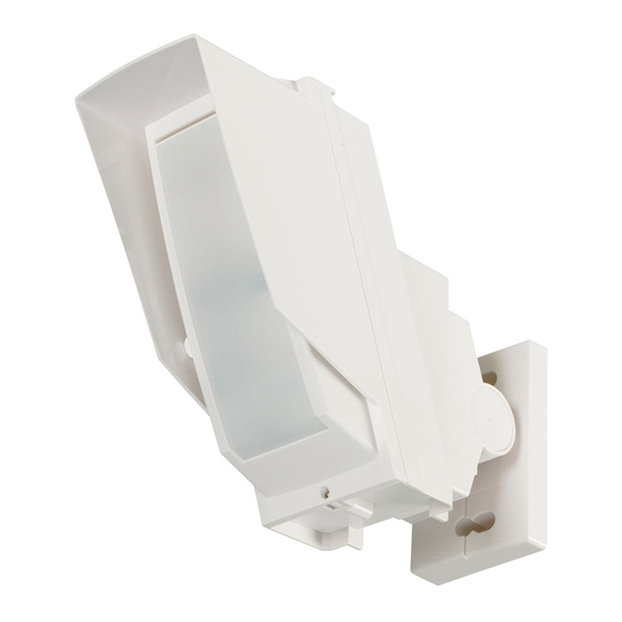
Outdoor Detector
Outdoor Detector
HX-80N/80NAM
HX-80N/80NAM
HX-80N
2 PIRs standard model
HX-80NAM HX-80N with anti-masking
•
Long distance detection area (24.0 m)
•
Flexible detection area setting with plates and flaps
•
Unique pyro element
•
Intelligent AND logic
•
Dual signal processing logic
•
Vegetation sway analysis logic
•
Digital anti-masking (AM model)
INSTALLATION INSTRUCTIONS
CONTENTS
1 INSTALLATION PRECAUTIONS ............2
1-1 BEFORE INSTALLATION ................2
1-2 PARTS IDENTIFICATION ................3
1-3 KNOCKOUTS ..................................3
2 DETECTION AREA.................................4
RANGE DETECTION AREA ............6
RANGE DETECTION AREA ............8
3 INSTALLATION .....................................10
3-1 INSTALLING WITH BRACKET ......10
ANGLE...........................................12
BRACKET ......................................12
3-4 WIRING .........................................13
3-5 WALL TAMPER (OPTION) ............14
4 WALK TEST ..........................................16
5 SETTING ..............................................16
6 LED INDICATION .................................18
7 SPECIFICATIONS ................................19
7-1 SPECIFICATIONS .........................19
7-2 DIMENSIONS ................................20
- 1 -
NO.59-1619-0
Advertisement
Table of Contents

Subscribe to Our Youtube Channel
Related Manuals for Optex HX-80N


Summary of Contents for Optex HX-80N
-
Page 1: Table Of Contents
HX-80N/80NAM HX-80N/80NAM CONTENTS 1 INSTALLATION PRECAUTIONS ....2 HX-80N 2 PIRs standard model 1-1 BEFORE INSTALLATION ....2 HX-80NAM HX-80N with anti-masking 1-2 PARTS IDENTIFICATION ....3 1-3 KNOCKOUTS ........3 • Long distance detection area (24.0 m) 2 DETECTION AREA.........4 • Flexible detection area setting with plates and flaps 2-1 OUTLINE OF DETECTION AREA ...4... -
Page 2: Installation Precautions
INSTALLATION PRECAUTIONS BEFORE INSTALLATION Failure to follow the instructions provided with this indication and improper Warning handling may cause death or serious injury. Failure to follow the instructions provided with this indication and improper Caution handling may cause injury and/or property damage. The check mark indicates recommendation. -
Page 3: Parts Identification
PARTS IDENTIFICATION Bracket base Base Terminals Main unit Cover PIR1 (Do not touch) Anti-masking infrared LED Bracket (HX-80NAM only) Shaft cover PIR2 (Do not touch) Lock Screw* (M4 × 35 mm) Screw (4 × 20 mm) Screw kit For joint For wall mounting Lens Screw (4 ×... -
Page 4: Detection Area
DETECTION AREA OUTLINE OF DETECTION AREA Plate 1 Upper flap Plate 2 Lower flap Flap fix position indicator Plate fix position indicator - 4 -... - Page 5 DETECTION AREA (factory default) - 5 -...
-
Page 6: How To Reduce The Long Range Detection Area
HOW TO REDUCE THE LONG RANGE DETECTION AREA To adjust the LONG range of detection, set the upper and lower flaps as follows: Upper flap Flap fix position indicator Lower flap Pull out the flap. Note>> If the lower flap is located at the factory default position, slide it out with your thumb. - Page 7 PIR long range detection area reduction The detection distance in the following table can be limited by combining the positions of the flap. Use the following table to determine the positions of the upper and lower flaps that set the required max.
-
Page 8: How To Deactivate The Short Range Detection Area
HOW TO DEACTIVATE THE SHORT RANGE DETECTION AREA To adjust the SHORT range of detection, set the upper and lower plates as follows: Plate 2 Plate 1 Plate fix position indicator * Plate 1 and 2 are identical. Remove the plate. Insert the plate into the position determined by the required masking distance until it clicks. - Page 9 PIR short range detection area deactivation Use the following table to determine the positions of the plates that set the required masked area. Lower Not used Upper Factory Not used N.A. default N.A. N.A. N.A. NOTE: Use only the following combinations for the plate settings. 24m(80') MASK Upper position: Factory default, Lower position: j...
-
Page 10: Installation
INSTALLATION Use the bracket for normal installation. The unit may be installed directly on the wall, without the bracket, only if the following three conditions are met; • The mounting height is less than 3m (9'10"). • Horizontal adjustment is not necessary. •... - Page 11 Determine the horizontal direction (left or Open the wiring knockout. right) of the detector before installing the bracket on the wall. To the right To the left Wiring knockout Open the Up-Down lock screw knockout Tighten screws 1 and 2, adjust the for connecting the bracket.
-
Page 12: Adjusting The Vertical Angle
ADJUSTING THE VERTICAL ANGLE For best performance, install detector parallel to the ground. Decide the detection length. To change the detection length, adjust the flap and plate positions. Refer to the 2-2, 2-3 for the details. 24.0 m (80') Perform walk test to ensure detector is parallel to the ground. -
Page 13: Wiring
Fasten the base to the wall. Install main unit after wiring to the terminal. WIRING Power wires should not exceed the following lengths. HX-80N HX-80NAM WIRE GAUGE 12 V 14 V 12 V 14 V 160 m 360 m 140 m 310 m AWG22 (0.33 mm... -
Page 14: Wall Tamper (Option)
WALL TAMPER (OPTION) Universal magnet switch may be mounted as a wall tamper. Installation space for magnet switch is provided on the back of the main unit and the bracket. Maximum size of an applicable magnet switch: D 9 mm (0.35") × W 40 mm (1.57") × H 9 mm (0.35") Magnet switch is not included. - Page 15 Install the other portion of the magnet switch to the back of the main unit or the bracket. Pull the wiring through the knockouts. When not using the bracket When using the bracket Tilt the bracket about 45° and pass through the wire. Wiring sponge pad Magnet switch...
-
Page 16: Walk Test
WALK TEST Set the DIP switch 1 (LED ON/OFF) to Check that the detector detects an “ON”. object in the intended detection area. The installation has been successful if the LED lights for two seconds after a person walks into the detection area. Detected Not detected Note>>... - Page 17 HX-80N -LED ON/OFF DIP switch HX-80NAM POSITION FUNCTION The LED lights when someone is detected. (Factory default) The LED does not light even if someone is detected. HX-80N -IMMUNITY DIP switch HX-80NAM POSITION FUNCTION IMMUNITY logic is not activated. (Factory default) IMMUNITY logic is activated.
-
Page 18: Led Indication
HX-80N -PIR SENSITIVITY HX-80NAM SENSITIVITY SELECTOR POSITION FUNCTION HIGH HIGH High sensitivity MIDDLE MIDDLE (Factory Middle sensitivity default) Low sensitivity HX-80N ANTI-MASKING -ANTI-MASKING SENSITIVITY HX-80NAM SENSITIVITY SELECTOR POSITION FUNCTION HIGH High sensitivity HIGH (Factory Normal sensitivity default) Disabled Caution>> After closing the cover, do not leave any objects closer than 1 meter from the unit. -
Page 19: Specifications
SPECIFICATIONS SPECIFICATIONS Model HX-80N HX-80NAM Detection method Passive infrared PIR Coverage 24.0 m × 2.0 m (80' × 6'7") narrow / 20 zones PIR distance limit 6.5 m, 10.0 m, 13.0 m, 18.0 m (22', 33', 42', 59') Detectable speed 0.3 m/s –... -
Page 20: Dimensions
205 (8.07) 93 (3.66) Unit: mm (inch) Unit: mm (inch) The HX-80N series is only a part of a complete system, therefore we cannot accept complete responsibility for any damages or other consequences resulting from an intrusion. - 20 -...
Need help?
Do you have a question about the HX-80N and is the answer not in the manual?
Questions and answers