Table of Contents
Advertisement
Advertisement
Table of Contents

Subscribe to Our Youtube Channel
Related Manuals for Matrix W1X ROWER


Summary of Contents for Matrix W1X ROWER
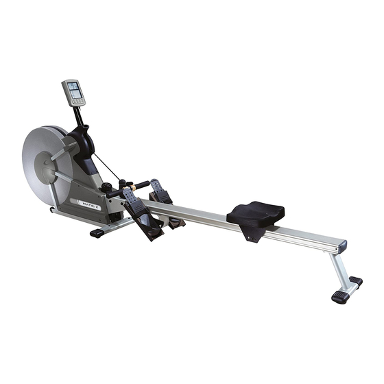
- Page 1 W 1 X R O W E R S E R V I C E M A N U A l...
-
Page 3: Table Of Contents
TAblE Of CONTENTS CHAPTER 1: SERIAl NUMbER lOCATION ......................CHAPTER 2: IMPORTANT SAfETy INSTRUCTIONS legal Disclaimer ..............................2 before Getting Started ..........................2 Read and Save These Instructions ......................3 CHAPTER 3: PREVENTATIVE MAINTENANCE Recommended Cleaning Tips ........................5 Check for Damaged Parts ..........................5 Care and Maintenance Instructions ...................... - Page 4 TAblE Of CONTENTS CHAPTER 7: ROWER SPECIfICATIONS AND ASSEMbly GUIDE Rower Specifications ............................35 Unpacking the Rower ............................. 36 fasteners and Assembly Tools ........................37 Assembly Instructions ........................... 38...
-
Page 5: Chapter 1: Serial Number Location
CHAPTER 1: SERIAl NUMbER lOCATION 1.1 SERIAl NUMbER lOCATION... -
Page 6: Chapter 2: Important Safety Instructions
Please do not place the Matrix W1x Rower in an area of high humidity, such as the vicinity of a steam room, indoor pool, or sauna. Exposure to intensive water vapor or chlorine could adversely affect the electronics, as well as other parts of the machine. -
Page 7: Read And Save These Instructions
To ensure safe use of the Matrix W1x Rower, make sure that all users read this manual. Remind the users that before undertaking any fitness CAUTION! Any changes of modifications to this equipment could void program, they should obtain complete physical examinations from the product warranty. -
Page 8: Chapter 3: Preventative Maintenance
3.2 CHECK fOR DAMAGED PARTS 3.1 RECOMMENDED ClEANING TIPS The Matrix W1x Rower is for use in the commercial environment. However, as DO NOT use any equipment that is damaged or has worn or broken a club owner or manager, you are responsible for cleaning and maintaining the parts. -
Page 9: Care And Maintenance Instructions
2) Check for dust inside of the flywheel with a flashlight and vacuum as you may periodically see addendums to this document, as the Matrix needed. Technical Support Team identifies items that require specific attention, the latest version will always be available on the Matrix web site at www. matrixfitness.com. -
Page 10: Workout Overview
CHAPTER 4: CONSOlE OVERlAy AND WORKOUT DESCRIPTION 4.1 WORKOUT OVERVIEW WORKOUT TIPS 1. Matrix fitness strongly recommends seeing your physician for a complete physical examination before beginning any fitness program. Know your physician's recommended heart rate target zone. If at any time while exercising, you experience faintness, dizziness, pain, or shortness of breath, you must stop immediately. -
Page 11: Workout Setup Steps
CHAPTER 4: CONSOlE OVERlAy AND WORKOUT DESCRIPTION 4.2 WORKOUT SETUP STEPS MANUAl PROGRAM TRAINING PROGRAM you can choose either Time or Distance as your target. Stroke Per Minute (SPM) training. you can either choose Time or Distance as your training target TIME: 1) Press the ON / Off button. -
Page 12: Chapter 5: Troubleshooting
CHAPTER 5: TROUblESHOOTING 5.1 TROUblESHOOTING - CONSOlE POWER ISSUES NO DISPlAy ON THE CONSOlE WHEN THE ON / Off bUTTON IS PRESSED POSSIblE CAUSES: 1) The console is damaged or the console cable is not connected properly. 2) The console batteries do not have enough power. SOlUTION 1) Check the console cable connection at the console. -
Page 13: Counting Issues
CHAPTER 5: TROUblESHOOTING 5.2 TROUblESHOOTING - COUNTING ISSUES COUNT VAlUE WON'T INCREASE WHIlE THE SEAT IS MOVING POSSIblE CAUSES: 1) Improper operation of the seat adjustment. 2) The console is damaged, or the console cable is not connected properly. 3) The stroke sensor has fallen out of the seat rail or is mispositioned. 4) The speed sensor is loosely attached or broken. -
Page 14: Rope Not Retracting
CHAPTER 5: TROUblESHOOTING 5.3 TROUblESHOOTING - ROPE NOT RETRACTING ROPE WIll NOT RETRACT OR RETRACTS SlOWly POSSIblE CAUSES 1) The spin axles are not wound tight enough. 2) The spin axles are defective. SOlUTION 1) Remove the middle shrouds as outlined in Section 6.2, and rewind the spin axles (figure A). The right side spin axle should be wound clockwise 2.5 - 3 revolutions, the left side spin axle should be wound counter clockwise 2.5 - 3 revolutions. -
Page 15: Chapter 6: Part Replacement Guide
CHAPTER 6: PART REPlACEMENT GUIDE 6.1 fRONT SHROUD REMOVAl 1) Remove the screw holding the shroud in place using a #2 Phillips Screwdriver. 2) figure b shows the rower with a front shroud removed. fIGURE A fIGURE b... -
Page 16: Middle Shroud Removal
CHAPTER 6: PART REPlACEMENT GUIDE 6.2 MIDDlE SHROUD REMOVAl 1) Remove the 4 screws holding the shroud to the frame (figure A). 2) figure b shows the rower with a middle shroud removed.. NOTE: When reinstalling the middle shroud, or when installing a new middle shroud, make sure the nut clips are positioned correctly (figure C). -
Page 17: Console Replacement
CHAPTER 6: PART REPlACEMENT GUIDE 6.3 CONSOlE REPlACEMENT 1) Disconnect the HR and RPM wires from the back of the console (figure A). 2) Remove the screw / nut holding the console to the console mast (figure b). 3) Remove the console (figure C). 4) Reverse Steps 1-3 to install a new console. -
Page 18: Handlebar Replacement
CHAPTER 6: PART REPlACEMENT GUIDE 6.4 HANDlEbAR REPlACEMENT 1) Pull the rope away from the console to create slack in the rope. 2) loosen the loops of the rope around the handlebar (figure A). 3) Remove the handlebar. 4) To install a new handlebar, create double loops in the rope and slide the new handlebar into place (figures b & C). fIGURE A fIGURE b fIGURE C... -
Page 19: Rubber Center Cover Replacement
CHAPTER 6: PART REPlACEMENT GUIDE 6.5 RUbbER CENTER COVER REPlACEMENT 1) Remove the console as outlined in Section 6.3. 2) Remove the handlebar from the rope as outlined in Section 6.4. 3) Remove the 3 screws holding the rubber center cover to the plastic (figure A). 4) lift up on the rubber center cover, and at the same time, pull the rope through the hole in the cover (figure b). -
Page 20: Plastic Center Cover Replacement
CHAPTER 6: PART REPlACEMENT GUIDE 6.6 PlASTIC CENTER COVER REPlACEMENT 1) Remove the console as outlined in Section 6.3. 2) Remove the handlebar from the rope as outlined in Section 6.4. 3) Remove the rubber center cover as outlined in Section 6.5. 4) Remove the 4 screws holding the plastic center cover to the frame (figure A). -
Page 21: Rope Replacement
CHAPTER 6: PART REPlACEMENT GUIDE 6.7 ROPE REPlACEMENT 1) Remove the right side middle shroud as outlined in Section 6.2. 2) Remove the console as outlined in Section 6.3. 3) Remove the handlebar from the rope as outlined in Section 6.4. 4) Remove the rubber center cover as outlined in Section 6.5. -
Page 22: Rope Pulley Replacement
CHAPTER 6: PART REPlACEMENT GUIDE 6.8 ROPE PUllEy REPlACEMENT 1) Remove the right side middle shroud as outlined in Section 6.2. 2) Remove the console as outlined in Section 6.3. 3) Remove the rubber center cover as outlined in Section 6.5. 4) Remove the plastic center cover as outlined in Section 6.6. -
Page 23: Spin Axle Replacement
CHAPTER 6: PART REPlACEMENT GUIDE 6.9 SPIN AXlE REPlACEMENT 1) Remove the middle shrouds as outlined in Section 6.2. 2) Remove the 3 screws holding the spin axle to the frame (figure A). 3) Remove the spin axle (figure b). 4) Reverse Steps 1-3 to install a new spin axle. -
Page 24: Rope Axle Replacement
CHAPTER 6: PART REPlACEMENT GUIDE 6.10 ROPE AXlE SET REPlACEMENT 1) Remove the front shrouds as outlined in Section 6.1. 2) Remove the middle shrouds as outlined in Section 6.2. 3) Remove the console as outlined in Section 6.3. 4) Remove the handlebar from the rope as outlined in Section 6.4. 5) Remove the rubber center cover as outlined in Section 6.5. - Page 25 CHAPTER 6: PART REPlACEMENT GUIDE 6.10 ROPE AXlE SET REPlACEMENT - CONTINUED fIGURE D fIGURE E fIGURE f fIGURE G...
-
Page 26: Magnet Set Replacement
CHAPTER 6: PART REPlACEMENT GUIDE 6.11 MAGNET SET REPlACEMENT 1) Remove the front shrouds as outlined in Section 6.1. 2) Remove the middle shrouds as outlined in Section 6.2. 3) Remove the console as outlined in Section 6.3. 4) Remove the handlebar from the rope as outlined in Section 6.4. 5) Remove the rubber center cover as outlined in Section 6.5. - Page 27 CHAPTER 6: PART REPlACEMENT GUIDE 6.11 MAGNET SET REPlACEMENT - CONTINUED fIGURE D fIGURE E fIGURE G fIGURE f fIGURE I fIGURE H...
-
Page 28: Speed Sensor Replacement
CHAPTER 6: PART REPlACEMENT GUIDE 6.12 SPEED SENSOR REPlACEMENT 1) Remove the right side front shroud as outlined in Section 6.1. 2) Remove the right side middle shroud as outlined in Section 6.2. 3) Remove the console as outlined in Section 6.3. 4) Remove the handlebar from the rope as outlined in Section 6.4. -
Page 29: Tension Set Replacement
CHAPTER 6: PART REPlACEMENT GUIDE 6.13 TENSION SET REPlACEMENT 1) Remove the front shrouds as outlined in Section 6.1. 2) Remove the middle shrouds as outlined in Section 6.2. 3) Remove the console as outlined in Section 6.3. 4) Remove the handlebar from the rope as outlined in Section 6.4. 5) Remove the rubber center cover as outlined in Section 6.5. - Page 30 CHAPTER 6: PART REPlACEMENT GUIDE 6.13 TENSION SET REPlACEMENT - CONTINUED fIGURE f fIGURE G fIGURE H fIGURE I fIGURE K fIGURE J...
-
Page 31: Center Axle Replacement
CHAPTER 6: PART REPlACEMENT GUIDE 6.14 CENTER AXlE REPlACEMENT 1) Remove the front shrouds as outlined in Section 6.1. 2) Remove the middle shrouds as outlined in Section 6.2. 3) Remove the console as outlined in Section 6.3. 4) Remove the handlebar from the rope as outlined in Section 6.4. 5) Remove the rubber center cover as outlined in Section 6.5. - Page 32 CHAPTER 6: PART REPlACEMENT GUIDE 6.14 CENTER AXlE REPlACEMENT - CONTINUED fIGURE D fIGURE E fIGURE f fIGURE G fIGURE H fIGURE I...
-
Page 33: Handlebar Bracket Replacement
CHAPTER 6: PART REPlACEMENT GUIDE 6.15 HANDlEbAR bRACKET REPlACEMENT 1) Remove the 2 screws holding the handlebar bracket to the frame (figure A). 2) Remove the handlebar bracket (figure b). 3) Reverse Steps 1-2 to install a new handlebar bracket. fIGURE A fIGURE b... -
Page 34: Console Cable Replacement
CHAPTER 6: PART REPlACEMENT GUIDE 6.16 CONSOlE CAblE REPlACEMENT 1) Remove the middle shrouds as outlined in Section 6.2. 2) Remove the console as outlined in Section 6.3. 3) Remove the handlebar from the rope as outlined in Section 6.4. 4) Remove the rubber center cover as outlined in Section 6.5. -
Page 35: Stroke Sensor Replacement
CHAPTER 6: PART REPlACEMENT GUIDE 6.17 STROKE SENSOR REPlACEMENT 1) Remove the handlebar bracket as outlined in Section 6.15. 2) Remove the 2 long screws / nuts holding the seat rail to the frame (figures A & b). 3) Disconnect the console cable from the stroke sensor wire (figure C). 4) Cut the tie strap holding the stroke sensor wire to the seat rail (figure D). -
Page 36: Seat Pad Replacement
CHAPTER 6: PART REPlACEMENT GUIDE 6.18 SEAT PAD REPlACEMENT 1) Remove the long screw / nut holding the bottom seat roller to the seat bracket set (figure A). 2) Remove the seat roller (figure b). 3) Remove the seat bracket set from the seat rail (figure C). 4) Remove the 4 screws holding the seat pad to the seat bracket set (figure D) and remove the seat pad. -
Page 37: Testing The Rower
CHAPTER 6: PART REPlACEMENT GUIDE 6.19 TESTING THE ROWER ONCE THE UNIT OR REPlACEMENT PART IS fUlly INSTAllED AND ASSEMblED AND PROPERly PlACED ON THE flOOR, USE THE fOllOWING INSTRUCTIONS TO TEST THE MACHINE: 1) Without hitting start or entering any program modes, sit on the machine and hold the handlebar while initiating movement to simulate exercising. While moving, listen for any odd noises or squeaks. -
Page 38: Chapter 7: Rower Specifications And Assembly Guide
CHAPTER 7: ROWER SPECIfICATIONS AND ASSEMbly GUIDE 7.1 ROWER SPECIfICATIONS CONSOlE Display Screen Extra large lCD display Display Readout Time, Distance, SPM (strokes per minute), Stroke, Watts, Heart Rate, Calories Programs Manual, Race, Training Telemetric HR Receiver Contact HR Sensors Transport Wheels TECHNICAl DATA Resistance Technology... -
Page 39: Unpacking The Rower
CHAPTER 7: ROWER SPECIfICATIONS AND ASSEMbly GUIDE 7.2 UNPACKING THE ROWER The Matrix W1x Rower is carefully inspected before shipment, so it should arrive in good operating condition. Matrix fitness ships the unit in the following pieces. NOTE : If these parts are missing from the package, please contact Matrix fitness at once. -
Page 40: Fasteners And Assembly Tools
CHAPTER 7: ROWER SPECIfICATIONS AND ASSEMbly GUIDE 7.3 fASTENERS AND ASSEMbly TOOlS... -
Page 41: Assembly Instructions
MAKING A CHOICE Of SITE The site should be well lit and well ventilated. locate the Matrix W1x Rower on a structurally solid and flat surface. If the site has a heavy plush carpet, to protect the carpeting and machinery, you should place a rigid plastic base under the unit. - Page 42 CHAPTER 7: ROWER SPECIfICATIONS AND ASSEMbly GUIDE 7.4 ASSEMbly INSTRUCTIONS STEP 1 1) Secure the front foot to the frame bracket using two bolts (H04).
- Page 43 CHAPTER 7: ROWER SPECIfICATIONS AND ASSEMbly GUIDE 7.4 ASSEMbly INSTRUCTIONS - CONTINUED STEP 2 1) Attach the pedal assembly to the aluminum rail with four bolts (H04) and spring washers (H05). 2) Attach the seat rail rod to the aluminum rail using one screw (f07) and flat washer (f19).
- Page 44 CHAPTER 7: ROWER SPECIfICATIONS AND ASSEMbly GUIDE 7.4 ASSEMbly INSTRUCTIONS - CONTINUED STEP 3 1) Mount the seat to the seat bracket with 4 screws (D09) and washers (D10). 2) Slide the seat assembly onto the aluminum rail. 3) Attach the seat stop bumper to the aluminum rail using the bolt (f07) and washers (f19).
- Page 45 CHAPTER 7: ROWER SPECIfICATIONS AND ASSEMbly GUIDE 7.4 ASSEMbly INSTRUCTIONS - CONTINUED STEP 4 1) Place the rear foot position plate (f04) inside the aluminum rail close to the edge. Attach the rear foot to the aluminum rail and align the four holes of the aluminum rail with the four holes of the rear foot.
- Page 46 CHAPTER 7: ROWER SPECIfICATIONS AND ASSEMbly GUIDE 7.4 ASSEMbly INSTRUCTIONS - CONTINUED STEP 5 1) Connect the sensor cable from the main frame and the aluminum rail. STEP 6 1) Place the aluminum rail into the rail bracket of the main frame, and tighten them using two bolts (f18), four washers (f06), and two nuts (f08).
- Page 47 CHAPTER 7: ROWER SPECIfICATIONS AND ASSEMbly GUIDE 7.4 ASSEMbly INSTRUCTIONS - CONTINUED STEP 7 Plug the two console cables into the console. Secure the console to the console support using the screw (N08) and nylon nut (N09).
- Page 48 NOTES...
- Page 49 M AT R I X f I T N E S S S y S T E M S CO R P. 16 10 l A N D M A R K D R I V E COT TA G E G R O V E W I 5 35 27 U S A w w w.
Need help?
Do you have a question about the W1X ROWER and is the answer not in the manual?
Questions and answers