Samsung DMT300 Series Service Manual
Hide thumbs
Also See for DMT300 Series:
- User manual (90 pages) ,
- Service training (53 pages) ,
- Training manual (52 pages)
Table of Contents
Advertisement
SERVICE
DISHWASHER
Refer to the service manual in the GSPN (see the rear cover) for more information.
DISHWASHER
Model Name :
DMT300 Series
Model Code :
DMT300RFS/XAA
DMT300RFB/XAA
DMT300RFW/XAC
MANUAL
1. Safety Instructions
2. Features and Specifications
3. Disassembly and Reassembly
4. Troubleshooting
5. PCB Diagram
6. Wiring Diagram
7. Schematic Diagram
8. Reference
DMT300RFS/XAC
DMT300RFB/XAC
DMT300RFW/XAC
Contents
Advertisement
Table of Contents

Related Manuals for Samsung DMT300 Series


Summary of Contents for Samsung DMT300 Series
- Page 1 DISHWASHER Model Name : DMT300 Series Model Code : DMT300RFS/XAA DMT300RFS/XAC DMT300RFB/XAA DMT300RFB/XAC DMT300RFW/XAC DMT300RFW/XAC SERVICE MANUAL DISHWASHER Contents 1. Safety Instructions 2. Features and Specifications 3. Disassembly and Reassembly 4. Troubleshooting 5. PCB Diagram 6. Wiring Diagram 7. Schematic Diagram 8.
-
Page 2: Table Of Contents
Wiring Diagram........................6 − 1 Schematic Diagram ........................... 7 − 1 7.1. Main Control .......................... 7 − 1 Reference ............................8 − 1 8.1. Model Number Naming Rules ....................8 − 1 8.2. Terminology ........................... 8 − 2 Copyright© 1995-2010 SAMSUNG. All rights reserved. -
Page 3: Safety Instructions
This may result in electric shock or fire, and may shorten the product lifetime. › • Do not place any containers with water on the dishwasher. › If the water is spilled, it may result in electric shock or fire. This will also shorten the product lifetime. Copyright© 1995-2010 SAMSUNG. All rights reserved. - Page 4 If you need to place the dishwasher on its back for servicing purposes, place a support(s) on the floor and lay it down carefully so the back is on the floor. Do not lay it down on its front or side. This may result in scratches to the surface or damage to the parts. › Copyright© 1995-2010 SAMSUNG. All rights reserved.
- Page 5 Check whether the product is level with the floor. Check if there are any deformations in the sink. Check that the dishwasher is firmly installed to the sink. › Vibrations can shorten the lifetime of the product. Copyright© 1995-2010 SAMSUNG. All rights reserved.
-
Page 6: Features And Specifications
Extremely quiet operation Efficient noise control technology is used for the quietest possible operation. Your new Samsung dishwasher will be quieter than ever. Self-cleaning filter Cleaning the filter yourself is a thing of the past! This product keeps food waste internally while operating, then drains it automatically with the water. -
Page 7: Specifications
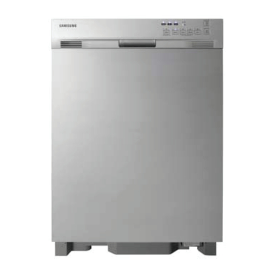
Standard amount of used water 3.9~7.9 gallon(14.7~30ℓ), Normal Cycle Size (W×D×H) 23 ⅞" x 24 ¾" x 33 ⅞" inch (605 x 627 x 860 mm ) NOTE Above images might differ in the dishwasher models. Copyright© 1995-2010 SAMSUNG. All rights reserved. -
Page 8: Comparing Specifications With Existing Models
Functional Specifications Soil Detection Sensors Drying method Air vent Air vent Air vent Condensing Condensing Condensing Basket Height Adjustment 2-stage 2-stage 2-stage 2-stage 2-stage 2-stage Half Load Child Lock Sanitize Leakage Sensor Delay start Copyright© 1995-2010 SAMSUNG. All rights reserved. -
Page 9: Options Specifications
(Bracket-install + Screw) Screw for side mounting Provided with the dishwasher User Manual Installation Guide DD68-00027A Elbow Water Supply Line (Flexible STS supply line is recommend) Air Gap Sold separately Rubber Connector Hose Clamp Strain Relief Copyright© 1995-2010 SAMSUNG. All rights reserved. -
Page 10: Disassembly And Reassembly
You must turn off the circuit breaker connected to the product. 4) Pull out the unit from the sink and lay it on the floor. Be careful of the drain hose when pulling out the unit. Copyright© 1995-2010 SAMSUNG. All rights reserved. -
Page 11: Standard Disassembly Drawings
4. Check the location of the thermistor and remove the two (2) screws that hold the thermistor to the case sump. 2. Remove the leakage sensor connector (white) inside the shutter. Copyright© 1995-2010 SAMSUNG. All rights reserved. -
Page 12: Heater
To remove a hook from the cover heater, insert the end of the screwdriver into the gap between cover heater and cover sump, and push the handle of screwdriver and the hook. Remove remain four(4) hooks using same way. Copyright© 1995-2010 SAMSUNG. All rights reserved. - Page 13 Make sure to check whether any water is left. the heater Remove any remaining water, to prevent water leakages while servicing. Do not pull the wire. Remove it by holding the metallic part at the end of the wire. Copyright© 1995-2010 SAMSUNG. All rights reserved.
-
Page 14: Drain Pump
4. Remove the drain pump by rotating it counterclockwise. shutter. When removing the drain pump, lift up the hook holding it in place slightly and then rotate it so that the hook is not damaged. Copyright© 1995-2010 SAMSUNG. All rights reserved. -
Page 15: Circulation Motor
Place the removed lower nozzle in a safe location along 4. Remove the sump assy. with the baskets. Remove the ten (10) screws on the assy filter mesh. (Except the two (2) screws holding the holder nozzle L in place) Copyright© 1995-2010 SAMSUNG. All rights reserved. - Page 16 Use your hand to hold the impeller damaged or hardened, replace it. circulation and turn the screw. CAUTION Turn the screw clockwise to remove it. 9. Remove the cutter disposer. CAUTION Both sides are sharp. Be careful when removing it. Copyright© 1995-2010 SAMSUNG. All rights reserved.
- Page 17 13. Remove the five (5) screws holding the circulation motor and the sump in place. 14. Hold and pull the circulation motor to remove it from the sump. 11. Remove the leakage sensor connector (white) inside the shutter. Copyright© 1995-2010 SAMSUNG. All rights reserved.
-
Page 18: Distributor Motor
Pull the distributor motor out. CAUTION 2. Remove the leakage sensor connector (white) inside Be careful removing because it is combine with the shutter. rubber seal and distributor valve. 3. Remove the two (2) distributor motor connectors. Copyright© 1995-2010 SAMSUNG. All rights reserved. -
Page 19: Leakage Sensor
CAUTION Do not place the removed screws on the tub front. They may fall into the sump assy. Copyright© 1995-2010 SAMSUNG. All rights reserved. 3-10... - Page 20 And, you can remove and replace the door lock switch in this step. (Remove both connectors of door lock switch.) 3-11 Copyright© 1995-2010 SAMSUNG. All rights reserved.
- Page 21 3. Disassembly and Reassembly 7. You can remove the PCB tact assy. Copyright© 1995-2010 SAMSUNG. All rights reserved. 3-12...
-
Page 22: Dispenser
The connectors are of the locking type and are hard to remove. Be careful not to break them when removing them. 4. Remove the six (6) screws holding the tub front and the two (2) bracket dispensers in place. 3-13 Copyright© 1995-2010 SAMSUNG. All rights reserved. -
Page 23: Fan Motor
2. Remove the fan motor & thermal actuator connectors. CAUTION Do not place the removed screws on the tub front. They may fall into the sump assy. 3. Remove the single (1) screw holding the bracket cover fan in place. Copyright© 1995-2010 SAMSUNG. All rights reserved. 3-14... - Page 24 Remove the screws first and carefully pull out the fan motor. 5. Remove the two (2) screws holding the cover fan in place. 8. Release the three (3) screws at side of case vent. 3-15 Copyright© 1995-2010 SAMSUNG. All rights reserved.
-
Page 25: Case Sensor
1. Remove the two (2) screws of the L frame. 2. Remove the L frame. CAUTION Make sure to wear gloves when removing the L frame. Be careful as the steel plate may harm you. Copyright© 1995-2010 SAMSUNG. All rights reserved. 3-16... -
Page 26: Inlet Valve & Flow Meter
Disconnect the micro switch connector. 3.2.11. Inlet Valve & Flow Meter 1. Place the dishwasher on its back and remove two (2) screws on both sides of the cover front lower. Remove the cover front lower. 3-17 Copyright© 1995-2010 SAMSUNG. All rights reserved. - Page 27 6. Pull out the inlet valve until the hose clamp can be removed, and remove the clamp and hose. CAUTION Take care when holding and removing the clamp with a tool, as it may bounce and harm you. Copyright© 1995-2010 SAMSUNG. All rights reserved. 3-18...
-
Page 28: Relay
2. When you separate the Frame R, you can check the screwdriver. Relay. CAUTION If reassemble the terminal of Relay after check or replacement, you must be careful. Don’t confuse. CAUTION Reassembly is in the reverse order of the removal. 3-19 Copyright© 1995-2010 SAMSUNG. All rights reserved. -
Page 29: Checkpoints After Finishing A Service
Check if there is any damage to the power cable or power outlet. Check that the power capacity is appropriate. 8) Check leveling Check whether the dishwasher is level. 9) Check the installation location Check whether the installation location is flat and stable. Copyright© 1995-2010 SAMSUNG. All rights reserved. 3-20... -
Page 30: Troubleshooting
When OFF status of Low Level S/W is not detected within 3 minutes Alien particles clogging mater drain hose. during the drain. Drain valve terminal not connected. Possible defect : Drain pump, Low Level Sensor, Main PBA. Copyright© 1995-2010 SAMSUNG. All rights reserved. - Page 31 When the button is pressed continuously for over 30 seconds. Possible defect : Sub PBA, Main PBA. Door open warnning When door is open in washing period. Door is not close properly. Possible defect : Door lock switch, Main PBA. Copyright© 1995-2010 SAMSUNG. All rights reserved.
-
Page 32: Service Inspection Mode
'Heavy' + 'Quick' LED Fan Motor The Fan Motor does not work. Operate Vent Motor and check whether Rinse aid is filled. Dispensor If there is not rinse in Dispenser, Rinse Refilled light is ON. Copyright© 1995-2010 SAMSUNG. All rights reserved. - Page 33 Remove the foreign material. Clean the filter with a brush. 3) Check whether any foreign material is in the Water Supply Line and • the Inlet Valve filter. • Reconnect the Inlet Valve connector. 4) Check the connection for the Inlet Valve connector. Copyright© 1995-2010 SAMSUNG. All rights reserved.
- Page 34 8) Check whether the water supply stops after water is supplied for 5 • Replace the Flow Meter. seconds. Check the water supply valve and increase the water pressure. 9) Check whether the water supply stops after water is supplied for 1 or • 5 minutes. Copyright© 1995-2010 SAMSUNG. All rights reserved.
- Page 35 CN101 connector and the amber wire of the CN201 connector. Remove Retainer. • • Normal: 120V (while operating) Check voltage • See the “Power Relay error”. 6) Check the operation of the Power Relay. • Copyright© 1995-2010 SAMSUNG. All rights reserved.
- Page 36 Heater Relay and the amber and yellow wires of the Power Relay, respectively. • Normal: Approx. 13Ω NOTE Check after disconnect circuit breaker or power cable. Copyright© 1995-2010 SAMSUNG. All rights reserved.
- Page 37 Faulty: Check the leakage location. Replace the faulty part. Leakage Error ‘Heavy’ LED Check whether there is any trace of water leakage in the shutter. • • Normal: No water leakage trace • Replace the Main PBA assy. Copyright© 1995-2010 SAMSUNG. All rights reserved.
- Page 38 5) Check whether an “Over Level Water Error” is detected when the assy • wire-harness connector for Overflow Sensor is not connected. • Nomral: Replace the Flow Meter. • Normal: The “Over Level Water Error” does not occur. Copyright© 1995-2010 SAMSUNG. All rights reserved.
- Page 39 Measure the resistance between both ends of the Thermistor: Remove the connector before measuring.(See the Table right.) THERMISTOR TABLE Temp. (ºC) Resistance (kΩ) 125.780 98.323 77.454 61.465 49.120 39.517 31.996 26.065 21.358 17.599 14.579 12.140 10.159 8.542 Copyright© 1995-2010 SAMSUNG. All rights reserved. 4-10...
- Page 40 Measure the voltage between the black wire and the white wire of CN101. • Nomral: AC 120V Check voltage. • • See “Main PBA DC voltage error”. 4) Check the DC voltage of the Main PBA. 4-11 Copyright© 1995-2010 SAMSUNG. All rights reserved.
- Page 41 9 (white) of the CN302 connector. • Normal (Power Key On): 9.5V to 12.5V • Check voltage (4.5V~5.5V) • Normal (Power Key Off): 5.5V to 7.0V • Check voltage (9.5V~12.5V or 5.5V~7.0V) Copyright© 1995-2010 SAMSUNG. All rights reserved. 4-12...
- Page 42 CN201 connector. • Remove Retainer. • Normal: 120V (while operating) Check voltage • Remove foreign material from the water passages. 5) Check whether there is foreign material in the water passages. • 4-13 Copyright© 1995-2010 SAMSUNG. All rights reserved.
- Page 43 1) Check the connections for the Door Sensing Switch : Check the blue wire and the switch connected to the blue wire. • Normal: 9.5 to 13.0V (when the door is open) • Normal: < 1V (when the door is closed) Copyright© 1995-2010 SAMSUNG. All rights reserved. 4-14...
- Page 44 7 (pink) of the CN302 connector. Normal: 4.5V to 5.5V • Measure the voltage between pin 6 (amber) of the main PBA CN302 • connector and pin 9 (white) of the CN302 connector. • Normal: 9.5V to 13.0V 4-15 Copyright© 1995-2010 SAMSUNG. All rights reserved.
- Page 45 : The Door Switch is ON. NOTE The Power Relay and the Heater Relay use a 12V line. If the switch is out of order, the Power Relay and the Heater Relay will not operate. Copyright© 1995-2010 SAMSUNG. All rights reserved. 4-16...
- Page 46 Heater Relay and the terminal (yellow wire+ amber wire) of the Power Relay CAUTION Check the color of the wires of the Power Relay and the Heater Relay. • Nomral: 120V 4-17 Copyright© 1995-2010 SAMSUNG. All rights reserved.
- Page 47 4) Check the operation of the Dispenser Relay. • Remove Retainer. Check the operating voltage between the white wire of the CN101 connector and the white wire of the CN201 connector. • Normal: 120V (while operating) Check voltage • Copyright© 1995-2010 SAMSUNG. All rights reserved. 4-18...
- Page 48 5) Check the operation of the Fan Motor Relay • • Remove Retainer. : Check the operating voltage between the white wire of the C101 • Normal: 120V (while operating) • Check voltage 4-19 Copyright© 1995-2010 SAMSUNG. All rights reserved.
- Page 49 2) Push ‘Normal’ Key 4 times 3) Push all key except Start/Pause Key. • Normal : All LED is light. See “Main PBA DC voltage error”. 3) Check the DC voltage of the Main PBA. • Copyright© 1995-2010 SAMSUNG. All rights reserved. 4-20...
-
Page 50: Pcb Diagram
Sensor, Turbidity Sensor, Rinse Aid Sensor Vent Motor Driving Relay Low Water Level Sensor, Overflow Sensor, Cold Water Counter, Electric Driving Connector Leakage Sensor, Temperature sensor, Door Sensor Micom Writer Connector Dispensor Driving Relay Drain Pump Driving Relay Copyright© 1995-2010 SAMSUNG. All rights reserved. -
Page 51: New Pba- Detailed Specifications And Descriptions For Connectors And Relay Terminals (Main Pba)
5. Circula tion P ump 6. NC 7. Cold Va lve CN701 (Micom Write r) 8. Dra in P ump 1. DC GND 2. MODE 9. NC 3. DC 5V 4. OCKIO 10. NC 5. OCDCK Copyright© 1995-2010 SAMSUNG. All rights reserved. -
Page 52: Wiring Diagram
6. Wiring Diagram 6. Wiring Diagram 6.1. Wiring Diagram Reference Information Abbreviated word Meaning GRAY ORANGE VIOLET PINK YELLOW BROWN WHITE BLACK SKY BLUE BLUE YELLOW/GREEN COLORLESS Copyright© 1995-2010 SAMSUNG. All rights reserved. -
Page 53: Schematic Diagram
7. Schematic Diagram 7. Schematic Diagram 7.1. Main Control NOTE This Document can not be used without Samsung’s authorization P OWER S UP P LY On boa rd DIS P LAY CONTROL writing R501 S 1-1 R502 AVDD S 2-1... -
Page 54: Reference
T : 24” Ta ll Tub 7,8 : Be s t 0 : Ba s ic H : Hidde n 5,6 : Be tte r 1 : Ve r. 1 F : Front 3,4 : Good Copyright© 1995-2010 SAMSUNG. All rights reserved. -
Page 55: Terminology
A passage that adjusts the air pressure by connecting the pressure of the inside air which is expanded at high temperature during the wash and rinse cycles and the outside air pressure. 15) Door Lock Switch Copyright© 1995-2010 SAMSUNG. All rights reserved. - Page 56 Detects whether the door of the dishwasher is open or closed. If the door is open while the dishwasher is running, the cycle is temporary stopped. 16) Child Lock › This function is used to prevent a child from operating the dishwasher while it is running. Copyright© 1995-2010 SAMSUNG. All rights reserved.
- Page 57 China http://china.samsungportal.com Asia http://asia.samsungportal.com Mideast & Africa http://mea.samsungportal.com This Service Manual is a property of Samsung Electronics © 2010 Samsung Electronics Co.,Ltd. Co.,Ltd. All rights reserved. Any unauthorized use of Manual can be punished under Printed in Korea applicable International and/or domestic law.
Need help?
Do you have a question about the DMT300 Series and is the answer not in the manual?
Questions and answers