Table of Contents
Advertisement
Quick Links
Advertisement
Table of Contents

Related Manuals for XtendLan DPM-IP700


Summary of Contents for XtendLan DPM-IP700
- Page 1 7-inch Digital Video Door Phone Quick Start Guide DPM-IP700...
- Page 2 Welcome Thank you for purchasing our product! This user’s manual is designed to be a reference tool for your system.
-
Page 3: Table Of Contents
Table of Contents Framework ........................... 1 Front Panel ........................1 Rear Panel ........................2 Basic Operations ........................3 Multiple-media Communication Function ..............3 2.1.1 Call ........................... 3 2.1.2 Monitor ........................5 2.1.3 Call History ......................5 2.1.4 Contacts ........................5 Information Search Function .................. - Page 4 Other functions......................15 2.10 Doorbell connection ....................16 Specifications ..........................17 FAQ ............................18...
-
Page 5: Framework
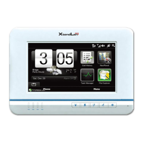
1 Framework 1.1 Front Panel Please connect the device to the power socket; you can see the power indication light is on. After system booted up, you can see the front panel is shown as below. See Figure 2-1. 1 2 3 12 1 Figure 1-1 Please refer to the following sheet for detailed information. -
Page 6: Rear Panel
The indication light is on (green) if the network Network indication light connection is OK. Power status indication The indication light is on (green) when the power light connection is OK. Shortcut menu Main menu button 1.2 Rear Panel The rear panel is shown as in Figure 1-2. Figure 1-2 Please refer to the following sheet for detailed information. -
Page 7: Basic Operations
2 Basic Operations 2.1 Multiple-media Communication Function button; you can go to the main interface. Click the “Call” In the standby mode, click the button; you can see there are five function buttons: call, monitor, leave messages, contacts. See Figure 2-1. Figure 2-1 2.1.1 Call 2.1.1.1 Call Household... - Page 8 2.1.1.2 Call Extension Number Click the “Call extension” button; you can talk to the extension number. The interface is similar to the Figure 2-2. 2.1.1.3 Call Management Centre Click the “Management centre” button; you can talk to the management centre. The interface is similar to the Figure 2-2.
-
Page 9: Monitor
2.1.2 Monitor In the main interface, select the multiple-media communication button and then select the “Monitor” button; you can view the video from the door station. See Figure 2-5. You can implement the following operations. Click the “Record” button; you can record the video from the monitor door station. The recorded files are saved in the monitor record. -
Page 10: Information Search Function
Figure 2-6 2.2 Information Search Function On the standby interface, click the button; you can go to the main interface. Click the”Information search” button; you can go to the information search interface. There are five buttons: information, video/audio record, monitor record, alarm log and visitors. All the information is listed by the time. -
Page 11: System Setup
Figure 2-9 2.3 System Setup On the standby interface, click the button; you can go to the main interface. Click the “Config” button. You can set the password, background, display, and ring, touch panel calibration, restore factory default setup, project installation and etc. You can set the corresponding parameters if necessary. -
Page 12: Background Setting
Figure 2-11 2.3.2 Background Setting In this interface, you can set the favorite background image. Click the Modify button, the modification is successfully saved. See Figure 2-12. Figure 2-12 2.3.3 Display Setting In the display interface, you can set brightness, contrast, hue, screen saver waiting time, screen saver last time. -
Page 13: Ring Setting
Figure 2-13 2.3.4 Ring Setting In the ring setup interface, you can set the incoming call ring, alarm ring , clock ring and set the ring volume. See Figure 2-14. Figure 2-14 2.3.5 Restore Default Setup The system supports restore default setup function. Go to the Restore default setup interface and then click the OK button. -
Page 14: Project Setting
Figure 2-15 2.3.6 Project Setting Please note this function is for system debug only. You need to contact our local project engineer for help. 2.4 Home Security button to go to the main interface. Click the “Home security” On the standby interface, click button, you can go to the home security interface. - Page 15 In the Indoor mode, select the area you want to set and then check the button to enable. See Figure 2-17. Please note you need to go to the following interface to set the area. Figure 2-17 Go to the system setting interface and then select the “Indoor mode”. Click the “Modify” button. See Figure 2-18.
-
Page 16: Home Appliances Control
Figure 2-19 2.4.2 Home Appliances Control Click the “Home appliances control” button; you can see the following interface. Here you can control the lights. See Figure 2-20. Figure 2-20 2.5 Tool button to go to the main interface. Click the “Tools” button; On the standby interface, click you can go to the tool interface. -
Page 17: Clock
Figure 2-21 2.5.1 Clock Time is synchronized from door station. Firstly pls set a proper time on your door station. Figure 2-22 2.5.2 Calculator In the “Tools” interface, click the “Calculator” button; you can go to the following interface. See Figure 2-23. -
Page 18: Unlock
2.6 Unlock 2.6.1 Unlock During the Dial Process During the dial process, you can open the e-lock of the door station remotely. There is a 15- second for you to confirm the unlock operation. During these 15 seconds, the video is properly displayed. -
Page 19: Dnd Function
2.7 DND Function This series product supports the do-not-disturb (DND) function. You can enable this function to shield the incoming ring. On the standby interface click the button, you can go to the DND setup interface. There are total six options: 0-hour/1-hour/2-hour/4-hour/8-hour/24-hour. You can enable or disable this function. -
Page 20: Doorbell Connection
2.10 Doorbell connection Pls connect a door bell to the first alarm port. After that set “Doorbell Ring” type according figure 2-27. Figure 2-277... -
Page 21: Specifications
3 Specifications Video Video compression H.264 standard Audio Bidirectional talk Dual-way bidirectional talk Screen Dimensions Color 7-inch TFT LCD Resolution 800*480 Alarm Cable, 8-channel Input Others Power DC 10~15V Power Standby<1W,work<5W consumption Working 0~50℃. Humidity: 20~80%RH environments (L*W*H) Dimensions 220mm*153mm*23mm Weight 500g... -
Page 22: Faq
4 FAQ Q: My indoor monitor screen is black and the indication light is off. What shall I do? A: Please check the power socket connection is OK or not. Q: My indoor monitor can not generate a call and implement the monitor function. The network indication light is off.
Need help?
Do you have a question about the DPM-IP700 and is the answer not in the manual?
Questions and answers