Table of Contents
Advertisement
Quick Links
Advertisement
Table of Contents

Related Manuals for XtendLan DPC-IP101ID


Summary of Contents for XtendLan DPC-IP101ID
- Page 1 DPC-IP101ID IP door station User manual...
-
Page 2: Table Of Contents
Table of Contents 1 Product Appearance 2 Basic Function Introduction 2.1 Call Manager Center 2.2 Call User 2.2.1 Connecting Status 2.2.2 Calling Status 2.3 Monitor 2.4 Web management 2.5 Single Call 2.6 Group Call 2.7 Unlock 2.7.1 Unlock under Connecting Status (access control module required) 2.7.2 Unlock under Calling Status (access control module required) 2.7.3 Unlock under Monitoring Status (access control module required) 2.7.4 Unlock via IC Card (access control module required) - Page 3 3.4 Status Statistics 3.4.1 VTH status 3.5 Logout 3.5.1 Reboot Device 3.5.2 Logout 4 Technical Specifications 5 Device Port Illustration 6. Installation Guide 7 FAQ...
-
Page 4: Product Appearance
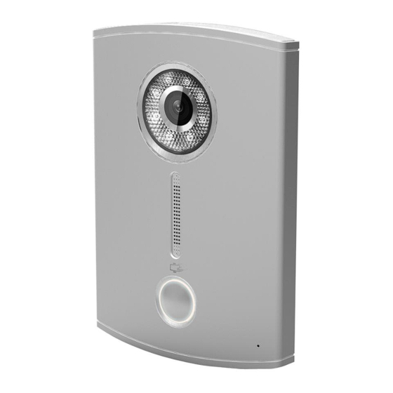
1 Product Appearance Please wait about 10s for the indicators in touch button to turn on after you plug the device to power supply. It takes about 60s for all the indicators to turn on and then off. After the system boots up properly, you will see its front as shown in Figure 1- 1(black) and Figure 1- 2 (white). - Page 5 Figure 1- 2 VTO is a signature for indoor monitors. VTH is a signature for outdoor stations VTS is a signature for a management center. For more than one monitor in the system please read the Group Call article about monitors compatible combinations.
-
Page 6: Basic Function Introduction
Name Function Light compensation will automatically Compensation turn on during connecting status if there is no enough light in environment. Camera It monitors corresponding door region. Card Swiping Area You can swipe card in this area. You can touch this button (the blue Touch Button indicator will be on) to call VTH or manager center. -
Page 7: Web Management
2.4 Web management The door station has a web management for user-friendly settings. To go to the web management open Internet Explorer web browser and go to 192.168.1.110 (default) IP address. Default login is admin/admin. 2.5 Single Call Go to the web management. Be sure Group Call is off. In the Indoor station manager input monitor data without IP address and reboot. -
Page 8: Group Call
Be sure DPC-IP102ID is added in the monitor settings well and is enabled there. 2.6 Group Call If you want to call via one button door station more than one monitor at the same time, you can use “group call” function. For group call you can´t connect every monitor models. This function you can use only for combination of DPM-IP70xTMD 2.6.1. - Page 9 2.6.2. DPC-IP102ID web management settings Input master monitor data WITHOUT IP address and reboot.
-
Page 10: Unlock
After rebooting open Indoor Station Manager again to upload slave monitors settings. 2.7 Unlock 2.7.1 Unlock under Connecting Status (access control module required) Under connecting status, VTS or VTH can remotely unlock door. VTO will return to standby interface after call ends or countdown stops. 2.7.2 Unlock under Calling Status (access control module required) Under calling status, VTS or VTH can remotely unlock door. -
Page 11: Unlock Under Monitoring Status (Access Control Module Required)
2.7.3 Unlock under Monitoring Status (access control module required) Under monitoring status, VTS or VTH can remotely unlock door. VTO will return to standby interface after call ends or countdown stops. 2.7.4 Unlock via IC Card (access control module required) By swiping authorized IC card, you can unlock door after local verification. -
Page 12: Deeper Introduction To Web
3 Deeper introduction to Web 3.1 Login Interface In Internet Explorer, input the IP address of VTO, a webpage pops up as in Figure 3- Figure 3- 1 Default username: admin Default password: admin. Click login to enter WEB interface. The WEB config interface consists of the following: Name Function... -
Page 13: Local Config
3.2.1 Local Config Local Config Local config includes issuing card, unlock and time setup. See Figure 3- 2. Figure 3- 2 Please note: 1) Frame rate: set 30 as frame rate for NTSC and 25 as frame rate for PAL standard. 2) Delete all: Click this button and then confirm. - Page 14 Figure 3- 3 Under local config interface, click on A&C manager. The initial VTO password is 123456 and to unlock, input #123456#. Here you can change password, set unlock responding interval and unlock period. FTP IP: FTP IP is used in storing snapshot taken by the VTO while user can view them by logging in this FTP IP.
-
Page 15: Indoor Station (Vth) Manager
System Time System time interface is shown in Figure 3- 4. Figure 3- 4 Under local config interface, click on system time where you can set time and sync it with PC. 3.2.2 Indoor Station (VTH) Manager Indoor station manager interface of VTO consists of add VTH, delete VTH and modify VTH user. -
Page 16: Lan Config
3.2.3 LAN Config LAN config interface is shown in Figure 3- 6. Figure 3- 6 Default config is OK if you merely want to ensure the LAN connection between VTO and VTH. If you want to config manager center, the config here must match info of the manager center, and you need to check box of register to the MGT center. -
Page 17: Change Password
3.2.5 Change Password Change password interface is shown in Figure 3- 8. Figure 3- 8 Here you can change the web login password of VTO. You need to input old password and new password and confirm new password. Click on OK to save. 3.3 Info Search 3.3.1 Call History Call history interface is shown in Figure 3- 9. -
Page 18: Status Statistics
3.4 Status Statistics 3.4.1 VTH status VTH status interface is shown in Figure 3- 10. Under status statistics interface, click on VTH status. Here you can view connection state of VTH. Figure 3- 10 3.5 Logout 3.5.1 Reboot Device Reboot device interface is shown in Figure 3- 11. Figure 3- 11 Here you can reboot the device. -
Page 19: Technical Specifications
Figure 3- 12 Here you can logout the device. 4 Technical Specifications Model DPC-IP102ID System Main processor Embedded microcontroller Embedded LINUX OS Video Video compression H.264 standard Input/Approaching 1.3 mega pixels CMOS HD camera Induction Night vision Support Audio Input Omnidirectional microphone Output Built-in loudspeaker... -
Page 20: Device Port Illustration
Power supply DC 10~15V Power Standby ≤1W ;working ≤10W consumption Environment -10℃~+60℃、10~95%RH Dimensions 115mm*45mm*155mm(L*W*H) Weight 0.5kg 5 Device Port Illustration Ports of VTO are illustrated in Figure 5- 1. Figure 5- 1 Port Name Description When this device is forced to leave wall, it will generate alarm Vandal proof switch sound and report to the... - Page 21 Description Port Name Network port Connect to RJ45 port. Power supply port Connect to 12V DC. Debug Port Green Port 1 Connect Lock Connect to magnetic feedback or Green Port 2 opening button A) Lock and Unlock Button. To connect Electric lock and unlock button to outdoor unit please see figure 6...
-
Page 22: Installation Guide
As shown in figure connect one terminal of Electric Lock with “NO” and next with “COM” on port 3 of outdoor unit. As shown in figure connect unlock button one terminal with “ALM1” and next terminal to “GND” on port 4 of outdoor unit. B) Door Sensor. - Page 23 Figure 6- 1 Installation step: Fix installation holder onto wall: Use the M4 screw accompanied with the VTO to fix holder onto the 86 box ○ in Figure 6- 1); In order to firm the VTO, use the ST4.0 screw accompanied with VTO to fix ○...
- Page 24 Installation step: Fix installation holder onto wall: Use the M4 screw accompanied with the VTO to fix holder onto the 86 box (as B is to strengthen firmness of VTO, use the ST3.0 screw accompanied with VTO to fix the 86 box onto wall after locking the 86 box. (as c) Install decoration cover (as 1) onto 2, secure with screw a.
-
Page 25: Faq
7 FAQ Q: How do I know if the power supply to VTO is working normally? A: After you plug the device to power supply, wait about 10s for the indicators in touch button to turn on. Approximately 60s later, all indicators will turn on as the device works normally.
Need help?
Do you have a question about the DPC-IP101ID and is the answer not in the manual?
Questions and answers