Table of Contents
Advertisement
Quick Links
Advertisement
Table of Contents

Related Manuals for XtendLan DPC-IP100


Summary of Contents for XtendLan DPC-IP100
- Page 1 Door Station User’s Manual DPC-IP100...
-
Page 2: Table Of Contents
Table of Contents Overview ........................1 Basic Functions ......................2 Call Residents ......................... 2 2.1.1 Call Status ......................2 2.1.2 Communication status ..................2 Monitor Function ......................2 Unlock Function ......................2 2.3.1 Unlock During the Dial Process................2 2.3.2 Unlock During the Communication .............. -
Page 3: Overview
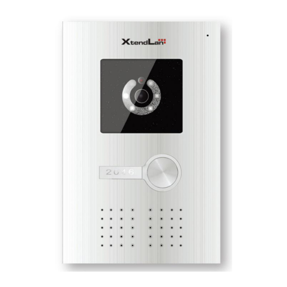
See Figure 1-1. Figure 1-1 Please refer to the following sheet for detailed information. Name Function Logo XtendLan LOGO Photosensitive It can detect the environment light. It is a Component compensation light option. It can compensate the camera light in Compensation Light the low illumination environments. -
Page 4: Basic Functions
backlight. Speaker Audio output Camera It is to monitor the video of the door. Microphone Audio input 2 Basic Functions 2.1 Call Residents 2.1.1 Call Status In the standby status, press the call button. You can generate a call to the resident indoor station. -
Page 5: Unlock During The Communication
2.3.2 Unlock During the Communication During the communication process, the indoor station can open the e-lock of the device remotely. There is a 15-second for you to confirm the unlock operation. During these 15 seconds, the communication is OK and the video is properly displayed. After the 15 seconds countdown, the phone automatically hangs up. -
Page 6: Changing Ip Address
3 Changing IP address 1..run ’ cmd’ 1).open 2.Input ‘telnet ’ device IP(e.g.10.22.5.182) Then press ’ Enter’ key 3.Username: root Press ‘Enter’ key Then input ifconfig... - Page 7 4. If want change the IP to 10.22.2.188 Can input: setenv –I ipaddr –c 10.22.2.188 5. The last step: Input ‘reboot’ or device is rebooted itself automatically.
-
Page 8: Config The 'Group Call Funtion
4 Config the ‘group call funtion’ 1. cmd:telnet outdoor station IP 2000 username :admin Password:admin... - Page 9 2、LAN Config: Group Call :Enable (After choose ‘Enable’, restore the station )
- Page 10 After config, please click the ‘Save’...
- Page 11 Add the room number: Choose the ‘VTH Manage’,click the ‘Enter’ Get this interface:...
- Page 12 Then can config the room number here. After add the new monitor, press the ‘Esc’ on the keyboard,choose the ‘save’...
-
Page 13: Specifications
5 Specifications Model DPC-IP100 Main Processor Embedded micro processor Embedded LINUX OS Video Video Compression H.264 Standard Input/Approaching 1/3-inch color CCD camera,540 TVL,0.1lux/F1.2 induction Night Vision Support Audio Input Microphone Output Built-in speaker Bidirectional Talk Support dual-way bidirectional talk Operation Mode... -
Page 15: Device Port
6 Device Port The device rear panel is shown as in Figure 6-1. Figure 6-1 Please refer to the following sheet for detailed information. Port Name Function Connect to alarm signal. Alarm port Network Port Connect to the RJ45 port. Power Port Connect to 12V DC. - Page 16 Door Lock Control Door phone is designed to be able to control the door lock. Figure 1 is its rear panel diagram. Figure 1 The interface “12DC” is for the power supply interface; “RJ45” for network cable; “door lock interface area” for electric lock. This user’s manual is based on electric lock. Figure 2 is the outward appearance of the electric lock.
- Page 17 Figure 2 Figure-3 is the connection diagram of the connection between door phone and electric lock. Figure 3 It is a transformer power supply, 220V AC is to be connected to L and N respectively to transform and then output 12 DC in order to supply power for the door phone and electric lock.
-
Page 18: Faq
7 FAQ Q:I can not boot up the device, or I can not see the light or hear the audio. A: Please check your power cable connection and socket connection. Q: I can not call. A: Please check your network connection. Please make sure your station and extension cable connection is OK. - Page 19 Note: This manual is for reference only. Slight difference may be found in user interface. All the designs and software here are subject to change without prior written notice. If there is any uncertainty or controversy, please refer to the final explanation of ...
Need help?
Do you have a question about the DPC-IP100 and is the answer not in the manual?
Questions and answers