
Related Manuals for TDK-Lambda Genesys GEN8-300


Summary of Contents for TDK-Lambda Genesys GEN8-300
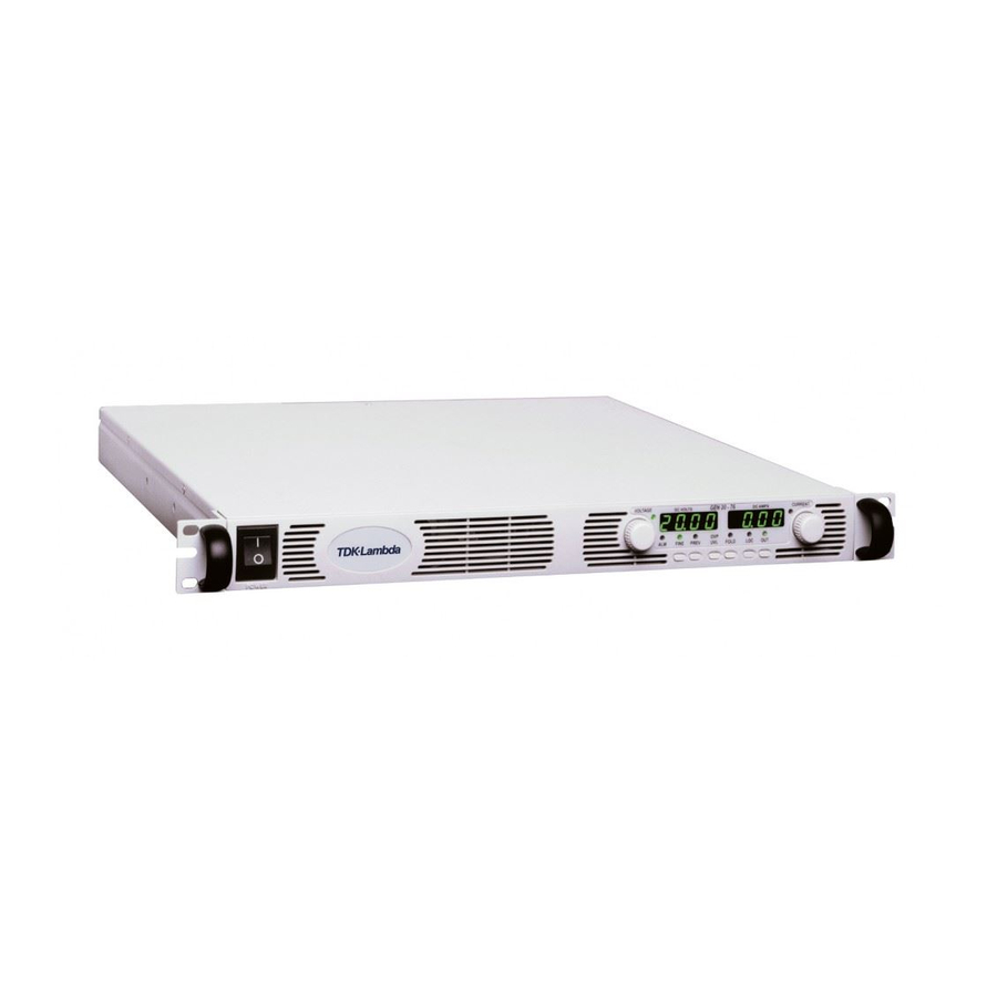
- Page 1 Programmable DC Power Supplies 2.4kW in 1U Built in RS-232 & RS-485 Interface Advanced Parallel Operation Optional Interface: Compliant LAN IEEE488.2 SCPI (GPIB) Multi-Drop Isolated Analog Programming User Manual...
- Page 2 SUPPLIES USER MANUAL GENESYS GEN 2.4kW SERIES POWER SUPPLIES USER MANUAL This Manual Covers Models: GEN8-300 GEN100-24 GEN30-80 GEN10-240 GEN150-16 GEN40-60 GEN16-150 GEN300-8 GEN60-40 GEN20-120 GEN600-4 GEN80-30 This Manual Covers Models: IA669-04-01 Rev.D GEN8-300 GEN100-24 GEN30-80 GEN10-240 GEN150-16 GEN40-60 GEN16-150 GEN300-8 GEN60-40 Manual Supplement...
-
Page 4: Gen20
DECLARATION OF CONFORMITY GEN2400W series We, TDK-Lambda Ltd., located at Haharoshet St. 56 Industrial Zone P.O.B. 500 Karmiel, Israel declare under our sole responsibility that the GEN2400W series as detailed on the products covered sheet comply with the provisions of... -
Page 5: Gen8
This page intentionaly left blank... -
Page 6: Table Of Contents
TABLE OF CONTENTS WARRANTY ............................Pg.1 REGULATORY NOTICES ........................Pg.2 SAFETY INSTRUCTIONS........................Pg.3 GERMAN SAFETY INSTRUCTIONS ....................Pg.5 ..................CHAPTER 1 GENERAL INFORMATION Pg.7 1.1 OPERATION MANUAL CONTENT ....................Pg.7 1.2 INTRODUCTION ..........................Pg.7 1.2.1 General description ........................ Pg.7 1.2.2 Models covered ........................Pg.7 1.2.3 Features and options ...................... - Page 7 TABLE OF CONTENTS 3.9 CONNECTING THE LOAD ......................Pg.19 3.9.1 Load Wiring .......................... Pg.19 3.9.2 Current Carrying Capacity ....................Pg.19 3.9.3 Wire termination ......................... Pg.20 3.9.4 Noise and Impedance Effects ....................Pg.21 3.9.5 Inductive loads ........................Pg.21 3.9.6 Making the load connections ....................Pg.21 3.9.7 Connecting single loads, local sensing (default) ..............
-
Page 8: Introduction
TABLE OF CONTENTS ..............CHAPTER 6 REMOTE ANALOG PROGRAMMING Pg.45 6.1 INTRODUCTION ........................... Pg.45 6.2 LOCAL/REMOTE ANALOG CONTROLL..................Pg.45 6.3 LOCAL/REMOTE ANALOG INDICATION..................Pg.45 6.4 REMOTE VOLTAGE PROGRAMMING OF OUTPUT VOLTAGE AND CURRENT LIMIT ..... Pg.46 6.5 RESISTIVE PROGRAMMING OF OUTPUT VOLTAGE AND CURRENT LIMIT ......Pg.47 6.6 REMOTE MONITORING OF OUTPUT VOLTAGE AND CURRENT .......... - Page 9 This page intentionaly left blank...
- Page 10 QA seal has been removed or altered by anyone other than TDK-Lambda Ltd. authorized personnel. TDK-Lambda Ltd. does not warrant the buyers circuitry or malfunctions of TDK-Lambda Ltd.
-
Page 11: Regulatory Notices
Safety - Part 1: General requirements. A “Declaration of Conformity” in accordance with the preceding directives and standards has been made and is on file at our EU representative TDK-Lambda Limited, located at Kingsley Avenue, Ilfracombe, Devon EX34 8ES, UK. -
Page 12: Safety Instructions
LIVE CIRCUITS Operating personnel must not remove the instrument cover. No internal adjustment or component replacement is allowed by non-TDK-Lambda Ltd. qualified personnel. Never replace components with power cable connected. To avoid injuries, always disconnect power, discharge circuits and remove external voltage source before touching components. - Page 13 SAFETY INSTRUCTIONS. ENVIRONMENTAL CONDITIONS The Genesys power supply series safety approval applies to the following operating conditions: *Indoor use *Ambient temperature: 0 C to 50 C *Maximum relative humidity: 90% (no condensation) *Altitude: up to 3000m *Pollution degree 2 Do not use this product in environments with strong Electromagnetic field, corrosive CAUTION gas and conductive materials.
-
Page 16: General Description
CHAPTER 1 GENERAL INFORMATION 1.1 USER MANUAL CONTENT This user’s manual contains the operating instructions, installation instructions and specifications of the Genesys 2400W power supply series. The instructions refer to the standard power supplies, including the built-in RS232/485 serial communication. For information related to operation with the optional LAN/IEEE programming, refer to User Manual for Power Supply LAN/IEEE Programming Interface. -
Page 17: Multiple Output Power System
* Parallel operation (Master/Slave) with Active current sharing. * Remote sensing to compensate for voltage drop of power leads. * External Analog Programming and Monitoring standard (0-5V or 0-10V, user selectable). * Cooling fan speed control for low noise and extended fan life. * Zero stacking- no ventillation holes at the top and bottom surface of the power supply. -
Page 18: Cooling And Mechanical Construction
1.2.9 Cooling and mechanical construction The Genesys series is cooled by internal fans. At the installation, care must be taken to allow free air flow into the power supply via the front panel and out of the power supply via the rear panel. -
Page 19: Chapter 2 Specifications
CHAPTER 2 SPECIFICATIONS 2.1 OUTPUT RATING MODEL 8-300 10-240 16-150 20-120 30-80 40-60 60-40 80-30 100-24 150-16 300-8 600-4 1.Rated output voltage(1*) 2.Rated output current (*2) 3.Rated output power 2400 2400 2400 2400 2400 2400 2400 2400 2400 2400 2400 2400 2.2 AUXILIARY OUTPUTS 1. -
Page 20: Programming And Readback
2.6.1 PROGRAMMING AND READBACK (RS232/485, Optional LAN/IEEE Interface) 1.Vout programming accuracy (*15) 0.05% of rated output voltage 2.Iout programming accuracy (*13) 0.1% of actual output current +0.2% of rated output current 3.Vout programming resolution 0.002% of rated output voltage 4.Iout programming resolution 0.002% of rated output current 5.Vout readback accuracy 0.05% of rated output voltage... -
Page 21: Safety/Emc
2.11 SAFETY/EMC Safety UL 60950-1, CSA22.2 No.60950-1, IEC 60950-1, EN 60950-1 EN55022, EN55024, EN61000-3-3, FCC part 15, VCCI. 1.Applicable standards: Conducted emmision - EN55022 class A, FCC part 15 class A, VCCI class A. Radiated emmision - EN55022 class A, FCC part 15 class A, VCCI class A. Immunity - EN55024 Models with Vout 50V: Output is SELV, all communication/control interfaces: RS232/485, IEEE, £... -
Page 22: Outline Drawings
2.13 GENESYS 2400W POWER SUPPLIES OUTLINE DRAWINGS GEN8-300 0-8V 0-300A T D L amb da 482.8+/-1.0mm 422.8+/-1.0mm Note 4 Note 1 Note 2 (150V~600V) Note 1 603.0+/-1.0mm Note 3 57.8+/-0.5 92.0+/-0.5 92.0+/-0.5 440.8+/-1.0mm Note 2 Bus-Bar Detail 8V to 100V Models NOTES: 1.Mating plug supplied with power supply. -
Page 23: Chapter 3 Installation
CHAPTER 3 INSTALLATION 3.1 GENERAL This chapter contains instructions for initial inspection, preparation for use and repackaging for shipment. Connection to PC, setting the communication port and linking Genesys power supplies are described in Chapter 7. WARNUNG WARNING The Genesys series is intended only for installation in Die Genesys ist ausschlie lich f r die Installation in ß... -
Page 25: Ac Input Connector
WARNING WARNUNG Some components inside the power supply are at AC Einige Komponenten innerhalb des Netzteils f hren ü voltage even when the On/Off switch is in the “Off ” Netzspannung, selbst wenn der On/Off-Schalter in der position. To avoid electric shock hazard, disconnect the Position “Off”... -
Page 26: Turn-On Checkout Procedure
4.Route the AC wires to the input connector terminals as required. To connect the wires, loosen the terminal screw, insert the stripped wire into the terminal and tighten the screw securely (4.4-5.3 Lb-inch.). 5.Route the wires inside the cover to prevent pinching. Fasten the cover to the unit using the M3x8 Flat Head screws are provided. -
Page 27: Constant Voltage Check
2. Connect the unit to an AC source as described in section 3.7. 3. Connect a DVM with appropriate cables for the rated voltage to the output terminals. 4. Turn the front panel AC power switch to On. 3.8.3 Constant Voltage Check 1. -
Page 28: Foldback Check
3.8.7 Foldback Check WARNING WARNUNG ß Das Kurzschlie en des Ausgangs kann den Anwender Shorting the output may expose the user to hazardous ä voltages. Observe proper safety procedures. einer gef hrlichen Spannung aussetzen. Beachten Sie die entsprechenden Sicherheitsrichtlinien. Refer to Section 5.5 for explanation of the FOLD function prior to performing the procedure below. -
Page 29: Wire Termination
2. Wire size should be selected to enable voltage drop per lead to be less than 1.0V at the rated current. Although units will compensate for up to 5V in each load wire, it is recommended to minimize the voltage drop (1V typical maximum) to prevent excessive output power consum- ption from the power supply and poor dynamic response to load changes. -
Page 30: Noise And Impedance Effects
3.9.4 Noise and Impedance Effects To minimize the noise pickup or radiation, the load wires and remote sense wires should be twisted- pairs to the shortest possible length. Shielding of sense leads may be necessary in high noise environments. Where shielding is used, connect the shield to the chassis via a rear panel Ground screw. - Page 32 The 150V to 600V models have a four terminal wire clamp output connector: Phoenix Contact P/N: FRONT4-H-7.62/4. The two left terminals are the positive outputs and the other two right terminals are the negative outputs. Max. 30A per terminal. The connector requirements are as follows: 1.
-
Page 33: Connecting Single Loads, Local Sensing (Default)
3.9.7 Connecting single loads, local sensing (default). Fig.3-11 shows recommended load and sensing connections for a single load. The local sense lines shown are default connections at the rear panel J2 sense connector. Local sensing is suitable for applications where load regulation is less critical. Load Power Supply... -
Page 34: Multiple Loads Connection With Distribution Terminals
Load lines, twisted pair, shortest length possible. Load#1 Power Supply Load#2 Rem.sense Local sense Load#3 Local sense Rem.sense Fig.3-13: Multiple loads connection, radial distribution, local sense 3.9.10 Multiple load connection with distribution terminals If remotely located output distribution terminals are used, the power supply output terminals should be connected to the distribution terminals by a pair of twisted and/or shielded wires. -
Page 35: Local And Remote Sensing
WARNING WARNUNG ERDUNG DER AUSGANGSKLEMMEN OUTPUT TERMINAL GROUNDING An RS232/485- und IEEE-Schnittstellen besteht die There is a potential shock hazard at the RS232/485 Gefahr eines elektrischen Schlags, wenn Netzteile and the IEEE ports when using power supplies with mit Nennausgangsspannung oder einer in Reihe rated or combined voltage greater than 400V with verschalteten Spannung von mehr als 400V mit the Positive Output of the power supplies is... -
Page 36: Remote Sensing
3.10.3 Remote sensing WARNING WARNUNG An den Anschlüssen für die Sense-Leitungen besteht There is a potential shock hazard at the sense point bei Stromversorgungen mit einer when using power supply with a rated output voltage Nennausgangsspannung von mehr als 40 V die greater than 40V. -
Page 37: Introduction
CHAPTER 4 FRONT AND REAR PANEL CONTROLS AND CONNECTORS 4.1 INTRODUCTION The Genesys Power Supply series has a full set of controls, indicators and connectors that allow the user to easily setup and operate the unit. Before starting to operate the unit, please read the following sections for explanation of the functions of the controls and connectors terminals. - Page 38 Table 4-1: Front Panel controls and indicators Number Control/Indicator Description Section 4 digit, 7-segment LED display. Normally displays the output current. When the PREV button is pressed, the CURRENT display display indicates the programmed setting of output current. CURRENT indicator Green LED, lights for Constant-Current mode operation. High resolution rotary encoder for adjusting the Output 5.2.2 CURRENT control...
-
Page 39: Rear Panel
Table 4-1: Front Panel controls and indicators Number Control/Indicator Description Section Green LED, lights when PREV button is pressed. PREV indicator Voltage and Current Fine/Coarse adjustment control. Operates as a toggle switch. In Fine mode, the FINE button VOLTAGE and CURRENT encoders operate with high resolution and in Coarse mode with lower resolution (approx. -
Page 40: Auxiliary Power Supply
Table 4-2: Rear panel connections and controls Number Item Description Section Remote Out RJ-45 type connector, used for chaining power supplies to form connector a serial communication bus. Programming Connector for remote analog interface. Includes output voltage and current limit programming and monitoring signals, Shut-off control Monitoring (electrical signal), Enable/Disable control (dry-contact), power connector... -
Page 41: Rear Panel Sw1 Setup Switch
4.4 REAR PANEL SW1 SETUP SWITCH The SW1 Setup switch (see Fig.4-3) is a 9-position DIP switch that allows the user to choose the following: - Internal or remote programming for Output Voltage and Current Limit. - Remote voltage or resistive programming of Output Voltage and Output Current limit. - Select range of remote voltage and resistive programming. -
Page 42: Rear Panel J1 Programming And Monitoring Connector
4.5 REAR PANEL J1 PROGRAMMING AND MONITORING CONNECTOR The J1 Programming and Monitoring connector is a DB25 subminiature connector located on the power supply rear panel. Refer to Table 4-4 for description of the connector functions. The power supply default configuration is Local operation which does not require connections to J1. For remote operation using J1 signals use the plug provided with power supply or equivalent type. - Page 43 Fig.4-4: J1 connector terminals and functions Same ground as P/S negative output IF_COM VMON IPGM IF_COM CV/CC VPGM ENA_IN LOC/ Isolated from ENA_OUT PS outputs, IMON same ground IPGM_RTN PS_OK VPGM_RTN as RS232/485 LOC/REM SIGNAL Table 4-4: J1 connector terminals and functions Signal contact name...
-
Page 44: Chapter 5 Local Operation
CHAPTER 5 LOCAL OPERATION 5.1 INTRODUCTION This Chapter describes the operating modes that are not involved in programming and monitoring the power supply via its serial communication port (RS232/RS485) or by remote analog signals. Ensure that the REM/LOC LED on the front panel is Off, indicating Local mode. If the REM/LOC LED is On, press the front panel REM/LOC button to change the operating mode to local. -
Page 45: Automatic Crossover
- Enabled output, power supply in Constant Voltage mode: Press the PREV button and then rotate the CURRENT encoder knob. The CURRENT meter will show the programmed current limit for 5 seconds after the adjustment has been completed, and then will return to show the actual load current. -
Page 46: Under Voltage Limit (Uvl)
5.4 UNDER VOLTAGE LIMIT (UVL) The UVL prevents adjustment of the output voltage below a certain limit.The combination of UVL and OVP functions, allow the user to create a protection window for sensitive load circuitry. 5.4.1 Setting the UVL level Setting the UVL can be made when the power supply output is Enabled (On) or Disabled (Off). -
Page 47: Enable/Disable Control Via Rear Panel J1 Connector
When the unit is shut-off by J1 signal, the VOLTAGE display will show “SO” to indicate the unit state. J1 contact 15 is the SO signal input and contacts 2 and 3, IF_COM, are the signal return (connected internally). Contacts 2,3 and 15 are optically isolated from the power supply output. The SO control logic can be selected by the rear panel SW1 Setup switch. -
Page 48: Safe Start And Auto-Restart Modes
5.11 SAFE START AND AUTO-RESTART MODES When turning on the power supply AC On/Off, it can start to its last setting of Output Voltage and Current limit with the output enabled (Auto-restart) or start with the output disabled (Safe mode). Press and hold the OUT button to select between Safe start and Auto-restart modes. -
Page 49: Series Connection For Increased Output Voltage
CAUTION VORSICHT Do not connect power supplies from different Schalten Sie nicht Stromversorgungen manufacturers in series or in parallel. verschiedener Hersteller in Serie oder parallel. 5.14.1 Series connection for increased output voltage In this mode, two units are connected so that their outputs are summed. Set the current limit of each power supply to the maximum that the load can handle without damage. -
Page 50: Series Connection For Positive And Negative Output Voltage
Programming by external resistor is possible . Refer to 3. Programming by external resistor: section 6-5 for details. 4. Programming via the Serial The communication port is referenced to the IF_COM which is isolated from the power supply output Communication port (RS232/RS485): potential. -
Page 51: Parallel Operation
5.15 PARALLEL OPERATION Up to four units of the same VOLTAGE and CURRENT rating can be connected in parallel to provide up to four times the output current capability. One of the units operates as a master and the remaining units are slaves. The slave units are analog programmed by the master unit. In remote digital operation, only the master unit can be programmed by the computer while the slave units may be connected to the computer for voltage, current and status readback only. - Page 52 2. Setting the units as Master or Slave a) Depress and hold the FINE button for 3 seconds. The Master/Slave configuration will be displayed on the Current Display. Rotate the CURRENT encoder to obtain the desired mode. Refer to Table 5-4 for the CURRENT display and modes of operation. CURRENT Display Operating Mode Single supply (default)
-
Page 53: Daisy-Chain Connection
HINWEIS NOTE Bei lokalem Sensing ist es wichtig, Länge und With local sensing it is important to minimize the wire Widerstand der Ausgangsleitungen möglichst gering zu length and resistance. Also the positive and negative halten. Zudem sollten die Leitungswiderstände der Plus- wire resistance should be close as possible to each und Minus- Leitungen möglichst identisch sein, um eine other to achieve current balance between power... -
Page 54: Chapter 6 Remote Analog Programming
CHAPTER 6 REMOTE ANALOG PROGRAMMING 6.1 INTRODUCTION The rear panel connector J1 allows the user to program the power supply output voltage and current limit with an analog device. J1 also provides monitoring signals for output voltage and output current. The programming range and monitoring signals range can be selected between 0-5V or 0-10V using the setup switch SW1. -
Page 55: Remote Voltage Programming Of Output Voltage And Current Limit
6.4 REMOTE VOLTAGE PROGRAMMING OF OUTPUT VOLTAGE AND CURRENT LIMIT VORSICHT CAUTION über Wenn Sie das Netzteil mit analogen Spannungen To maintain the isolation of power supply and prevent den J - Verbinder ansteuern, verwenden Sie eine ground loops, use an isolated programming source when operating the power supply via remote analog isolierte Signalquelle, um Erdschleifen zu vermeiden programming at J1 connector. -
Page 56: Resistive Programming Of Output Voltage And Current Limit
6.5 RESISTIVE PROGRAMMING OF OUTPUT VOLTAGE AND CURRENT LIMIT For resistive programming, internal current sources, for output voltage and/or output current control, supply 1mA current through external programming resistors connected between J1-9 & 22 and J1-10 & 23. The voltage across the programming resistors is used as a programming voltage for the power supply. -
Page 57: Remote Monitoring Of Output Voltage And Current
6.6 REMOTE MONITORING OF OUTPUT VOLTAGE AND CURRENT The J1 connector, located on the rear panel provides analog signals for monitoring the output voltage and output current. Selection of the voltage range between 0-5V or 0-10V is made by setup switch SW1-4. The monitoring signals represent 0 to 100% of the power supply output voltage and output current.The monitor outputs have 500 ohm series output resistance. -
Page 58: Chapter 7 Rs232 & Rs485 Remote Control
CHAPTER 7 RS232 & RS485 REMOTE CONTROL 7.1 INTRODUCTION This chapter describes the operation of the Genesys 2400W power supplies via the serial communication port. Details of the initial set-up, operation via RS232 or RS485, the command set and the communication protocol are described in this chapter. 7.2 CONFIGURATION 7.2.1 Default setting The power supply is shipped with the following setting:... -
Page 59: Rs232/458 Port At Local Mode
2. There are two Remote modes: In this mode, return to local can be made by the front panel REM/LOC or via 1. Remote: serial port command RMT 0. Set the unit into Remote mode via serial port RMT 1 command. 2. -
Page 60: Connecting Power Supplies To Rs232 Or Rs485 Bus
7.4 CONNECTING POWER SUPPLIES TO RS232 OR RS485 BUS 7.4.1 Single power supply 1. Select the desired interface RS232 or RS485 using rear panel setup switch SW1-6 (section 4-4). - RS232: Down position - RS485: Up position 2. Connect rear panel IN connector to the controller RS232 or RS485 port using a suitable shielded cable. -
Page 61: Multi Power Supplies Connection To Rs232 Or Rs485 Bus
7.4.2 Multi power supply connection to RS232 or RS485 bus Daisy-chain up to 31 units can be connected to RS232 or RS485 bus. The first unit connects to the controller via RS232 or RS485 and the other units are connected with RS485 bus, the user must set all slave supplies to a unique address. -
Page 62: Error Message
7.5.7 Error message If an error is detected in a command or query, the power supply will respond with an error message. Refer to section 7.6 for details. 7.5.8 Backspace The backspace character (ASCII 8) clears the last character sent to the power supply. 7.6 ERROR MESSAGES The power supply will return error messages for illegal commands and illegal programming parameters. -
Page 63: Initialization Control Commands
7.7.3 Initialization control commands Command Description ADR n ADR is followed by address which can be 0 to 30 and is used to access the power supply . Clear status. Sets FEVE and SEVE registers to zero (refer to section 7-8). Reset command. - Page 64 7.7.5 Output control commands-cont Description # Command Reads the actual output current. Returns 5 digits string. Example: 200A supply sends 000.50, 110.12, 200.00, etc... (See Note 2) DVC? Display Voltage and Current data. Data will be returned as a string of ASCII characters. A comma will separate the different fields.
-
Page 65: Global Output Commands
NOTES: 1. In Advanced parallel mode (refer to Sec. 5.15.2), “n” is the total system current. 2. In Advanced parallel mode, “MC?” returns the Master unit current multiplied by the number of slave units+1. 7.7.6 Global output commands 1. General All supplies, even if not the currently addressed supply, receiving a global command will execute the command. -
Page 66: Status Control Commands
Table 7-4: Current programming range Minimum Maximum Model 300.00 GEN8-300 000.00 240.00 GEN10-240 000.00 150.00 GEN16-150 000.00 120.00 GEN20-120 00.00 80.000 GEN30-80 00.000 GEN40-60 00.000 60.000 GEN60-40 00.000 40.000 GEN80-30 00.000 30.000 GEN100-24 00.000 24.000 GEN150-16 00.000 16.000 GEN300-8 0.0000 8.0000 GEN600-4 0.0000... -
Page 67: Status, Error And Srq Registers
7.8 STATUS, ERROR AND SRQ REGISTERS 7.8.1 General This section describes the various status error and SRQ registers structure. The registers can be read or set via the RS232/485 commands. When using the IEEE option, refer to the user manual for Genesys Power Supply IEEE Programming interface. -
Page 68: Service Request: Enabled And Event Registers
7.8.2 Conditional registers Table 7-7: Fault Condition Register BIT Fault name Fault symbol Bit Set condition Bit Reset condition 0 (LSB) Spare bit SPARE Fixed to zero Fixed to zero AC Fail The AC input returns to normal. AC fail has occurred. Over OTP shutdown has The power supply cools down. - Page 69 Refer to Tables 7-9 to 7-12 for details of the Enable and Event registers. 1.Fault Enable Register The Fault Enable Register is set to the enable faults SRQs. Table 7-9: Fault Enable Register Enable Bit reset condition Fault symbol Bit Set condition bit name 0 (LSB) Spare bit...
- Page 70 3.Status Enable register The Status Enable Register is set by the user to enable SRQs from changes in power supply status. Table 7-11: Status Enable Register Bit reset condition Status name Status symbol Bit Set condition 0 (LSB) Constant Voltage User command: "SENA nn"...
-
Page 71: Serial Communication Test Set-Up
7.9 SERIAL COMMUNICATION TEST SET-UP Use the following instructions as basic set-up to test the serial communication operation. PC with Windows Hyper Terminal, private edition, software installed, Genesys 1.Equipment: power supply, RS232 cable. 2.1 Open Hyper Terminal.......New Connection. 2.PC set-up: 2.2 Enter a name 2.3 Connect to........Direct to Com1 or Com 2 2.4 Configure port properties:... -
Page 72: Chapter 8 Isolated Analog Programming Option
CHAPTER 8 ISOLATED ANALOG PROGRAMMING OPTION 8.1 INTRODUCTION Isolated Analog Programming is an internal option card for analog programming of the Genesys power supply series. The option is factory installed and cannot be obtained with GPIB (IEEE) Interface. Output Voltage and Current Limit can be programmed and readback through optically isolated signals which are isolated from all other ground references in the power supply. -
Page 73: Isolated Programming & Monitoring Connector
8.3 ISOLATED PROGRAMMING & MONITORING CONNECTOR Refer to Table 8-1 for detailed description of the rear panel Isolated Programming & Monitoring connector. To provide the lowest noise performance, it is recommended to use shielded-twisted pair wiring. Refer to Fig.8-1 for description of the connector. Isolated programming plug P/N: MC1.5/8-ST-3.81, Phoenix. -
Page 74: Setup And Operating Instructions
8.4 SETUP AND OPERATING INSTRUCTIONS CAUTION VORSICHT Um das Gerät vor Schäden zu schützen, To prevent damage to the unit, do not program programmieren Sie keine Spannungs- oder the output voltage and current to higher then the Stromwerte, die über den maximalen power supply rating. -
Page 75: Parallel Operation With Isolated Analog Option
8.5 PARALLEL OPERATION WITH ISOLATED ANALOG OPTION CAUTION VORSICHT To prevent damage to the unit, do not program Um das Gerät vor Schäden zu schützen, programmieren the output voltage and current to higher then Sie keine Spannungs-oder Stromwerte, die über den the power supply rating maximalen Nennwerten liegen. -
Page 76: Chapter 9 Maintenance
CHAPTER 9 MAINTENANCE 9.1 INTRODUCTION This chapter provides information about maintenance, calibration and troubleshooting. 9.2 UNITS UNDER WARRANTY Units requiring repair during the warranty period should be returned to a Lambda authorized service facility. Refer to the addresses listing on the back cover of this manual. Unauthorized repairs performed by other than the authorized service facilities may void the warranty. -
Page 77: Fuse Rating
REF. SYMPTOM CHECK ACTION Output is present momentarily Is the power supply Check if the positive or 3.9.6 but shuts off quickly. the display configured to Remote negative load wire is loose. 3.9.8 indicates "OUP". sense? 5.2.1 Output voltage will not adjust. Is the unit in constant current Check current limit setting Front panel CC LED is on. - Page 78 Kapitel 9 Wartung & Service 9.1 Einleitung Dieses Kapitel liefert Informationen über Wartung und Fehlersuche. 9.2 Reparaturen während der Garantie Sollte ein Gerät innerhalb der Garantiezeit ausfallen, so dürfen Reparaturen nur durch Lambda oder autorisierte Servicestellen durchgeführt werden. Die Adressen finden Sie am Ende dieses Handbuches.
- Page 79 Tabelle 9-1: Fehlersuche Symptom Prüfung Tätigkeit Ref. Keine Ausgangsspannung. Ist das Netzkabel defekt? Falls erforderlich, Netzkabel Displays und Anzeigen sind ersetzen. dunkel. Ist die Netzspannung Netzspannung prüfen, Gerät an innerhalb des passende Versorgungsspannung Eingangsbereiches? anschließen. Ausgangsspannung liegt Bricht die Netzspannung Netzspannung prüfen, Gerät an kurzfristig an, schaltet aber zusammen wenn am Ausgang...
- Page 80 9.7 Sicherungswerte Im Gerät befinden sich keine Sicherungen die durch den Anwender ersetzt werden können. Sicherungen sind als Schutz eingebaut, falls im Gerät Fehler auftreten sollten. Sollte eine Sicherung auslösen, so muss das Gerät zur Reparatur gegeben werden. Sicherungen dürfen ausschließlich von dafür geschultem, technischen Personal ausgewechselt werden.
-
Page 81: User Manual Index
USER MANUAL INDEX 50, 51 ac cables 9, 16 ID control 50, 51 ac fail initialization TX(RS232) accessories installation acknowledge isolated address 19, 49 under voltage limit 18, 37 adjustment auto-restart 33, 46, 47 17, 26 volts display back space baud rate 19, 49 warranty... - Page 82 E-mail: sales@us.tdk-lambda.com Fax: +81-3-5201-7287 www.us.tdk-lambda.com/hp www.tdk-lambda.com CHINA TDK-Lambda UK Ltd. Shanghai Branch of Wuxi TDK-Lambda Electronic Co. Ltd. Kingsley Avenue Ilfracombe, Devon 28F, Xingyuan Technology Building No.418, Guiping Road, EX 34 8ES United Kingdom Shanghai, China 200233 Tel: +44-1271-856666 Fax: +44-1271-864894 Tel: +86-21-6485-0777 Fax: +86-21-6485-0666 E-mail: powersolutions@uk.tdk-lambda.com...
Need help?
Do you have a question about the Genesys GEN8-300 and is the answer not in the manual?
Questions and answers