Table of Contents
Advertisement
Thank you very much for purchasing this product.
To ensure correct and safe usage with a full understanding of this product's performance, please be sure to read
through this manual completely and store it in a safe location.
Unauthorized copying or transferral, in whole or in part, of this manual is prohibited.
The contents of this manual and the specifications of this product are subject to change without notice.
This manual and the product have been prepared and tested as much as possible. If you find any misprints or
errors, please inform Roland DG Corp.
Roland DG Corp. assumes no responsibility for any direct or indirect loss or damage that may occur through use
of this product, regardless of any failure to perform on the part of this product.
Roland DG Corp. assumes no responsibility for any direct or indirect loss or damage that may occur with respect
to any article made using this product.
R2-160322
Setup Guide
Advertisement
Table of Contents

Related Manuals for Roland TrueVIS VG-640


Summary of Contents for Roland TrueVIS VG-640
-
Page 1: Setup Guide
Roland DG Corp. Roland DG Corp. assumes no responsibility for any direct or indirect loss or damage that may occur through use of this product, regardless of any failure to perform on the part of this product. -
Page 3: Table Of Contents
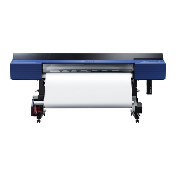
VG-640 — 64-inch model VG-540 — 54-inch model Also, most of the figures in this document depict the VG-640. Company names and product names are trademarks or registered trademarks of their respective holders. Copyright © 2015-2016 Roland DG Corporation http://www.rolanddg.com/... -
Page 4: Installation Environment
1. Installation Environment Deciding On an Installation Site Install the machine in a quiet, stable location offering good operating conditions. An unsuitable location can cause accidents, fire, faulty operation, or breakdown. WARNING Install the machine in a location that is level, stable, and able to bear the weight of the machine. -
Page 5: Temperature And Humidity
1. Installation Environment Temperature and Humidity Maintain the specified temperature and humidity even when the machine is not in use. Failure to do so may result in malfunction. During operation: Temperature 20 to 32°C (68 to 90°F), humidity: 35 to 80%RH (no condensation) During non-operation: Temperature 5 to 40°C (41 to 104°F), humidity: 20 to 80%RH (no condensation) Installation Space The space shown in the figure is required in order to use this machine. -
Page 6: Included Items
2. Included Items The following items are included with the machine. Make sure they are all present before proceeding. Arms Stand legs Power cord (1) Casters (2) (1 each for right and left) (1 each for right and left) Stand stay (1) Shafts (2) Middle pinch rollers * ** Media holders/retaining... -
Page 7: Assembly And Ink Filling
3. Assembly and Ink Filling Checks before Operations CAUTION Unloading and emplacement are operations that must be performed by 8 persons or more. Tasks that require undue effort when performed by a small number of persons may result in physical injury. Also, if dropped, such items may cause injury. Completed Drawing Necessary Tools Hexagonal wrench... -
Page 8: Step 1: Assembling The Stand And Attaching The Printer
3. Assembly and Ink Filling Step 1 : Assembling the Stand and Attaching the Printer Procedure Place the caster on the stand leg. Place the stand leg with the tabletop plate facing down, and then place the caster on top of the stand leg. - Page 9 3. Assembly and Ink Filling Fully tighten the bolts in the 4 upper locations and then in the 4 locations on the sides. Use the pipe when tightening the bolts in the upper locations. When tightening the bolts fully, tighten them securely.
- Page 10 3. Assembly and Ink Filling Lightly tighten the bolts in the order of Use a washer for each bolt. Tighten temporarily Bolts: 6 Washers: 6 Fully tighten the bolts in the order of Before tightening the bolts, check once more that the 2 stand legs are parallel. If the inside of the stand stay is touching the L-shaped brackets and the stand legs, the stand legs will be parallel.
- Page 11 3. Assembly and Ink Filling Place the printer unit on the stand, and lightly tighten its bolts in the order of Set the assembled stand upright, and then fix the printer unit to it by tightening the bolts (8 locations in total).
-
Page 12: Step 2: Installing The Media Holders
3. Assembly and Ink Filling Step 2 : Installing the Media Holders Procedure Lightly tighten the bolts on the left side of the stand as seen from the rear of the printer. Tighten the bolts in the holes on the left side of the stand until you can see approximately 10 mm (0.4 inches) of their threads. - Page 13 3. Assembly and Ink Filling Fully tighten the bolts in the order of (stand rear), (stand side). Tighten fully Bolts: 4 Attach the other arm to the right side as seen from the rear of the machine. Place the shafts on the arms. Pass the left media holder onto the shafts.
- Page 14 3. Assembly and Ink Filling Move the left media holder to the left side of the shafts, and then tighten the retaining screw. In the same manner, pass the right media holder onto the shafts, and then tighten the retaining screw. Attach the shaft clamps to secure the shafts in place.
-
Page 15: Step 3: Installing The Drain Bottle
3. Assembly and Ink Filling Step 3 : Installing the Drain Bottle Procedure Remove the bottom plug. Use caution, because discharged fluid used in the inspection when the printer was shipped may remain. Bottom plug Install the drain bottle. Screw the drain bottle into the hole where the bottom plug was attached. Use caution to turn the bottle without applying excessive force. -
Page 16: Step 4: Removing The Retainers
3. Assembly and Ink Filling Step 4 : Removing the Retainers IM PORTA NT • Make sure to remove all the retainers. If any remain on the machine, faulty operation or breakdown may occur when the power is switched on. •... -
Page 17: Step 5: Adjusting The Ink Tube And Affixing A Label (Only When Using Four Colors)
3. Assembly and Ink Filling Step 5 : Adjusting the Ink Tube and Affixing a Label (Only When Using Four Colors) M E MO This step is only required when using the machine with four colors: CMYK. If you are using the machine with seven or eight colors, proceed to "Step 6: Connecting the Cables."... -
Page 18: Step 6: Connecting The Cables
3. Assembly and Ink Filling Step 6 : Connecting the Cables Procedure Insert the cable clamp. Connect both the power cord and the Ethernet cable (commercially available). Use a power plug adapter if the electrical outlet is a two-prong outlet. WARNING Perform this task with all power switches left switched off. -
Page 19: Step 7: Initial Settings
3. Assembly and Ink Filling Step 7 : Initial Settings Procedure Close the front cover. Switch on the main power switch. Open the ink slot cover. Remove all the pouch trays. - Page 20 3. Assembly and Ink Filling Remove the pouch tray from the cleaning liquid slot. Open the panel cover, and then hold down [MENU] and press the sub power switch. Press [ ] or [ ] to select the language you want, and then press [ENTER]. MENU LANGUAGE ENGLISH Press [ ] or [ ] to select the unit of measurement you want (for length), and then press...
-
Page 21: Step 8: Ink Filling
TR cleaning liquid." • TR cleaning liquid pouch to be used on P. 24, "4. Fill the machine with TR cleaning liquid." is needed to be purchased separately. Purchase them from your authorized Roland DG Corp. dealer. Items used in this procedure... - Page 22 3. Assembly and Ink Filling The screen shown below appears, and then the machine starts the preparations for the ink filling. The remaining time for the procedure is displayed on the screen. (The display shown below is an example. "20:00" = "20 minutes and 00 seconds") FILLING INK...
- Page 23 3. Assembly and Ink Filling The screen shown below appears. FILLING INK... >>>>> XX:XX When the screen shown below appears, remove the pouch tray from the slot whose number is displayed. 7 colors (CMYKLcLmLk) 4 colors (CMYK) REMOVE CL-LIQUID REMOVE CL-LIQUID The screen shown below appears.
- Page 24 3. Assembly and Ink Filling If the following message is displayed partway through the operation, remove the drain bottle and discard the discharged fluid. EMPTY DRAIN BOTTLE CAUTION Before you detach the drain bottle, be sure to wait for the screen to display [EMPTY DRAIN BOTTLE].
- Page 25 3. Assembly and Ink Filling Fill the machine with ink. When the screen shown below appears, remove the drain bottle and discard the dis- charged fluid. EMPTY DRAIN BOTTLE CAUTION Before you detach the drain bottle, be sure to wait for the screen to display "EMPTY DRAIN BOTTLE."...
- Page 26 3. Assembly and Ink Filling When the screen shown below appears, set the pouch tray in which you have set an ink pouch in the ink slot whose number is flashing. When using four colors (CMYK), set the pouch trays in the "2, 4, 6, 8" ink slots. Then, when "1, 3, 5, 7" is displayed, set the remaining pouch trays in the remaining ink slots.
-
Page 27: Filling Ink
3. Assembly and Ink Filling The screen shown below appears. FILLING INK... >>>>> XX:XX Close the ink slot cover. When the screen shown below appears, remove the drain bottle and discard the dis- charged fluid. EMPTY DRAIN BOTTLE CAUTION Before you detach the drain bottle, be sure to wait for the screen to display "EMPTY DRAIN BOTTLE."... -
Page 28: Installing The Cutting Tool
4. Installing the Cutting Tool CAUTION Be sure to perform operations as specified by the instructions, and never touch any area not specified in the instructions. Failure to observe these instructions may cause the machine to move suddenly, resulting in injury. CAUTION Never touch the tip of the blade. -
Page 29: Step 2: Installing The Cutting Tool
4. Installing the Cutting Tool Step 2 : Installing the Cutting Tool Enter "REPLACE KNIFE" menu. Press [MENU]. Press [ ] several times to display the screen shown below. MENU SUB MENU Press [ ] once, and then press [ ] several times to display the screen shown below. SUB MENU MAINTENANCE Press [ ] once, and then press [ ] several times to display the screen shown below. - Page 30 4. Installing the Cutting Tool Install the cutting tool. Loosen the cutting carriage screw. Install the cutting tool in the cutting carriage. Not OK Tighten the screw. Close the front cover. Press [ENTER]. Important note on the handling and use of the cutting carriage Leave the cutting-carriage screw loose when no cutting tool is installed.
-
Page 31: Network Settings
5. Network Settings The examples used in the procedures for making the settings described in this section assume you are using one computer and one machine. The settings used in this section are merely example settings. The procedures and setting values described here may not be suitable for all operating environments. - Page 32 5. Network Settings Click [Properties]. The [Ethernet Properties] dialog box appears. (On Windows 7, the [Local Area Connection Status] dialog box appears.) If the [User Account Control] dialog box appears, click [Continue]. Select [Internet Protocol Version 4 (TCP/IPv4)], and then click [Properties]. If the [Internet Protocol] check box is clear, select it.
-
Page 33: Step 2: Make The Network Settings On The Printer
5. Network Settings Select [Use the following IP address]. Enter the information as shown below, and then click [OK]. Item Address to enter IP address 192.168.0.XXX Subnet mask 255.255.255.0 Here, "XXX" can be any number from 1 to 254. However, be sure to specify a number that is different from the numbers used for other computers and devices. - Page 34 5. Network Settings Press [ ] 3 times to display the screen shown below. IP ADDRESS 000.000.000.000 Press [ ] or [ ] to select the address number. Press [ ]. Repeat to set [IP ADDRESS] (192.168.000.XXX). Here, "XXX" can be any number from 001 to 254. However, be sure to specify a number that is different from the setting you made in Step 1 and from the numbers used for other computers and devices.
- Page 35 5. Network Settings When you have finished making the setting, press [ENTER]. Press [ ] to go back to the screen shown below. NETWORK SUBNET MASK If you are using the computer and the machine on a one-to-one basis, this completes the settings to make on the printer.
-
Page 36: Step 3: Make The Port Settings For The Software Rip
RIP. Confirming that a network connection has been established Roland VersaWorks Dual (hereinafter referred to as "VersaWorks Dual") You can use the printing-test feature to check whether the connection to the network has been established.