
Related Manuals for tousek PULL T24


Summary of Contents for tousek PULL T24
- Page 1 Mounting and installation manual Sliding gate operators PULL T24, -T24speed V 2.6.004 Safety Sensor...
-
Page 2: Table Of Contents
Declaration of incorporation .......................... 31 This manual is the sole property of the TOUSEK Ges.m.b.H. and may not be made available to competitors. All rights reserved. No part of it may be reproduced without our prior written permission. We will not accept liability for any claims resulting from misprints or errors. This edition of the manual replaces all earlier publications of the same. -
Page 3: General Warning And Safety Details
EU and in the individual countries have to be strictly followed. • The TOUSEK Ges.m.b.H. cannot be held liable for any claims resulting from disregards of the laws and standards in force during the installation and operation. -
Page 4: Notes, General Characteristics, Function, Technical Data
The installation of the PULL T24, -T24speed is possible for new or already exsting sliding gates in a simple and fast way. - Page 5 ATTENTION ! • ATTENTION: Mechanical limits are necessary! • ATTENTION: the sliding gate operator PULL T24, -T24speed has been developed and designed for the auto- mation of horizontally travelling sliding gates. Gates on sloping tracks (i.e. gates which follow an inclined, non-horizontal, travel path) must not be automated without additional safety devices (which make sure that the gate cannot start moving on its own from any gate position).
- Page 6 (PHZ) PULL T24: Z16M4, r36 gear wheel cable ground plate (4a) slotted holes (4x) for connection on the ground steel gear rack Dimensions in mm Foundation 18,5 18,5 13,5 - 6 - tousek / E_PULL-T24-T24speed_49002410 / 06. 08. 2019...
- Page 7 Apart from that the gear rack • Do not weld the individual gear rack elements elements together! - 7 - tousek / E_PULL-T24-T24speed_49002410 / 06. 08. 2019...
-
Page 8: Mounting
Handle in picture shows unlocked position new learning of end positions is not necessary). 2.4 Exchanging the lock half cylinder Sliding gate operator PULL T24, -T24speed • Remove the screw protection cap and turn out the screw (S). • Turn the cylinder protection cap down, insert the key, turn it approx. -
Page 9: Control Unit, Overview
Control board Sliding gate operator PULL T24, -T24speed Overview of the control unit Important The optional „tousek-connect“ or the „tousek service interface“ must be connected with socket (D)! Attention During connection, adjustment and maintenance works please take care, that the electronic circuit board won´t be damaged by moisture (rain). -
Page 10: Warnings - Connection Works
3.1 Terminal assignment Sliding gate operator PULL T24, -T24speed Attention • Before taking off the control cover, the • The product is not suitable for installation in explosion- mains switch must be turned off! hazardous areas. • If the control is power supplied, its inner part is under •... -
Page 11: Programming, Structure Of The Menu
3.2 Adjustments - overview Sliding gate operator PULL T24, -T24speed Programming buttons Adjustment - overview • Before starting the programming, please choose the language. Use the buttons to choose menu lan- guage and confirm with • Note: Language selection can also be chosen by pressing the ESC button ( ) for 5s, from any position in menu. - Page 12 The menu points courtyard lamp and control lamp will only appear on display if in menu „Additional module" courtyard lamp/control lamp is selected. ENTER integr. control board for sliders PULL T24, -T24speed - 12 - tousek / E_PULL-T24-T24speed_49002410 / 06. 08. 2019...
-
Page 13: 3.3 Connections And Adjustments
3.3 Connections and adjustments Sliding gate operator PULL T24, -T24speed Warning notes • Before taking off the control cover, the • The product is not suitable for installation in explosion- mains switch must be turned off! hazardous areas. • If the control is power supplied, its inner part is under •... - Page 14 The stop input has no emergency stop function! - In order to ensure the emergency stop function, provide the supply line with an all-pole disconnecting emergency stop switch, that locks after actuation! - 14 - tousek / E_PULL-T24-T24speed_49002410 / 06. 08. 2019...
-
Page 15: Safety
Photocell Tousek LS 26 as safety device 12/24V 12/24V NC C NO Important • Jumper J of transmitter and receiver has to be adjusted in the same way. - 15 - tousek / E_PULL-T24-T24speed_49002410 / 06. 08. 2019... - Page 16 Photocell Tousek LS 41 as safety device 2 Photocells Tousek LS 41 as safety device transmitter receiver transmitter 1 receiver 1 Deactivation of SYNC function • The SYNC function with LS41 is SYNC not possible with this control unit. For deactivation of SYNC function, the jumpers J of both transmitters have to be connected (see picture).
- Page 17 not active: to be selected if the contact strip of side safety sensing edge should NOT be evaluated. • Connection and detailed information of radio transmission system TX 310 see according manual. • Connection and detailed information of inductive system TX 400i see according manual. - 17 - tousek / E_PULL-T24-T24speed_49002410 / 06. 08. 2019...
- Page 18 • The photocell self-test can only be deactivated by selecting „not active“. • The deactivation of the self-test function is only permitted if the safety installations correspond to the category 3 ! - 18 - tousek / E_PULL-T24-T24speed_49002410 / 06. 08. 2019...
-
Page 19: Motor
By deleting the limit positions in the menu „DIAGNOSIS / delete positions“ the adjusted value for „limit position OPEN“ will be deleted as well. The factory setting -5 will be saved. Attention At force adjustment the valid safety regulations and standards have to be strictly followed ! - 19 - tousek / E_PULL-T24-T24speed_49002410 / 06. 08. 2019... -
Page 20: Operating Mode
If the gate is in partial open position and „permanent open in automatic mode“ is selected, so it is possible to adjust permanent partial open for this cycle by giving an impulse via pedestrian button. Permanent partial open can be finished analogous to the above described method. - 20 - tousek / E_PULL-T24-T24speed_49002410 / 06. 08. 2019... -
Page 21: Lights/Lamps
If the gate is closed, the pilot lamp expires illuminates in open position: Pilot lamp is illuminated as soon as the gate has reached end position open. - 21 - tousek / E_PULL-T24-T24speed_49002410 / 06. 08. 2019... - Page 22 • On the terminals 70/71 a control lamp (K) can be connected: 24Vd.c., max. 2W • Contact load: 24Va.c./d.c., max. 10W – 12 13 70 71 90 91 92 93 - 22 - tousek / E_PULL-T24-T24speed_49002410 / 06. 08. 2019...
-
Page 23: Diagnosis
HOURS : MINUTES : SECONDS $$$$$$$$$$$$$$$$ T -00 00:00:00.0 $$$$$$$$$$$$$$$$ Event Type of event Status Sensor Diagnosis Degree and signal strenght of rotation speed sensor is shown on display. - 23 - tousek / E_PULL-T24-T24speed_49002410 / 06. 08. 2019... -
Page 24: Connection Of Radio Receiver
• The product may only be used in accordance with its original purpose, for which it has been exclusively designed, and which is described in these installation and operating instructions (especially children have to be instructed). The TOUSEK Ges.m.b.H. rejects any liability if the product is used in any way not fully conforming to its original purpose as stated herein. -
Page 25: Initial Operation
Putting into operation Sliding gate operator PULL T24, -T24speed Important: preparation works • Connect control panels, safety devices to the motor in compliance with the safety regulations. Attention: if no stop switch is connected then the terminals 31/37 have to be bridged. - Page 26 This would $$$$$$$$$$$$$$$$ side safety edge $$$$$$$$$$$$$$$$ lead to an interruption of the programming process. With the use of a backup battery please connect now the battery! (point 5.1) - 26 - tousek / E_PULL-T24-T24speed_49002410 / 06. 08. 2019...
-
Page 27: 5.1 Battery Connection
5.1 Battery connection Sliding gate operator PULL T24, -T24speed Important for use with emergency battery • The motor can be equipped with an additional optional battery (NB), which can be integrated into the operator and can be fixed with boltable bracket (B). -
Page 28: Error Diagnosis
Troubleshooting guide Sliding gate operator PULL T24, -T24speed Error possible reason solution stop-button not connected or not Stop-button (Kl. ) connect or bridge > Display: „Stop-button released“ bridged use status display for help check correct connection hence Display: „Photocell released“... -
Page 29: Cable Plan
- 29 - tousek / E_PULL-T24-T24speed_49002410 / 06. 08. 2019... -
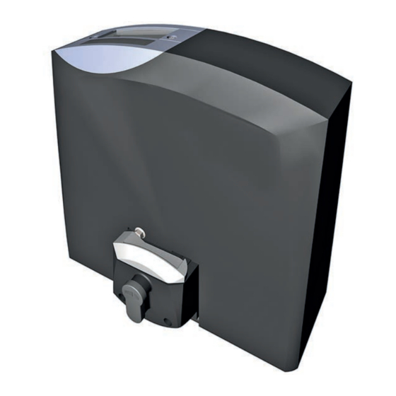
Page 30: Dimensioned Drawing
Dimensioned drawing Sliding gate operator PULL T24, -T24speed • Dimensions in mm (1) lockable emergency release (euro standard cylinder) (2) gear wheel 206,5 (3) cable entrance (4) ground plate (4a) slotted holes (4x) for mounting on foundation (5) display for programming... -
Page 31: Declaration Of Incorporation
Date/ Signature TOUSEK Ges.m.b.H., A1230 Wien, Zetschegasse 1, Österreich is authorized to compile the technical documentation. The incomplete machine cannot be put into service, until it... - Page 32 Buitenheide 2A/ 1 Tel. +32/ 11/ 91 61 60 your service partner: Fax +32/ 11/ 96 87 05 info@tousek.nl Tousek Sp. z o.o. Poland PL 43-190 Mikołów (k/Katowic) Gliwicka 67 Tel. +48/ 32/ 738 53 65 Fax +48/ 32/ 738 53 66 info@tousek.pl...
Need help?
Do you have a question about the PULL T24 and is the answer not in the manual?
Questions and answers