Table of Contents
Advertisement
Quick Links
Advertisement
Table of Contents

Related Manuals for Contura C 690


Summary of Contents for Contura C 690
- Page 1 Installation instruction C 690 www.contura.eu...
- Page 2 350° C for both top connection directly upwards and connection directly backwards from the rear of the stove. Contura 690 is a Swan marked stove. NIBE was the first stove manufacturer in Sweden to commit to Swan marking their stoves.
-
Page 3: Table Of Contents
A warm welcome to the Contura family. We hope you will get a great deal of pleasure from your new stove. As a new owner of a Contura stove you have secured a product with timeless design and long service life. -
Page 4: Local Authority
FACTS Technical details Important to remember! Installation by authorised Structural support Output 3–9kW Nominal output 6kW (approx1,5 kg/hour) technician Check that the wood joists are strong Efficiency up to 80% enough to bear the weight of the stove This manual contains instructions about and chimney. -
Page 5: Unpacking
UNPACKING Unpacking Leave the stove body screwed in place on the pallet. Supplied components must be placed to one side. Dismantle all the loose components from the stove body (fire-bars, fire-box surround, grate disc, cast-iron fire-bed and ash-pan). Then remove the stove body from the pallet. -
Page 6: Connection To Chimney
CHIMNEY Connection to chimney • The stove meets the requirements for connecting to chimneys • A flue with sharp bends and horizontal routing reduces the dimensioned for 350°C flue gas temperature. draught in the chimney. Maximum horizontal flue is 1 m, on the condition that the vertical flue length is at least 5 m. -
Page 7: Supply Of Combustion Air
SUPPLY AIR/ACCESSORY Supply of combustion air Combustion air can be provided directly via a duct from outside, or indirectly via a vent in the outer wall of the room where the stove is to be placed. Some installation alternatives are shown to the right. Before fitting an air supply duct to the air inlet, the heat reflector under the stove body must be removed. -
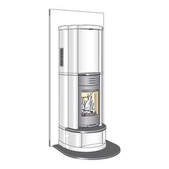
Page 8: Installation Distances
INSTALLATION DISTANCES Installation distances C 690 When installing the base plate (see page 28) check that the installation approx 2055 mm above the floor, where the fully insulated chimney distances given in the figures below are not fallen below. When top takes effect. -
Page 9: Positioning The Base Plate
ASSEMBLY Positioning the base plate Position the base plate the correct distance from the wall as specified on page 25. The centre of the hole in the base plate is inline with the centre of the chimney. ”When installing against non-flammable walls or protective screens, position the base plate against the wall. -
Page 10: Installing The Lighting Cable
ASSEMBLY Installing the lighting cable Thread on the black grommet bushing onto the cable. Measure out the centre of the wall behind the masonry chimney. Draw a line 150 mm to the left or the right of the centre. The heat resistant lighting cable will be positioned along this line. -
Page 11: Installing The Back Plate
ASSEMBLY Installing the back plate Break off the mounting fixtures from the lower edge of the Lay the flat left-hand section of the back plate on the floor. right-hand section of the back plate. Installation is simplified if the back plate is mounted on some boards or polystyrene strips. - Page 12 ASSEMBLY Screw the top frame into place on the back plate. Bend the lugs on the top frame down 90° using pliers. If the stove is rear connected the partly punched hole is cut from the back plate. Hang the back plate with the top frame on the stove body.
-
Page 13: Installing Concrete Surround And Top Connection
ASSEMBLY Installing concrete surround and top connection Check that there are no hairline cracks in the concrete plate before the back plate and the concrete. The space between the stove and starting installation. the protective screen behind it shall be filled with the acrylic filler During heating the metal sheet in the hearth plate expands. - Page 14 ASSEMBLY Because of the restricted space it is easier to paint the front edge of the side plate before installation. Drill a Ø5 mm hole at the bottom in a corner of one of the side plates. The hole is for the grommet for the lighting cable.
- Page 15 ASSEMBLY Clean the surfaces to be bonded. Apply a bead of silicone to the lower side plate and a thick bead of silicone at the bottom of the groove on the inside of the upper side plate. Position the upper side plate on the lower side plate. Angle in the upper side plate and hook it into place with the installation fixture so that it will not fall.
- Page 16 ASSEMBLY For top connection the start pipe must be insulated using 30 Place the eight olivine stones on the top frame. Check that they mm thick insulation above the sealing plate. Pull the insulation are stable. down over the start pipe but not the whole way. Refer to the chimney’s installation instructions to install the chimney.
- Page 17 ASSEMBLY If the stove is top connected, the insulation around the start pipe is pushed down towards the sealing insulation. Place the stop washer on the ridge around the start pipe and thread the transfer insulation down. Install the first chimney module and the front half of the ceiling seal and moulding.
- Page 18 ASSEMBLY The plinth can be mounted in three different ways, as a shallow plinth niche, as a deep plinth niche or as a log box. When installing, apply a bead of silicone between the plates. Apply silicone to the side plate and move the marble shelf into Place the cover bow on the shelf under the hatch and push it position.
- Page 19 ASSEMBLY Install the convector fascia or the oven in accordance with the instructions for the various optional extras on pages 44. This must be done before the recessed shelf is installed. Apply silicone to the top frame and move the marble recessed shelf into position.
- Page 20 ASSEMBLY If the stove is top connected the partly punched hole is cut from Position the top plate, insert the cable from the side into the the top plate. lead-in hole and press the grommet into the lead-in hole. Bond the top plate with a few drops of silicone.
- Page 21 ASSEMBLY The spring pressure against the lamp can easily be adjusted if the lamp jumps out of the lamp holder too easily. The spring pressure is released by bending out the spring mountings on the right edge on both sides. Apply large drops of silicone on the sides in the holes for the Install the light screen over the top plate.
-
Page 22: Installing Oven (Option)
ASSEMBLY Installing oven (option) Remove the screw on the top hinge of the door. Replace this Hold the oven door in place on the threaded pin. Hook the top screw with the threaded hexagonal pin. This pin serves as the hinge in place and loosely tighten one of the screws. - Page 24 NIBE AB · Box 134 · 285 23 Markaryd · Sweden www.contura.eu Contura reserves the right to change colours, materials, dimensions and models at any time without special notice. Your dealer can give you the most up 611842 IAV SE-EX C690 - 6 to date information.
Need help?
Do you have a question about the C 690 and is the answer not in the manual?
Questions and answers