Table of Contents

Related Manuals for Fujitsu WGYA050DG6


Summary of Contents for Fujitsu WGYA050DG6
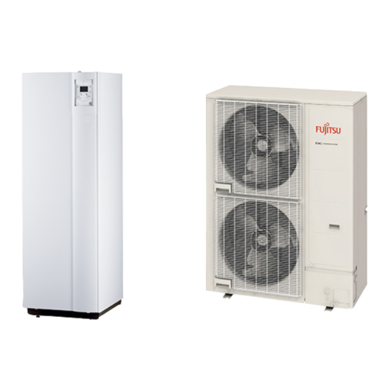
- Page 1 DTW_SDI003E_01 DESIGN & TECHNICAL MANUAL COMFORT SERIES ( Single phase type ) HIGH POWER SERIES ( Single phase type ) HIGH POWER SERIES ( 3 phase type ) Air to Water Split DHW INNOVATIVE SOLUTION OF DOMESTIC HEATING Integrated type...
- Page 2 C O N T E N T S OUTDOOR UNIT COMFORT SERIES Single phase type: WOA060LFCA, WOA080LFCA, WOA100LFTA HIGH POWER SERIES Single phase type: WO G112LCTA, WO G140LCTA 3 phase type: WO K112LCTA, WO K140LCTA, WO K160LCTA HYDRAULIC UNIT COMFORT SERIES...
- Page 3 COMBINATIONS Class OUTDOOR UNIT HYDRAULIC UNIT 5.0 kW WOA060LFCA WGA050DG6 6.0 kW WOA060LFCA 8.0 kW WOA080LFCA WGA100DG6 10.0 kW WOA100LFTA 11.0 kW WOG112LCTA WGG140DG 14.0 kW WOG140LCTA 11.0 kW WOK112LCTA WGHG140DG 14.0 kW WOK140LCTA WGYK160DG9 16.0 kW WOK160LCTA...
- Page 4 1. OUTDOOR UNIT SINGLE PHASE TYPE : WO A060LFCA WO A080LFCA WO A100LFTA DTW_1SP005E_01--CHAPTER01 2016.02.18...
-
Page 5: Table Of Contents
C O N T E N T S OUTDOOR UNIT 11 FEATURES 11111111111111111111111111111111111111111111111111111111111111111111111111111111111111111111111111111111111111111OU01 - 01 21 SPECIFICATIONS 1111111111111111111111111111111111111111111111111111111111111111111111111111111111111111111111111OU01 - 04 2-11 NOMINAL CAPACITY AND NOMINAL INPUT 1111111111111111111111111111111111111111111111111111OU01 - 04 2-21 TECHNICAL SPECIFICATIONS 1111111111111111111111111111111111111111111111111111111111111111111111111111OU01 - 05 2-31 PRODUCT FICHE 1111111111111111111111111111111111111111111111111111111111111111111111111111111111111111111111111111OU01 - 06 2-41 PRODUCT INFORMATION 1111111111111111111111111111111111111111111111111111111111111111111111111111111111111OU01 - 07 2-51 ELECTRICAL SPECIFICATIONS... -
Page 6: Features
FEATURES „ „ MODELS : WOA060LFCA WOA080LFCA WOA100LFTA WOA060LFCA WOA100LFTA WOA080LFCA „ „ HIGH PERFORMANCE High efficiency & Comfort „ High COP Optimized hot water control is realized by DC inverter technology. Split Type model allows flexible installations. Ambient air Co-axial Heat Exchanger Hydraulic unit Outdoor unit... -
Page 7: Operation Range
High leaving water temperature Maximum leaving water temperature is 55°C without backup heater. Hot water supply temperature can be maintained even at –10°C outdoor temperature. Wide operation range Possible to operate heating under -20°C 35°C outdoor temperature 0°C -25°C Outdoor temperature Outdoor unit / Single phase - (OU01 - 02) -... - Page 8 „ „ WIDE COMFORT Wide comfort by The clean energy produced by reliably delivers “comfort” to diverse spaces in the home up to the living room, bedrooms, bath and swimming pool. Domestic hot water Radiator Domestic hot water tank Hot water supply Indoor unit Take thermal energy Swimming pool...
-
Page 9: Specifications
SPECIFICATIONS 2-11 NOMINAL CAPACITY AND NOMINAL INPUT Model name (Outdoor unit) WO A060LFCA WO A080LFCA WO A100LFTA POWER SOURCE 1Ø 230V ~ 50Hz Minimum 1.75 1.75 1.75 3.20 Heating capacity Nominal 4.50 6.00 7.50 10.00 +7°C/+35°C Maximum 7.02 7.83 9.20 13.45 floor heating Input power... -
Page 10: Dimensions
2-21 TECHNICAL SPECIFICATIONS Model name (Outdoor unit) WOA060LFCA WOA080LFCA WOA100LFTA BEIGE Colour Apporoximate colour of MUNSELL 10YR 7.5/1.0 Enclosure Material Steel sheet 620 × 790 × 290 830 × 900 × 330 Dimensions (H x W x D) Gross 712 × 935 × 400 970 ×... -
Page 11: Product Fiche
2-31 PRODUCT FICHE Product fiche according to Commission Delegated Regulation (EU) 811/2013 WSYA050DG6 WGYA050DG6 WSYA100DG6 WGYA100DG6 Hydraulic unit WSHA050DG *1 WGHA050DG *1 WSHA100DG *1 WGHA100DG *1 Model WOYA060LFCA WOYA060LFCA Outdoor unit WOHA060LFCA WOHA060LFCA Temperature application °C Declared load profile Seasonal space heating energy efficiency class... -
Page 12: Product Information
η Daily fuel consumption Not applicable fuel FUJITSU GENERAL (EURO) GmbH Contact details Werftstraße 20, D-40549 Düsseldorf, F. R. Germany *1 : Optional electrical back up heater consumption is taken into account in the performance calculation. *2 : For heat pump space heaters and heat pump combination heaters, the rated heat output Prated is equal to the design load for heating... - Page 13 η Daily fuel consumption Not applicable fuel FUJITSU GENERAL (EURO) GmbH Contact details Werftstraße 20, D-40549 Düsseldorf, F. R. Germany *1 : Optional electrical back up heater consumption is taken into account in the performance calculation. *2 : For heat pump space heaters and heat pump combination heaters, the rated heat output Prated is equal to the design load for heating...
- Page 14 „ „ ENERGY EFFICIENCY VALUE WSYA050DG6 WSYA100DG6 WSYA100DG6 WSYA100DG6 Hydraulic unit WSHA050DG WSHA100DG WSHA100DG WSHA100DG Model name WOYA060LFCA WOYA060LFCA WOYA080LFCA WOYA100LFTA Outdoor unit WOHA060LFCA WOHA060LFCA WOHA080LFCA WOHA100LFTA Heating appilcation °C S e as o n a l s p ac e h e at i n g e n e r g y efficiency of heat pump „...
-
Page 15: Electrical Specifications
2-51 ELECTRICAL SPECIFICATIONS Model name (Outdoor unit) WOA060LFCA WOA080LFCA WOA100LFTA Available voltage range 198-264 Voltage Power supply Frequency *1) Max. operating current Heating 12.5 17.5 18.5 Main fuse (Circuit breaker) Current *2) Wiring spec. Power cable mm² 3.5-4.0 For power supply Wiring connections For connection with *3) Quantity... -
Page 16: Dimensional Drawing
DIMENSIONS 3-11 DIMENSIONAL DRAWING „ „ A060LFCA, WOA080LFCA MODELS : WO (Unit : mm) 4Holes Ø11 Bottom view Drain hole Outdoor unit / Single phase - (OU01 - 11) -... - Page 17 „ „ A100LFTA MODEL : WO (Unit : mm) Outdoor unit / Single phase - (OU01 - 12) -...
-
Page 18: Installation Place
3-21 INSTALLATION PLACE „ „ A060LFCA, WOA080LFCA MODELS : WO (unit: mm) 300 or more „ „ A100LFTA MODEL : WO Outdoor unit / Single phase - (OU01 - 13) -... -
Page 19: Piping Diagram
PIPING DIAGRAM „ „ A060LFCA, WOA080LFCA MODELS : WO Heating emitter (Floor heating, radiator) Indoor unit Refrigerant – water heat exchanger Heating cycle direction of flow Heat exchange sensor Muffler 2-way valve Discharge Dedicated temperature sensor compressor for injection port mounting 3-way valve Strainer... -
Page 20: Wiring Diagram
WIRING DIAGRAM 5-11 WIRING DIAGRAM „ „ A060LFCA MODEL : WO Outdoor unit / Single phase - (OU01 - 15) -... - Page 21 „ „ A080LFCA MODEL : WO Outdoor unit / Single phase - (OU01 - 16) -...
- Page 22 „ „ A100LFTA MODEL : WO Outdoor unit / Single phase - (OU01 - 17) -...
-
Page 23: Capacity Tables
CAPACITY TABLES 6-11 HEATING CAPACITY : WOA060LFCA (4.5kW type) „ „ MODEL 30°C 35°C 40°C 45°C 50°C 55°C ― ― ― ― ― ― ― ― ― -20°C 2.87 1.25 2.30 2.87 1.37 2.09 2.73 1.46 1.87 ― ― ― ―... - Page 24 : WOA060LFCA (6.0kW type) „ „ MODEL 30°C 35°C 40°C 45°C 50°C 55°C ― ― ― ― ― ― ― ― ― -20°C 3.72 1.68 2.21 3.67 1.78 2.06 3.60 1.92 1.87 ― ― ― ― ― ― ― ― ―...
- Page 25 „ „ MODEL : WOA080LFCA 30°C 35°C 40°C 45°C 50°C 55°C ― ― ― ― ― ― ― ― ― -20°C 4.49 2.03 2.21 4.26 2.13 2.00 4.03 2.21 1.82 ― ― ― ― ― ― ― ― ― -19°C 4.91 2.21 2.22 4.66...
- Page 26 „ „ MODEL : WOA100LFTA 30°C 35°C 40°C 45°C 50°C 55°C ― ― ― ― ― ― ― ― ― -20°C 5.97 2.57 2.32 5.89 2.86 2.06 5.60 3.05 1.84 ― ― ― ― ― ― ― ― ― -19°C 6.41 2.72 2.36 6.31...
- Page 27 6-21 COOLING CAPACITY : WOA060LFCA (4.5kW type) „ „ MODEL 6 °C 7 °C 10 °C 13 °C 15 °C 18 °C 22 °C COP CC COP CC COP CC COP CC COP CC COP CC 20 °C 2.80 0.93 3.02 2.90 0.91 3.19 3.20 0.85 3.75 3.50 0.79 4.44 3.70 0.74 4.97 4.00 0.68 5.86 4.40 0.61 7.22 21 °C 2.80 0.94 2.98 2.90 0.93 3.12 3.20 0.87 3.68 3.50 0.81 4.32 3.70 0.77 4.81 4.00 0.71 5.63 4.40 0.64 6.88 22 °C 2.80 0.96 2.92 2.90 0.94 3.09 3.20 0.89 3.60 3.50 0.83 4.22 3.70 0.79 4.68 4.00 0.74 5.41 4.40 0.67 6.57 23 °C 2.80 0.98 2.86 2.90 0.96 3.02 3.20 0.91 3.52 3.50 0.86 4.07 3.70 0.81 4.57 4.00 0.77 5.19 4.40 0.71 6.20...
- Page 28 : WOA060LFCA (6.0kW type) „ „ MODEL 6 °C 7 °C 10 °C 13 °C 15 °C 18 °C 22 °C COP CC COP CC COP CC COP CC COP CC COP CC 20 °C 3.60 1.10 3.27 3.70 1.10 3.37 4.10 1.04 3.94 4.50 0.98 4.59 4.80 0.93 5.14 5.20 0.89 5.86 5.70 0.84 6.77 21 °C 3.60 1.13 3.19 3.70 1.12 3.30 4.10 1.07 3.83 4.50 1.01 4.46 4.80 0.97 4.95 5.20 0.92 5.65 5.70 0.88 6.48 22 °C 3.60 1.15 3.13 3.70 1.14 3.25 4.10 1.09 3.76 4.50 1.04 4.33 4.80 1.00 4.80 5.20 0.96 5.42 5.70 0.91 6.26 23 °C 3.60 1.17 3.08 3.70 1.16 3.19 4.10 1.12 3.66 4.50 1.07 4.21 4.80 1.03 4.66 5.20 0.99 5.25 5.70 0.95 6.00...
- Page 29 „ „ MODEL : WOA080LFCA 6 °C 7 °C 10 °C 13 °C 15 °C 18 °C 22 °C COP CC COP CC COP CC COP CC COP CC COP CC 20 °C 4.90 1.44 3.41 5.10 1.42 3.60 5.70 1.36 4.18 6.20 1.31 4.74 6.60 1.26 5.25 7.10 1.21 5.87 7.80 1.15 6.81 21 °C 4.90 1.46 3.36 5.10 1.44 3.54 5.70 1.40 4.07 6.20 1.35 4.59 6.60 1.30 5.08 7.10 1.26 5.63 7.80 1.20 6.50 22 °C 4.90 1.49 3.29 5.10 1.47 3.47 5.70 1.43 3.99 6.20 1.38 4.49 6.60 1.34 4.93 7.10 1.30 5.46 7.80 1.25 6.24 23 °C 4.90 1.52 3.22 5.10 1.50 3.40 5.70 1.46 3.90 6.20 1.42 4.37 6.60 1.39 4.75 7.10 1.35 5.26 7.80 1.31 5.95...
- Page 30 „ „ MODEL : WOA100LFTA 6 °C 7 °C 10 °C 13 °C 15 °C 18 °C 22 °C COP CC COP CC COP CC COP CC COP CC COP CC 20 °C 5.90 1.68 3.51 6.10 1.66 3.68 6.80 1.60 4.26 7.40 1.52 4.86 7.90 1.48 5.33 8.50 1.44 5.92 9.40 1.38 6.83 21 °C 5.90 1.72 3.43 6.10 1.69 3.61 6.80 1.64 4.15 7.40 1.57 4.71 7.90 1.53 5.16 8.50 1.49 5.70 9.40 1.44 6.53 22 °C 5.90 1.75 3.37 6.10 1.73 3.53 6.80 1.68 4.05 7.40 1.62 4.57 7.90 1.59 4.97 8.50 1.55 5.48 9.40 1.50 6.27 23 °C 5.90 1.78 3.31 6.10 1.76 3.47 6.80 1.72 3.95 7.40 1.67 4.43 7.90 1.64 4.82 8.50 1.61 5.28 9.40 1.56 6.03...
-
Page 31: Operation Noise
OPERATION NOISE 7-11 NOISE LEVEL CURVE : WOA060LFCA (4.5kW type) : WOA060LFCA (6.0kW type) „ „ „ „ MODEL MODEL Heating Heating „ „ NC-65 NC-65 NC-60 NC-60 NC-55 NC-55 NC-50 NC-50 NC-45 NC-45 NC-40 NC-40 NC-35 NC-35 NC-30 NC-30 NC-25 NC-25 NC-20... -
Page 32: Sound Level Check Point
7-21 SOUND LEVEL CHECK POINT Outdoor unit / Single phase - (OU01 - 27) -... - Page 33 OPERATION RANGE Outdoor temperature (°CDB) Flow temperature (°C) Outdoor temperature (°CDB) Flow temperature (°C) Outdoor unit / Single phase - (OU01 - 28) -...
-
Page 34: Safety Devices
SAFETY DEVICES Model Protection from WO A060LFCA WO A080LFCA WO A100LFTA Current fuse 250V 20A 250V 25A 250V 25A (Near the terminal) 250V 15A Circuit protection Current fuse 250V 10A 250V 3.15A 250V 3.15A (Main PCB) 250V 3.15A Activate (at 150 ± 15 °C): Activate (at 100 ±... -
Page 35: Standard Accessories
STANDARD ACCESSORIES Name and shape Q'ty Application Installation manual Drain pipe For outdoor unit drain piping work (For WO A100LFTA) Drain cap Outdoor unit / Single phase - (OU01 - 30) -... - Page 36 1. OUTDOOR UNIT SINGLE PHASE TYPE : WO G112LCTA WO G140LCTA DTW_1SP006E_01--CHAPTER01 2018.02.18...
- Page 37 C O N T E N T S OUTDOOR UNIT 11 FEATURES 11111111111111111111111111111111111111111111111111111111111111111111111111111111111111111111111111111111111111111OU01 - 01 21 SPECIFICATIONS 1111111111111111111111111111111111111111111111111111111111111111111111111111111111111111111111111OU01 - 04 2-11 NOMINAL CAPACITY AND NOMINAL INPUT 1111111111111111111111111111111111111111111111111111OU01 - 04 2-21 TECHNICAL SPECIFICATIONS 1111111111111111111111111111111111111111111111111111111111111111111111111111OU01 - 05 2-31 PRODUCT FICHE 1111111111111111111111111111111111111111111111111111111111111111111111111111111111111111111111111111OU01 - 06 2-41 PRODUCT INFORMATION 1111111111111111111111111111111111111111111111111111111111111111111111111111111111111OU01 - 07 2-51 ELECTRICAL SPECIFICATIONS...
- Page 38 High leaving water temperature High leaving water temperature 60°C kept down to -20°C outdoor temperature without using backup heater. High heating capacity FUJITSU GENERAL’s advanced It realizes the high condensing temperature Heating cycle Linear Control Injection Technology without overheating discharge gas temperature by Linear Control Injection process during compression.
- Page 39 High efficiency „ Energy efficiency is improved by the Linear Control Injection Technology and the optimization of refrigerant cycle control. High power model realizes high performance and high efficiency by adopting twin sensors and control technology corresponding to hot water heating. High COP 4.25 Proportion of primary energy into heating...
- Page 40 „ „ WIDE COMFORT Wide comfort by The clean energy produced by reliably delivers “comfort” to diverse spaces in the home up to the living room, bedrooms, bath and swimming pool. Domestic hot water Radiator Domestic hot water tank Hot water supply Indoor unit Take thermal energy Swimming pool...
-
Page 41: Nominal Capacity And Nominal Input
SPECIFICATIONS 2-11 NOMINAL CAPACITY AND NOMINAL INPUT Model name (Outdoor unit) WOÛG112LCTA WOÛG140LCTA POWER SOURCE 1Ø 230V.~ 50Hz Minimum 6.20 6.20 Heating capacity Nominal 10.80 13.50 +7°C/+35°C Maximum 16.70 19.60 floor heating Input power 2.54 3.23 Nominal 4.25 4.18 Heating capacity 9.05 11.32 +7°C/+45°C... - Page 42 2-21 TECHNICAL SPECIFICATIONS WO Û G112LCTA WO Û G140LCTA Model name (Outdoor unit) Colour BEIGE (10YR 7.5/1.0) Enclosure Material Steel sheet 1290 x 900 x 330 Dimensions (H x W x D) Gross 1430 x 1050 x 445 Weight Gross Dimensions (H x W x D) 1260 x 900 x 36.4 Fin pitch...
- Page 43 2-31 PRODUCT FICHE Product fiche according to Commission Delegated Regulation (EU) 811/2013 WSYG140DG6 WGYG140DG6 WSYG140DG6 WGYG140DG6 Hydraulic unit WSHG140DG *1 WGHG140DG *1 WSHG140DG *1 WGHG140DG *1 Model WOYG112LCTA WOYG140LCTA Outdoor unit WOHG112LCTA WOHG140LCTA Temperature application °C Declared load profile Seasonal space heating energy efficiency class Water heating energy efficiency class Rated heat output Annual energy consumption...
- Page 44 η Daily fuel consumption Not applicable fuel FUJITSU GENERAL (EURO) GmbH Contact details Werftstraße 20, D-40549 Düsseldorf, F. R. Germany *1: Optional electrical back up heater consumption is taken into account in the performance calculation. *2: For heat pump space heaters and heat pump combination heaters, the rated heat output Prated is equal to the design load for heating...
- Page 45 „ „ ENERGY EFFICIENCY VALUE WSYG140DG6 WSYG140DG6 Hydraulic unit WSHG140DG WSHG140DG Model name WOYG112LCTA WOYG140LCTA Outdoor unit WOHG112LCTA WOHG140LCTA Heating appilcation °C S e as o n a l sp ac e h e at i n g e n e r g y efficiency of heat pump „...
- Page 46 2-51 ELECTRICAL SPECIFICATIONS WO Û G112LCTA WO Û G140LCTA Model name (Outdoor unit) Available voltage range 198 - 264 Voltage Power supply Frequency *1) Max. operating current Heating Main fuse (Circuit breaker) Current *2) Wiring spec. Power cable mm² For power supply Wiring connections *3) Quantity For connection with indoor...
- Page 47 DIMENSIONS 3-11 DIMENSIONAL DRAWING „ „ G112LCTA, WOG140LCTA MODELS : WO (Unit : mm) Top view Front view Side view Air flow Drain cap 4-Ø12mm hole mounting places Bottom view Outdoor unit / Single phase - (OU01 - 10) -...
- Page 48 3-21 INSTALLATION PLACE „ „ SINGLE OUTDOOR UNIT INSTALLATION (unit: mm) „ When the upward area is open Obstacles at rear only Obstacles at rear and Obstacles at front only Obstacles at front and rear only sides only 1000 or more 1000 or more „...
- Page 49 (unit: mm) „ When an obstruction is present also in the upward area Obstacles at rear and above only 1500 250 or more 250 or more 1500 250 or more 250 or more Max.300 „ „ MULTIPLE OUTDOOR UNIT INSTALLATION Single parallel unit arrangement Multiple parallel unit arrangement 2000 or more...
- Page 50 PIPING DIAGRAM „ „ G112LCTA, WOG140LCTA MODELS : WO Heating emitter (Floor heating, radiator) Indoor unit Refrigerant – water heat exchanger Heating cycle direction of flow Heat exchange sensor 3-way valve Injection amount Injection circuit on-off Discharge Dedicated adjustment solenoid valve temperature sensor compressor for expansion valve...
- Page 51 WIRING DIAGRAM 5-11 WIRING DIAGRAM „ „ G112LCTA, WOG140LCTA MODELS : WO Printed Circuit Board Pressure Option (connector) (Display) sensor Refer to 5-2. EXTERNAL INPUT & OUTPUT Thermistor (compressor) Thermistor (outdoor) Thermistor (pipe) Thermistor (discharge) Expansion Fuse valve coil Thermistor (heat sink) Thermistor (pipemid)
- Page 52 5-21 EXTERNAL INPUT & OUTPUT „ „ G112LCTA, WOG140LCTA MODELS : WO Input Output Connector Remarks ― Low noise mode CN19 See external ― Peak cut mode CN19 input/output settings for details. ― Compressor status CN18 „ „ EXTERNAL INPUT ON/OFF of the "Low noise mode"...
- Page 53 „ Peak cut mode • Operation that suppressed the current value can be performed by means of the following on-site work. The outdoor unit is set to the Peak cut mode by applying the contact input of a commercial ON/OFF switch to a connector on the outdoor control PC board. Circuit diagram example Outdoor Connected unit...
- Page 54 „ „ EXTERNAL OUTPUT „ Compressor status output • Compressor operation status signal can be output by means of the following on-site work. Circuit diagram example Outdoor Connected unit control PC board 1) Power supply ●Voltage (Chart sign=Vcc) : DC 24V or less Connector 2) Load ●...
- Page 55 CAPACITY TABLES 6-11 HEATING CAPACITY „ „ MODEL : WOG112LCTA 30°C 35°C 40°C 45°C 50°C 55°C 60°C COP HC COP HC COP HC COP HC COP HC COP HC -25°C 5.57 3.49 1.60 5.22 3.50 1.49 4.87 3.50 1.39 4.51 3.51 1.28 4.16 3.51 1.19 –...
- Page 56 „ „ MODEL : WOG140LCTA 30°C 35°C 40°C 45°C 50°C 55°C 60°C COP HC COP HC COP HC COP HC COP HC COP HC -25°C 6.50 4.09 1.59 6.09 4.11 1.48 5.68 4.10 1.39 5.26 4.12 1.28 4.85 4.13 1.17 –...
- Page 57 6-21 COOLING CAPACITY „ „ MODEL : WOG112LCTA 6 °C 7 °C 10 °C 13 °C 15 °C 18 °C 22 °C COP CC COP CC COP CC COP CC COP CC COP CC 20 °C 8.38 2.10 3.99 8.50 2.07 4.11 8.85 2.05 4.32 9.21 2.25 4.09 9.45 2.22 4.25 9.80 2.18 4.50 10.27 2.02 5.09 21 °C 8.38 2.21 3.79 8.50 2.17 3.92 8.85 2.14 4.14 9.21 2.35 3.92 9.45 2.32 4.07 9.80 2.29 4.28 10.27 2.11 4.87 22 °C 8.38 2.31 3.63 8.50 2.27 3.74 8.85 2.22 3.99 9.21 2.45 3.76 9.45 2.42 3.90 9.80 2.40 4.08 10.27 2.20 4.67 23 °C 8.38 2.42 3.46 8.50 2.37 3.59 8.85 2.31 3.83 9.21 2.55 3.61 9.45 2.52 3.75 9.80 2.51 3.90 10.27 2.29 4.48...
- Page 58 „ „ MODEL : WOG140LCTA 6 °C 7 °C 10 °C 13 °C 15 °C 18 °C 22 °C COP CC COP CC COP CC COP CC COP CC COP CC 20 °C 8.68 2.24 3.88 9.00 2.27 3.96 9.95 2.39 4.16 10.91 2.48 4.40 11.55 2.53 4.57 12.50 2.60 4.81 13.77 2.75 5.01 21 °C 8.68 2.35 3.69 9.00 2.38 3.78 9.95 2.49 4.00 10.91 2.59 4.21 11.55 2.65 4.36 12.50 2.73 4.58 13.77 2.87 4.80 22 °C 8.68 2.46 3.53 9.00 2.49 3.61 9.95 2.59 3.84 10.91 2.69 4.06 11.55 2.76 4.18 12.50 2.86 4.37 13.77 2.99 4.61 23 °C 8.68 2.57 3.38 9.00 2.60 3.46 9.95 2.69 3.70 10.91 2.80 3.90 11.55 2.88 4.01 12.50 2.99 4.18 13.77 3.11 4.43...
- Page 59 OPERATION NOISE 7-11 NOISE LEVEL CURVE „ „ „ „ MODEL : WOG112LCTA MODEL : WOG140LCTA „ „ Heating Heating NC-65 NC-65 NC-60 NC-60 NC-55 NC-55 NC-50 NC-50 NC-45 NC-45 NC-40 NC-40 NC-35 NC-35 NC-30 NC-30 NC-25 NC-25 NC-20 NC-20 NC-15 NC-15 1,000...
- Page 60 7-21 SOUND LEVEL CHECK POINT Air Fiow Microphone Microphone Outdoor unit / Single phase - (OU01 - 23) -...
- Page 61 OPERATION RANGE Outdoor temperature (°CDB) Flow temperature (°C) Outdoor temperature (°CDB) Flow temperature (°C) Outdoor unit / Single phase - (OU01 - 24) -...
- Page 62 SAFETY DEVICES Model Protection from WOÛ G112LCTA WOÛ G140LCTA 5A 250V Circuit protection Current fuse (Main PCB) 3.15A 250V 10A 250V Activate (at 150±15ºC): Fan motor stop Fan motor protection Thermal protecter Reset (at 120±15ºC): Fan motor restart Thermal protection program Activate (at 112ºC): Compressor stop (Compressor temp.) Reset (at 80 °C): Compressor restart...
- Page 63 STANDARD ACCESSORIES Name and shape Q'ty Application Installation manual Drain pipe For outdoor unit drain piping work (May not be supplied, depending on the model.) Drain cap For filling in a gap at the Insulation (seal) entrance of connection cords Outdoor unit / Single phase - (OU01 - 26) -...
- Page 64 1. OUTDOOR UNIT 3 PHASE TYPE : WO K112LCTA WO K140LCTA WO K160LCTA DTW_3SP003E_01--CHAPTER01 2016.02.18...
- Page 65 C O N T E N T S OUTDOOR UNIT 11 FEATURES 11111111111111111111111111111111111111111111111111111111111111111111111111111111111111111111111111111111111111111OU01 - 01 21 SPECIFICATIONS 1111111111111111111111111111111111111111111111111111111111111111111111111111111111111111111111111OU01 - 04 2-11 NOMINAL CAPACITY AND NOMINAL INPUT 1111111111111111111111111111111111111111111111111111OU01 - 04 2-21 TECHNICAL SPECIFICATIONS 1111111111111111111111111111111111111111111111111111111111111111111111111111OU01 - 05 2-31 PRODUCT FICHE 1111111111111111111111111111111111111111111111111111111111111111111111111111111111111111111111111111OU01 - 06 2-41 PRODUCT INFORMATION 1111111111111111111111111111111111111111111111111111111111111111111111111111111111111OU01 - 07 2-51 ELECTRICAL SPECIFICATIONS...
- Page 66 High leaving water temperature High leaving water temperature 60°C kept down to -20°C outdoor temperature without using backup heater. High heating capacity FUJITSU GENERAL’s advanced Linear Control Injection Technology It realizes the high condensing temperature Heating cycle without overheating discharge gas temperature by Linear Control Injection process during compression.
- Page 67 High efficiency „ Energy efficiency is improved by the Linear Control Injection Technology and the optimization of refrigerant cycle control. High power model realizes high performance and high efficiency by adopting twin sensors and control technology corresponding to hot water heating. High COP 4.30 Proportion of primary energy into heating...
- Page 68 „ „ WIDE COMFORT Wide comfort by The clean energy produced by reliably delivers “comfort” to diverse spaces in the home up to the living room, bedrooms, bath and swimming pool. Domestic hot water Radiator Domestic hot water tank Hot water supply Indoor unit Take thermal energy Swimming pool...
- Page 69 SPECIFICATIONS 2-11 NOMINAL CAPACITY AND NOMINAL INPUT WO Û K112LCTA WO Û K140LCTA WO Û K160LCTA Model name (Outdoor unit) POWER SOURCE 3Ø 400V ~ 50Hz Minimum 6.20 6.20 6.20 Heating capacity Nominal 10.80 13.50 15.17 +7°C/+35°C Maximum 19.50 21.00 22.00 floor heating Input power...
- Page 70 2-21 TECHNICAL SPECIFICATIONS WO Û K112LCTA WO Û K140LCTA WO Û K160LCTA Model name (Outdoor unit) Colour BEIGE (10YR 7.5/1.0) Enclosure Material Steel sheet 1290 x 900 x 330 Dimensions (H x W x D) Gross 1430 x 1050 x 445 Weight Gross Dimensions (H x W x D)
- Page 71 2-31 PRODUCT FICHE Product fiche according to Commission Delegated Regulation (EU) 811/2013 WSYK160DG9 WGYK160DG9 WSYK160DG9 WGYK160DG9 Hydraulic unit WSHG140DG *1 WGHG140DG *1 WSHG140DG *1 WGHG140DG *1 Model WOYK112LCTA WOYK140LCTA Outdoor unit WOHK112LCTA WOHK140LCTA Temperature application °C Declared load profile — —...
- Page 72 — Daily fuel consumption Not applicable fuel FUJITSU GENERAL (EURO) GmbH Contact details Werftstraße 20, D-40549 Düsseldorf, F. R. Germany *1: Optional electrical back up heater consumption is taken into account in the performance calculation. *2: For heat pump space heaters and heat pump combination heaters, the rated heat output Prated is equal to the design load for heating...
- Page 73 — Daily fuel consumption Not applicable fuel FUJITSU GENERAL (EURO) GmbH Contact details Werftstraße 20, D-40549 Düsseldorf, F. R. Germany *1: Optional electrical back up heater consumption is taken into account in the performance calculation. *2: For heat pump space heaters and heat pump combination heaters, the rated heat output Prated is equal to the design load for heating...
- Page 74 „ „ ENERGY EFFICIENCY VALUE WSYK160DG9 WSYK160DG9 WSYK160DG9 Hydraulic unit WSHG140DG WSHG140DG WSHG140DG Model name WOYK112LCTA WOYK140LCTA WOYK160LCTA Outdoor unit WOHK112LCTA WOHK140LCTA WOHK160LCTA Heating appilcation °C S e as o n a l s p ac e h e at i n g e n e r g y efficiency of heat pump „...
- Page 75 2-51 ELECTRICAL SPECIFICATIONS WO Û K112LCTA WO Û K140LCTA WO Û K160LCTA Model name (Outdoor unit) Available voltage range 342 - 457 Voltage 3N ~ 400V Power supply Frequency *1) Max. operating current Heating 10.5 Starting current Main fuse (Circuit breaker) Current 16.0 *2) Wiring spec.
- Page 76 DIMENSIONS 3-11 DIMENSIONAL DRAWING „ „ K112LCTA, WOK140LCTA, WOK160LCTA MODELS : WO (Unit : mm) Top view Terminal blocks 3-way valve (Liquid) 3-way valve ( Gas ) Ø28 (Cable port) Ø28 (Cable port) Pipe port Pipe port Pipe port Front view Side view Rear view Pipe &...
- Page 77 3-21 INSTALLATION PLACE 3-2-11 SINGLE OUTDOOR UNIT INSTALLATION (Unit : mm) „ „ WHEN THE UPWARD AREA IS OPEN Obstacles at rear Obstacles at rear and Obstacles at front only Obstacles at front and only sides only rear only 1000 or more 1000 or more „...
- Page 78 3-2-21 MULTIPLE OUTDOOR UNIT INSTALLATION (Unit : mm) „ „ WHEN THE UPWARD AREA IS OPEN Obstacles at rear only Obstacles at front only Obstacles at front and rear only 1500 or more 1500 or more „ „ WHEN AN OBSTRUCTION IS PRESENT ALSO IN THE UPWARD AREA Obstacles at rear and above only 1500...
- Page 79 PIPING DIAGRAM „ „ K112LCTA, WOK140LCTA, WOK160LCTA MODELS : WO Heating terminal (Floor heating, radiator) Indoor unit Refrigerant – water heat exchanger Heating cycle direction of flow Heat exchange sensor Muffler 3-way valve Injection amount Injection circuit on-off Discharge Dedicated adjustment solenoid valve temperature sensor...
- Page 80 WIRING DIAGRAM 5-11 WIRING DIAGRAM „ „ K112LCTA, WOK140LCTA, WOK160LCTA MODELS : WO Outdoor unit / 3 phase - (OU01 - 15) -...
- Page 81 5-21 EXTERNAL INPUT & OUTPUT „ „ K112LCTA, WOK140LCTA, WOK160LCTA MODELS : WO Input Output Connector Remarks ― Low noise mode CN19 See external ― Peak cut mode CN19 input/output settings for details. ― Compressor status CN18 „ „ EXTERNAL INPUT ON/OFF of the "Low noise mode"...
- Page 82 „ Peak cut mode • Operation that suppressed the current value can be performed by means of the following on- site work. The air conditioner is set to the Peak cut mode by applying the contact input of a commercial ON/OFF switch to a connector on the outdoor control PC board. Circuit diagram example Outdoor Connected unit...
- Page 83 „ „ EXTERNAL OUTPUT „ Compressor status output • Compressor operation status signal can be output by means of the following on-site work. Circuit diagram example Outdoor Connected unit control PC board 1) Power supply ●Voltage (Chart sign=Vcc) : DC 24V or less Connector 2) Load ●...
- Page 84 CAPACITY TABLES 6-11 HEATING CAPACITY „ „ MODEL : WOK112LCTA 30°C 35°C 40°C 45°C 50°C 55°C 60°C COP HC COP HC COP HC COP HC COP HC COP HC -25°C 5.92 3.51 1.69 5.82 3.85 1.51 5.45 3.98 1.37 5.09 4.10 1.24 4.72 4.23 1.12 –...
- Page 85 „ „ MODEL : WOK140LCTA 30°C 35°C 40°C 45°C 50°C 55°C 60°C COP HC COP HC COP HC COP HC COP HC COP HC -25°C 5.99 3.54 1.69 5.90 3.92 1.51 5.70 4.20 1.36 5.50 4.47 1.23 5.30 4.75 1.12 –...
- Page 86 „ „ MODEL : WOK160LCTA 30°C 35°C 40°C 45°C 50°C 55°C 60°C COP HC COP HC COP HC COP HC COP HC COP HC -25°C 6.06 3.59 1.69 5.97 3.98 1.50 5.88 4.37 1.35 5.80 4.76 1.22 5.71 5.15 1.11 –...
- Page 87 6-21 COOLING CAPACITY „ „ MODEL : WOK112LCTA 6 °C 7 °C 10 °C 13 °C 15 °C 18 °C 22 °C 20 °C 8.38 2.40 3.49 8.50 2.31 3.69 8.85 2.12 4.17 9.21 1.98 4.66 9.45 1.96 4.82 9.80 1.91 5.13 10.27 1.90 5.40 21 °C 8.38 2.49 3.37 8.50 2.41 3.53 8.85 2.21 4.00 9.21 2.02 4.56 9.45 1.98 4.77 9.80 1.92 5.10 10.27 1.91 5.38 22 °C 8.38 2.59 3.24 8.50 2.52 3.37 8.85 2.30 3.85 9.21 2.07 4.45 9.45 2.01 4.70 9.80 1.93 5.08 10.27 1.92 5.35 23 °C 8.38 2.68 3.12 8.50 2.62 3.24 8.85 2.40 3.70 9.21 2.12 4.34 9.45 2.03 4.66 9.80 1.94 5.06 10.27 1.93 5.32...
- Page 88 „ „ MODEL : WOK140LCTA 6 °C 7 °C 10 °C 13 °C 15 °C 18 °C 22 °C 20 °C 8.68 2.52 3.45 9.00 2.54 3.54 9.95 2.71 3.67 10.91 2.84 3.84 11.55 2.89 4.00 12.50 2.87 4.36 13.77 2.90 4.75 21 °C 8.68 2.62 3.31 9.00 2.65 3.40 9.95 2.81 3.54 10.91 2.96 3.69 11.55 2.99 3.86 12.50 2.97 4.21 13.77 3.01 4.57 22 °C 8.68 2.72 3.19 9.00 2.76 3.26 9.95 2.92 3.41 10.91 3.07 3.55 11.55 3.09 3.74 12.50 3.08 4.06 13.77 3.12 4.41 23 °C 8.68 2.82 3.08 9.00 2.87 3.13 9.95 3.02 3.30 10.91 3.18 3.43 11.55 3.19 3.62 12.50 3.18 3.93 13.77 3.23 4.26...
- Page 89 „ „ MODEL : WOK160LCTA 6 °C 7 °C 10 °C 13 °C 15 °C 18 °C 22 °C 20 °C 9.14 2.70 3.39 9.50 2.78 3.42 10.59 3.06 3.47 11.68 3.24 3.61 12.41 3.27 3.80 13.50 3.22 4.20 14.95 3.21 4.66 21 °C 9.14 2.81 3.25 9.50 2.90 3.28 10.59 3.16 3.35 11.68 3.33 3.51 12.41 3.35 3.70 13.50 3.32 4.07 14.87 3.32 4.48 22 °C 9.14 2.91 3.14 9.50 3.01 3.16 10.59 3.27 3.24 11.68 3.41 3.43 12.41 3.43 3.62 13.33 3.42 3.90 14.78 3.43 4.31 23 °C 9.14 3.02 3.02 9.50 3.13 3.04 10.59 3.38 3.13 11.43 3.50 3.26 12.15 3.52 3.45 13.25 3.53 3.75 14.70 3.54 4.15...
- Page 90 OPERATION NOISE 7-11 NOISE LEVEL CURVE „ „ „ „ MODEL : WOK112LCTA MODEL : WOK140LCTA „ „ Heating Heating NC-65 NC-65 NC-60 NC-60 NC-55 NC-55 NC-50 NC-50 NC-45 NC-45 NC-40 NC-40 NC-35 NC-35 NC-30 NC-30 NC-25 NC-25 NC-20 NC-20 NC-15 NC-15 1,000...
- Page 91 7-21 SOUND LEVEL CHECK POINT Air Flow Microphone Microphone Outdoor unit / 3 phase - (OU01 - 26) -...
- Page 92 OPERATION RANGE Outdoor temperature (°CDB) Flow temperature (°C) Outdoor temperature (°CDB) Flow temperature (°C) Outdoor unit / 3 phase - (OU01 - 27) -...
- Page 93 SAFETY DEVICES Model Protection from WOÛK112LCTA WOÛK140LCTA WOÛK160LCTA 5A 250V Circuit protection Current fuse (Main PCB) 3.15A 250V 10A 250V 150±20ºC Activate Fan motor stop Fan motor protection Thermal protecter 120±20ºC Reset Fan motor restart 112ºC Activate Compressor stop Thermal protection program (Compressor temp.) 80ºC Reset...
- Page 94 STANDARD ACCESSORIES Name and shape Q'ty Application Installation manual Drain pipe For outdoor unit drain piping work. Drain cap Outdoor unit / 3 phase - (OU01 - 29) -...
- Page 95 2. HYDRAULIC UNIT COMFORT SERIES_Single phase type: WG A050DG WG A100DG HIGH POWER SERIES: WG G140DG WGYK160DG9 DTW_SDI003E_01--CHAPTER02 2015.02.18...
- Page 96 C O N T E N T S HYDRAULIC UNIT 12 FEATURES 22222222222222222222222222222222222222222222222222222222222222222222222222222222222222222222222222222222222222222HU01 - 01 22 SPECIFICATIONS 2222222222222222222222222222222222222222222222222222222222222222222222222222222222222222222222222HU01 - 03 2-12 TECHNICAL SPECIFICATIONS 2222222222222222222222222222222222222222222222222222222222222222222222222222HU01 - 03 2-22 ELECTRICAL SPECIFICATIONS 22222222222222222222222222222222222222222222222222222222222222222222222222HU01 - 05 32 DIMENSIONS 222222222222222222222222222222222222222222222222222222222222222222222222222222222222222222222222222222222222HU01 - 08 3-12 DIMENSIONAL DRAWING 2222222222222222222222222222222222222222222222222222222222222222222222222222222222222HU01 - 08 3-22 INSTALLATION PLACE 222222222222222222222222222222222222222222222222222222222222222222222222222222222222222222HU01 - 09...
- Page 97 FEATURES „ „ MODEL : WGA050DG WGA100DG WG G140DG WGYK160DG9 „ „ COMPACT HYDRAULIC UNIT DESIGN with DHW TANK Stylish space saving solution with HIGH EFFICIENT CO-AXIAL built-in DHW tank HEAT EXCHANGER Co-axial Heat Exchanger HIGH EFFICIENCY CLASS A PUMP Class Hydraulic unit DHW Tank 190L...
-
Page 98: Emergency Operation
„ „ HIGH RELIABILITY „ High durability • „ Corrosion protected No flow switch and no filter necessary • „ „ Easy installation and maintenance • „ All hydraulic safety and controlling components built in, no additional selection required • „... - Page 99 SPECIFICATIONS 2-12 TECHNICAL SPECIFICATIONS „ „ COMFORT SERIES WGYA050DG6 WGYA100DG6 Model name (Hydraulic unit) WGHA050DG WGHA100DG WOYA060LFCA WOYA060LFCA WOYA080LFCA WOYA100LFTA Model name (Outdoor unit) WOHA060LFCA WOHA060LFCA WOHA080LFCA WOHA100LFTA Rated 0.08 Heating Max. *1 Input power Enclosure Rated 0.08 Max. *3 1.50...
- Page 100 „ „ HIGH POWER SERIES WGYG140DG6 WGYK160DG9 Model name (Hydraulic unit) WGHG140DG WGHG140DG WOYG112LCTA WOYG140LCTA WOYK112LCTA WOYK140LCTA WOYK160LCTA Model name (Outdoor unit) WOHG112LCTA WOHG140LCTA WOHK112LCTA WOHK140LCTA WOHK160LCTA Rated 0.08 Heating Max. *1 Input power Enclosure Rated 0.08 Max. *3 1.50 Colour White Casing...
- Page 101 2-22 ELECTRICAL SPECIFICATIONS „ „ COMFORT SERIES WGYA050DG6 WGYA100DG6 Model name (Hydraulic unit) WGHA050DG WGHA100DG WOYA060LFCA WOYA060LFCA WOYA080LFCA WOYA100LFTA Model name (Outdoor unit) WOHA060LFCA WOHA060LFCA WOHA080LFCA WOHA100LFTA Type Copper 9W / cm Phase Power supply Frequency Electrical heater* Voltage (backup-heater) Running current 26.1...
- Page 102 „ „ HIGH POWER SERIES WGYG140DG6 WGYK160DG9 Model name (Hydraulic unit) WGHG140DG WGHG140DG WOYG112LCTA WOYG140LCTA WOYK112LCTA WOYK140LCTA WOYK160LCTA Model name (Outdoor unit) WOHG112LCTA WOHG140LCTA WOHK112LCTA WOHK140LCTA WOHK160LCTA Type Copper 9W / cm Phase Power Frequency supply Electrical heater* Voltage (backup-heater) Running current 26.1 Max.
- Page 103 „ „ ENERGY EFFICIENCY VALUE WGYA050DG6 WGYA100DG6 Hydraulic unit WGHA050DG WGHA100DG Model name WOYA060LFCA WOYA060LFCA WOYA080LFCA WOYA100LFTA Outdoor unit WOHA060LFCA WOHA060LFCA WOHA080LFCA WOHA100LFTA Heating appilcation °C S e a s o n a l s p a c e h e a t i n g...
- Page 104 DIMENSIONS 3-12 DIMENSIONAL DRAWING „ „ MODEL : WGA050DG, WGA100DG, WGG140DG, WGYK160DG9 (Unit : mm) Heating return Heating Back view Side view Front view Legend : 1 - Electric box. 2 - Regulator / User interface. 3 - Start/stop switch. 4 - Hydraulic pumping unit.
- Page 105 3-22 INSTALLATION PLACE 300 mm 1000 mm „ „ INSTALLATION PRECAUTIONS • The room in which the appliance operates must comply with the prevailing regulations. • To facilitate maintenance and to allow access to the various components, we recommend that you provide sufficient space all around the hydraulic module.
- Page 106 PIPING DIAGRAM „ „ MODEL : WGA050DG, WGA100DG, WGG140DG, WGYK160DG9 Air venting valve Water flow temp. sensor Auxiliary heater * Heating terminal (Floor heating, Buffer tank Radiator, etc.) Expansion tank Outdoor unit Pressure Distribution gauge valve Refrigerant Hot water Water heat Circulation exchanger Pressure...
- Page 107 WIRING DIAGRAM 5-12 WIRING DIAGRAM „ „ MODEL : WGYA050DG6, WGYA100DG6, WGYG140DG6 Hydraulic unit / Split DHW integrated - (HU01 - 11) -...
- Page 108 „ „ MODEL : WGHA050DG, WGHA100DG, WGHG140DG Hydraulic unit / Split DHW integrated - (HU01 - 12) -...
- Page 109 „ „ MODEL : WGYK160DG9 Hydraulic unit / Split DHW integrated - (HU01 - 13) -...
-
Page 110: External Connection Diagram
5-22 EXTERNAL CONNECTION DIAGRAM „ „ MODEL : WGA050DG, WGA100DG, WGG140DG Power shedding or EJP (peak day removal) Tariffs, peak times/off-peak times, day / night Wireless External fault remote control** External component contact* (faults, load shedder, power meter) B2 M B1 3 2 1 M B9 Outdoor sensor... - Page 111 „ „ MODEL : WGYK160DG9 Power shedding or EJP (peak day removal) Tariffs, peak times/off-peak times, day / night Wireless External fault remote control** External component contact* (faults, load shedder, power meter) B2 M B1 3 2 1 M B9 Outdoor sensor Room...
-
Page 112: Hydraulic Performance
HYDRAULIC PERFORMANCE 6-12 STATIC PRESSURE DROP UNIT „ „ VARIABLE PRESSURE 1mbar = 10 mmCE = 100 Pa mbar ext. in m /h „ „ CONSTANT PRESSURE 1mbar = 10 mmCE = 100 Pa mbar ext. in m /h Hydraulic unit / Split DHW integrated - (HU01 - 16) -... - Page 113 SAFETY DEVICES Model Protection form WG A050DG WG A100DG WG G140DG WGYK160DG9 Circuit protection Current fuse (Main PCB) 20 A High pressure protection Safety valve Activate (at 3 bar or more): Safty valve open Hydraulic unit / Split DHW integrated - (HU01 - 17) -...
- Page 114 STANDARD ACCESSORIES Name and shape Q'ty Application Installation and operating manual Operation manual Outdoor sensor To monitor the outdoor temperature. Adaptor(Large) To connect the flared connection and the hydraulic unit. Adaptor(Small) (Only for comfort series) Nut(Large) To connect the flared connection and the hydraulic unit.
- Page 115 3. CONTROL SYSTEM WGA050DG (Hydraulic unit) WGA100DG (Hydraulic unit) WGG140DG (Hydraulic unit) WGYK160DG9 (Hydraulic unit) DTW_SDI003E_01--CHAPTER03 2016.02.18...
-
Page 116: Control System
C O N T E N T S CONTROL SYSTEM 13 FEATURES ………………………………………………………………………………… CS01 - 01 23 FUNCTIONS ……………………………………………………………………………… CS01 - 03 2-13 USER INTERFACE AND REMOTE CONTROL (Optional parts) …………… CS01 - 03 2-23 ROOM THERMOSTAT (Optional parts) ………………………………………… CS01 - 09 2-33 CONTROL SETTING ……………………………………………………………………... - Page 117 FEATURES „ „ SMART & COMFORT CONTROL The outdoor temperature is detected by sensor Simple operation mode setting •Selecting the heating mode and the heating water temperature is controlled automatically. The setting of room temperature and operation mode can be easily set. A wide range of control from heating to hot water supply and swimming pool is possible by combining with various optional parts.
- Page 118 „ Extendibility Diverse operation control Meets diverse needs by combining with 2-temperature simultaneous heating optional parts. Floor heating + Radiator heating (Split type only) Operation together with boiler at low outdoor temperature OPTIONS Temperature control of swimming pool (Controlled at 35°C) Remote controller - Extension Optional remote controller allows controls of Outdoor...
-
Page 119: User Interface
FUNCTIONS 2-13 USER INTERFACE AND REMOTE CONTROL (Optional parts) Auto - Definitions Ref 3 Functions If the installation is fitted with a DHW tank. Selecting DHW operating mode On : Production of DHW according to the time program. (Domestic Hot Water) Off : Preparing the domestic hot water for stopping with the anti-frost function active. - Page 120 - Definitions Ref 3 Functions Information display Various data. Designation Line Floor drying current setpoint Current drying day Terminated drying days State heat pump 8006 State supplementary source 8022 State DHW 8003 State swimming pool 8011 State heating circuit 1 8000 State heating circuit 2 8001...
- Page 121 - Definitions Ref 3 Functions Reading error codes Hydraulic unit : Fault visible on the digital display. Error Heat pump operation Error contents Error location number despite the error No connection Failure to comply with room thermostat's polarity Outdoor sensor Yes with OT = 0 °C Flow sensor HP Return sensor HP...
- Page 122 - Definitions Ref 3 Functions Hydraulic unit : Flashing of the LED visible on the interface card. LED display Error contents LED 2 (green) LED 1 (red) Communication error between Hydraulic unit and Outdoor unit. 1 Flash 1 Flash 2 Flashes 3 Flashes Connection forbidden (series error).
- Page 123 - Definitions Ref 3 Functions Outdoor unit : To access the electronic board, you must remove the front (right-hand) facing from the outdoor unit. Faults are coded by LED flashes. Diodes and switches Terminal block (High power series_Single phase model) (High power series_3-phase model) Location of switches and LED on outdoor unit When an error occurs :...
- Page 124 - Definitions Ref 3 Functions Confirm "OK" Input into the selected menu. Confirmation of the parameter settings. Confirmation of the adjustment to the comfort temp. setting. If the installation is fitted with the cooling kit : Selecting cooling mode Cooling operating according to the heating program (Summer/Winter mode switchover is automatic).
- Page 125 2-23 ROOM THERMOSTAT (Optional parts) Auto °C - Definitions Ref 3 Functions Selecting heating mode Auto Heating operating according to the heating program (Summer/Winter mode switchover is automatic). Constant comfort temperature. Constant reduced temperature. Stand-by mode with anti-frost protection (Provided that the heat pump's electrical power supply is not interrupted).
-
Page 126: Setting Parameters
2-33 CONTROL SETTING „ „ GENERAL There are 3 access levels: The settings described below are those which can be modified by the user. U: end-user level I: commissioning level (installer start-up) We wish to remind you that changing the settings S: engineer level (specialist) below may cause the heat pump to behave in an undesirable way. - Page 127 „ „ FUNCTION TABLE ACCESS SETTING RANGE FACTORY LINE FUNCTION LEVEL OR DISPLAY SETTING Time of day and date Hours/minutes 00:00…23:59 Day/month 01.01…31.12 1900…2099 Year Start of summer time (Day / Month) 01.01…31.12 25.03 End of summer time(Day / Month) 01.01…31.12 25.10 The change of hour will appear at 3:00 first Sunday after the regulated date.
- Page 128 ACCESS SETTING RANGE FACTORY LINE FUNCTION LEVEL OR DISPLAY SETTING Time program 4 / DHW Pre-selection (Day / Week) Mon-Sun Mon-Sun, Mon-Fri, Sat-Sun, Monday, Tuesday, … 00:00…--:-- 00:00 phase on (start) 00:00…--:-- 05:00 phase off (end) 00:00…--:-- 14:30 phase on (start) 00:00…--:-- 17:00 phase off (end)
- Page 129 ACCESS SETTING RANGE FACTORY LINE FUNCTION LEVEL OR DISPLAY SETTING 0.5…4°C Room temp limitation 0.5°C As soon as the room temperature = [Setpoint line 710 (ex. 20°C) + Room temperature limitation setpoint line 760 (ex. 0.5 °C)] > 20.5 °C => The heat pump is stopped. It restarts when the room temperature falls below the setpoint (in the example, Room temperature <...
- Page 130 ACCESS SETTING RANGE FACTORY LINE FUNCTION LEVEL OR DISPLAY SETTING Heating circuit 2 Reduced setpoint… 1010 Comfort setpoint 20°C Comfort setpoint maximum Frost protection setpoint… 1012 Reduced setpoint 19.0°C Comfort setpoint 4°C… Reduced setpoint 8.0°C 1014 Frost protection setpoint 1016 Comfort setpoint maximum Comfort temp...
- Page 131 ACCESS SETTING RANGE FACTORY LINE FUNCTION LEVEL OR DISPLAY SETTING 24h / day 1620 Release of DHW load Programme 4 / DHW Heating circuit time programme Programme 4 / DHW Off-peak tariff (Off-peak) Programme 4 / DHW and Off-peak 24h / day: The temperature of the DHW is constantly maintained at the DHW comfort setting.
- Page 132 ACCESS SETTING RANGE FACTORY LINE FUNCTION LEVEL OR DISPLAY SETTING Locked (Blocked on 2920 With electrical utility lock (EX1) Released standby), Released Released : HP = ON _ Back-up DHW = off _ 1st back-up HP = off _ 2nd back-up HP = off _ Boiler = ON Locked (Blocked on standby) : HP = off _ Back-up DHW = off _ 1st back-up HP = off _ 2nd back-up HP = off _ Boiler = ON...
- Page 133 ACCESS SETTING RANGE FACTORY LINE FUNCTION LEVEL OR DISPLAY SETTING 5716 Cooling circuit 2 4-pipe system cooling 2-pipe system cooling Set the parameter to " 2-pipe system cooling " with the cooling kit. If the installation consists of 2 heating circuits. No charging request ¦...
- Page 134 ACCESS SETTING RANGE FACTORY LINE FUNCTION LEVEL OR DISPLAY SETTING 6810 History 6 Time, Date, Error code 6812 History 7 Time, Date, Error code 6814 History 8 Time, Date, Error code 6816 History 9 Time, Date, Error code 6818 History 10 Time, Date, Error code Maintenance / special regime 7070...
- Page 135 ACCESS SETTING RANGE FACTORY LINE FUNCTION LEVEL OR DISPLAY SETTING 8007 State solar 8010 State buffer 8011 State swimming pool 8022 State supplementary source 8025 State cooling circuit 2 Generator diagnosis Off, On 8400 Compressor 1 Electrical resistance flow 1 Off, On 8402 Electrical resistance flow 2...
- Page 136 ACCESS SETTING RANGE FACTORY LINE FUNCTION LEVEL OR DISPLAY SETTING 8743 Flow temperature 1 0... 140 °C Flow temperature setpoint 1 8749 Room thermostat 1 No demand, Demand No demand Cooling flow temperature 1 8756 0... 140 °C Cooling flow temperature setpoint 1 Off, On 8820 DHW pump...
- Page 137 „ „ ADJUSTMENT FUNCTION DETAILS „ Time of day and date functions The controller has an annual clock which contains In order for the function to operate, the time and the time, the day of the week and the date. date must be set properly on the clock.
- Page 138 „ Operator section functions LINE FUNCTION Language Info Operation lock Programming lock Direct adjustment Temperature unit Pressure unit Info Programming lock • If the programming lock is activated, the setting Temporary values are displayed but may no longer be After pressing the Info key, the information display returns "predefined"...
- Page 139 „ Time program functions (Heating circuit 1 & 2, DHW, Cooling) Several control programs are available for the Enter changeover times: heating circuits and the production of DHW. They Changeover times can be adjusted in a combined are initiated in "Automatic" mode and control the way, i.e., identical times for several days or distinct change in temperature levels (and therefore the times for certain days.
- Page 140 „ Heating circuit 1 & 2 functions Operating Mode For heating circuits there are several functions The programming lines for the 2nd heating circuit available which can be individually adjusted for are displayed only if the extension module has each heating circuit. been connected to the controller.
- Page 141 Heating curve slope Based on the heating characteristic, the controller Increase the setting: computes the flow temperature setpoint which will The flow temperature is increased mainly when be used for controlling the flow temperature in the outdoor temperatures are low. Decrease the setting: consideration of atmospheric conditions.
- Page 142 Eco Functions LINE FUNCTION Summer/winter heating limit 1030 If the value is decreased: Summer/winter heating limit Changing to winter mode is delayed; changing to The summer/winter heating limit switches the summer mode is advanced. heating on or off through the year according to the Information: temperature ratio.
- Page 143 Room Influence LINE FUNCTION Room influence 1050 Control types: When using a room temperature sensor there are 3 different types of control to choose from. SETTING CONTROL TYPE - - - % Simple control according to outdoor conditions * Control according to outdoor conditions with room influence * 1...99 % 100 % Control according to room temperature only...
- Page 144 Quick setback LINE FUNCTION 1060 Room temp limitation 1080 Quick setback Room temp limitaion Quick setback During quick setback, the heating circuit pump is The "Room temperature limitation" function enables the heating circuit pump to be deactivated should deactivated and, in the case of mixing circuits, the the room temperature exceed the current room mixing valve is fully closed.
- Page 145 Reduced Setpoint Increase LINE FUNCTION 1100 Reduced setpoint increase start 1101 Reduced setpoint increase end This function is used mainly in heating installations cooling of the rooms in order to shorten the that do not have high supplies of power (e.g. low temperature adjustment period when changing over power use homes).
- Page 146 • Floor curing function Manual No temperature profile is performed, but the control • is performed according to the "manual controlled The function is deactivated. drying setpoint". The function is automatically • Heating operational (Fh) terminated after 25 days The first part of the temperature profile is Important: automatically completed.
- Page 147 Heating Circuit Frost Protection Informations: stops the production of heat and the heating The heating circuit frost protection is continuously pumps. activated (protection mode ) and is not Heating circuit frost protection in cooling mode: adjustable. See Cooling mode. Heating circuit frost protection in heating mode: If the flow temperature is below 5°C, the controller initiates the production of heat and starts the heating pumps, regardless of the current heating...
- Page 148 „ Cooling circuit 1 functions The cooling sequence is automatically started The following settings apply to the hydraulic circuit when the room temperature is higher than the in zone 1 (HC1). If there is a second zone, this comfort setpoint in cooling mode (line 902). The zone can be cooled with the setting (line 963) cooling function must be activated (line 901 = Auto) which will connect the pump directly to zone 2.
-
Page 149: Cooling Characteristic
Cooling Characteristic LINE FUNCTION Flow temp setpoint at OT 25°C Flow temp setpoint at OT 35°C The controller computes the flow temperature Flow temp setpoint at OT 35°C required for a given composite outdoor temperature This is the cooling flow temperature required when based on the cooling characteristic. - Page 150 Cooling limit at OT The lock time starts when there is no valid heating demand from heating circuit 1. Heating demands If the composite outdoor temperature is higher than from heating circuits 2 or P are ignored. the cooling limit, cooling is released. If the composite outdoor temperature falls at least 0.5°C Information: below the cooling limit, cooling is locked.
- Page 151 Flow Setpoint Limitation LINE FUNCTION Flow temp setpoint min at OT 25°C Flow temp setpoint min at OT 35°C It is possible to assign a lower limit to the cooling Flow temp setpoint min at OT 35°C flow temperature. Determines the lowest flow temperature for a The limitation line will be defined by two reference composite outdoor temperature of 35°C.
- Page 152 Control according to outdoor conditions Control according to room temperature only with room influence The flow temperature is adjusted according to the room temperature setpoint, the current room The difference between the room temperature and temperature and its evolution. A slight increase in the setpoint value is measured and taken into room temperature, for example, causes an account for temperature control.
- Page 153 Mixing Valve Control LINE FUNCTION Mixing valve decrease Actuator running time Mixing valve in heating mode Mixing valve decrease this result, the sub-cooling must be determined in accordance with the type of emitter and "With The cooling demand issued by cooling circuit 1 to primary controller/system pump"...
- Page 154 „ Domestic hot water functions (with DHW kit or with integrated DHW models) The controller has a configurable legionella The control sets the DHW temperature, according to the time program or continuously, to the desired function designed for protection against legionella setpoint.
- Page 155 Release LINE FUNCTION 1620 Release of DHW load (24h/day / Heating circ time pgm / Time program 4/DHW / Low-tariff/ Time pgm 4/DHW or Low-tariff) 24h/day (Not recommended) Regardless of the time programs, the temperature of the domestic hot water is continuously maintained at the DHW nominal setpoint temperature.
- Page 156 Low- Time program Holiday Release tariff DHW mode DHW mode status status (line 1620) status level (Program 4) (EX2) Frost protection Frost protection … … … Low-tariff (OPK) Inactive Reduced Low-tariff (OPK) Active Nominal Time program 4 or OPK Nominal Inactive Nominal Time program 4 or OPK Reduced...
- Page 157 „ Swimming pool functions LINE FUNCTION 2056 Setpoint source heating Use of input H33 (X152) requires an extension The controller enables a swimming pool to be heated by the heat pump. An individual setpoint module to be connected to the control. can be set by means of line 2056, which appears when the swimming pool function is activated by parameter 6046 being set to "Release swimming...
- Page 158 „ Heat pump functions LINE FUNCTION Overrun time cond pump 2803 2843 Compressor off time min 2844 Switch-off temp max 2862 Locking time stage 2 2873 Compressor mod run time Release integral electric flow 2882 Release electric flow below OT 2884 Compensation heat deficit 2886...
- Page 159 Compensation heat deficit • Calculation of integral If a flow temperature sensor (Bx1) is connected This function compensates for excess heat and and the heating curve is set to the flow temperature heatdeficits. These can occur in the following setpoint, the controller uses the flow temperature situations: and the flow temperature setpoint for computing the...
- Page 160 „ Supplementary source Release is effected via release relay Qx2 A supplementary producer can be operated in 2-position control is effected via control relay QX3 addition to the main producer (heat pump). Ux can be used to transmit the supplementary Release of the supplementary producer depends source a DC 0...10 V signal for the required on a number of parameters a detailed description...
- Page 161 Flow control LINE FUNCTION 3720 Switching integral 3723 Locking time Switching integral The temperature-time integral is a continuous summation of the temperature differential over time. In this case, the decisive criterion is the difference by which the temperature lies above or below the common flow temperature setpoint.
- Page 162 Locking time The locking time enables the heat pump to reach a stable operating state before the supplementary source is allowed to switch on. The supplementary source is released only when the locking time has elapsed. The locking time starts as soon as a valid flow temperature setpoint is available.
- Page 163 „ DHW storage tank functions DHW charging at the nominal setpoint temperature supply enough heat to reach the setpoint value, it (line 1610) always takes place in two stages. In the switches on the DHW tank heater if authorised. The first stage, only the heating pump heats the DHW heater will be cut off when charging is complete.
- Page 164 Heater LINE FUNCTION 5061 Electric immersion heater release Electric immersion heater release • 24h/day The heater is continuously active regardless of time programs. • DHW release The heater is controlled according to "DHW release". • Time program 4/DHW Time program 4/DHW of the local controller is taken into account for the heater.
- Page 165 Configuration functions „ When an installation is started up, the Hydraulic unit diagram presetting for that installation must be entered. Pre-settings LINE FUNCTION 5700 Pre-setting Only Pre-setting 1 to 4 are used among 9 availables. Heating circuits/Cooling Circuit LINE FUNCTION 5710 Heating circuit 1 (Off / 4-pipe system / 2-pipe system)
- Page 166 Basic unit EX/E LINE FUNCTION 5981 Contact type input EX1, EX2, EX3 5983 5985 The type of contact can be selected: The descriptions relating to the functions of the EX contact apply when an NO contact is selected. The input’s function is active when voltage is not present.
- Page 167 Reset to default parameters Software version All parameters can be reset to factory settings, The software version represents the controller except followings: Time and date, User interface, software status at the time the unit is being and all time programs, as well as the operating produced.
- Page 168 Table of error messages which can be displayed: Reset No3 Designation of error Location Priority operation Manual Automatic 0: No fault 10: Outdoor sensor BX4 (X84) 30: Flow sensor 1 BX1 (X80) 31: Cooling flow sensor 1 BX1 (X80) 32: Flow sensor 2 BX31 (X153) No 33: Heat pump flow temp sensor error BX1 (X80)
- Page 169 Reset No3 Designation of error Location Priority operation Manual Automatic 359: no cooling valve Y21 360: no process reversing valve Y22 364: Heat pump cooling system error 369: External fault 370: Outdoor unit fault *: If such statuses or events occur for the first time, they will not directly generate a fault message, but only a status message.
-
Page 170: Emergency Mode
„ Service / special operation functions Maintenance Maintenance functions can be used as a preventive The controller automatically generates maintenance messages if the settings defined are step for periodically monitoring the installation. All maintenance functions can be individually either exceeded or fail to be reached. activated / deactivated. - Page 171 Simulation LINE FUNCTION 7150 Simulation outside temp Simulation outside temp Computation of the three outdoor temperatures based on the actual outdoor temperature continues To make the starting-up and troubleshooting to be performed during the simulation, and these processes easier, it is possible to simulate an temperatures are available again when the outdoor temperature in the range of -50...+50°C.
- Page 172 „ Input / output test functions Input/output testing is used to ensure that the connected components are in working order. Relay Output Testing Selection of a setting from relay testing closes the check that the relays are in working order and that corresponding relay and therefore switches on the the wiring has been performed correctly.
- Page 173 Input test EX1-3 LINE FUNCTION 7911 Input EX1 7912 Input EX2 7913 Input EX3 By selecting a setting from input test EX1-3, the Display of 0 V means that there is no voltage and relevant input will be displayed, enabling it to be the respective input is currently inactive.
- Page 174 „ State functions The current operating status of the installation can be viewed by means of status displays. Messages LINE FUNCTION 8000 State heating circuit 1 8001 State heating circuit 2 8003 State DHW 8004 State cooling circuit 1 8006 State heat pump 8007 Not used...
- Page 175 State DHW (8003) End user (Info level) Commissioning, Engineer Thermostat response Thermostat response Manual action active Manual action active Draw-off mode Draw-off mode Adiabatic cooling active Adiabatic cooling by collector Adiabatic cooling via gen/HC Charging lock active Discharge protection active Charging duration limit.
- Page 176 State cooling circuit 1 (8004) End user (Info level) Commissioning, Engineer Dewpoint sensor activated Dewpoint sensor activated Manual action active Manual action active Fault Fault Frost protection active Flow frost protection active Cooling mode locked Locked, heating mode Lock time after heating Locked, generator Locked, storage tank Cooling mode restricted...
- Page 177 State heat pump (8006) End user (Info level) Commissioning, Engineer Emergency mode Emergency mode Fault Fault Locked Locked, outdoor temperature Locked, external Locked, economy mode Consumer flow rate controller Lim. time active Min outdoor temp use limit Max outdoor temp use limit Max switch off temp lim Max OT limit cooling Min switch off temp limit...
- Page 178 State supplementary source (8022) End user (Info level) Commissioning, Engineer Locked Locked, solid fuel boiler Locked, outside temperature Locked, economy mode In operation for HC, DHW In operation for HC, DHW Released for HC, DHW Released for HC, DHW In operation for DHW In operation for DHW Released for DHW Released for DHW...
-
Page 179: Heat Pump
„ Diagnostics heat generation functions Various setpoints and actual values, relay switch status data can be displayed for purposes of diagnosis. Heat Pump LINE FUNCTION Electric immersion heater 1 flow 8402 Electric immersion heater 2 flow 8403 8406 Condenser pump These lines are used to check the operating mode Information: This information applies to relays defined as... -
Page 180: Heating Circuits
„ Diagnostics consumers functions Various setpoints and actual values, relay switch status and timing status data can be displayed for purposes of diagnosis. Outside Temperatures LINE FUNCTION Outside temp 8700 Outside temp min 8701 Outside temp max 8702 Outside temp attenuated 8703 Outside temp composite 8704... -
Page 181: Domestic Hot Water
Domestic Hot Water LINE FUNCTION 8820 DHW pump 8821 Electric immersion heater DHW 8830 DHW temperature 8840 Hours run DHW pump 8841 Start counter DHW pump 8842 Hours run electric DHW 8843 Start counter electric DHW The measured values, the DHW circulation temperatures of the primary controllers and DHW pump and charging temperature, operating hour heater. - Page 182 Status of Relays for Extension Modules 1 and 2 LINE FUNCTION 9050 Relay output QX21 module 1 9051 Relay output QX22 module 1 9052 Relay output QX23 module 1 9053 Relay output QX21 module 2 9054 Relay output QX22 module 2 9055 Relay output QX23 module 2 The display "Off"...
-
Page 183: Electrical Connections
ELECTRICAL CONNECTIONS 3-13 OVERVIEW OF ALL THE ELECTRICAL CONNECTIONS The wiring diagram for the hydraulic unit is shown in detail on electrical wiring diagrams. (Chapter 1 for outdoor unit and Chapter 2 for hydraulic unit) Wireless remote control (option) Outdoor sensor Cable 2x0,75 mm²... -
Page 184: Electrical Connections On The Hydraulic Unit
3-23 ELECTRICAL CONNECTIONS ON THE HYDRAULIC UNIT • Open the front cover • Open the power control box Note: Ensure that the general electrical power supply has been cut off before starting any repair work . The rearmament of safety thermostat should be done by a professional. Control system - (CS01 - 68) - - (CS01 - 68) -... - Page 185 • Make the connections in accordance with the diagram(s)3 Do not place the sensor lines and the sector supply lines in parallel in order to avoid causing inadvertent interference due to voltage points in the sector supply. Ensure that all the electrical cables are housed in the spaces provided for this purpose inside the space provided for this purpose.
- Page 186 • Do not place the sensor lines and the sector supply Contract with the power provider lines in parallel in order to avoid interferences due to The heat pump’s operation can be controlled to suit voltage points in the sector supply. special contracts (e.g.
-
Page 187: Connections To The Heat Pump Regulator
3-33 CONNECTIONS TO THE HEAT PUMP REGULATOR (Accessories and options) „ „ MODELS: WGYA050DG6, WGYA100DG6, AND WGYG140DG6 Single phase model Heat pump regulator (X70) Earth LPB clip QX31 QX32 QX33 Regulator extension AVS55 BX31 QX34 BX32 QX35 QX35 BX33 BX34... - Page 188 „ „ MODELS: WGHA050DG, WGHA100DG, AND WGHG140DG Single phase / 3-phase model Heat pump regulator (X70) Earth LPB clip QX31 QX32 QX33 Regulator extension AVS55 BX31 QX34 BX32 QX35 QX35 BX33 BX34 Heat pump regulator (X100) Connections to the heat pump regulator (accessories and options) Control system - (CS01 - 72) - - (CS01 - 72) -...
- Page 189 „ „ MODEL : WGYK160DG9 3-phase model Heat pump regulator (X70) Earth LPB clip QX31 QX32 QX33 Regulator extension AVS55 BX31 QX34 BX32 QX35 QX35 BX33 BX34 Heat pump regulator (X100) Connections to the heat pump regulator (accessories and options) Control system - (CS01 - 73) - - (CS01 - 73) -...
- Page 190 Single phase / 3 phase model BX4 (B9) Connections to the heat pump regulatorl (accessories and options) Control system - (CS01 - 74) - - (CS01 - 74) -...
- Page 191 „ „ CONNECTION TERMINALS „ Heat pump regulator RVS213827 Low voltage Main voltage Terminal Terminal GND (common with interface PCB) HP error Earth Power supply Defrost Uref Power shedding Compressor modulation Peak time / off-peak times HP operation ON/OFF External fault DO2 HP operation mode(HEAT/COOL) Circulation pump(*1) BX1 Flow sensor...
- Page 192 „ „ OUTDOOR SENSOR The outdoor sensor is required for the heat pump to operate correctly. Consult the fitting instructions on the sensor’s packaging. Place the sensor on the coldest part, generally the northern or north-eastern side. In any case, it must not be exposed to the morning sun. It must be installed so as to be easily accessible but at least 2,5 m from the floor.
- Page 193 „ „ START-UP Make sure that ALL DIP SW on the interface card are OFF before starting up. DIP SW shuold be set OFF for normal operation. Power supply to the hydraulic unit must be turned off while toching DIP SW. Close the installation’s main circuit breaker.
- Page 194 In the case of 2 heating circuits Choose the allocation of the remote control unit (room appliance 1 or 2…) line 40*. According to the allocation selected check and, if necessary, modify the settings for lines 42*, 44*, 48*. ACCESS SETTING RANGE FACTORY...
- Page 195 INSTALLATION 4-13 OUTDOOR SENSOR „ „ MODEL : QAC34 24.5 „ Installation Field supply Control system - (CS01 - 79) -...
- Page 196 4-23 REMOTE CONTROL (Optional parts) „ „ MODEL : UTW-C75XA The remote control includes the functions of the room temperature, but also to view the operating room unit together with those of the user interface status of the heat pump, to enter the heat pump mounted in series on the hydraulic unit.
- Page 197 „ Connections The remote control must be connected to the connector X86 (terminal 1, 2, 3) of the heat pump If the cable is shielded, the shielding can be controller board. connected to the controller terminal 2. It may under To do this, you can use a 0.5mm²...
- Page 198 „ „ MODEL : UTW-C78XD (Wireless) The remote control includes the functions of the room temperature, but also to view the operating room unit together with those of the user interface status of the heat pump, to enter the heat pump mounted in series on the hydraulic unit.
- Page 199 Control system - (CS01 - 83) - - (CS01 - 83) -...
- Page 200 4-33 ROOM THERMOSTAT (Optional parts) „ „ MODEL : UTW-C55XA The room thermostat is optional. Select an appropriate place for the room thermostat by following these rules: ● Central room ● Installation height, approx. 1.5 m ● Inner wall ● Away from drafts ●...
- Page 201 „ „ MODEL : UTW-C58XD (Wireless) The room thermostat is optional. Select an appropriate place for the room thermostat by following these rules: ● Central room ● Installation height, approx. 1.5 m ● Inner wall ● Away from drafts ● Away from direct sunlight ●...
- Page 202 4-43 RF MODULE (Optional parts) „ „ MODEL : UTW-M60XD, UTW-MRCXD ● The wireless components should be located such that transmission is as interference-free as possible. The following criteria must be observed: ● Not in the vicinity of electrical cables, strong magnetic fields or equipment, such as PCs, TV sets, microwave ovens, etc.
- Page 203 DIMENSIONS 5-13 OUTDOOR SENSOR „ „ MODEL : QAC34 (Unit : mm) Top view 49.7 24.5 79.8 Front view Side view Rear view Bottom view Control system - (CS01 - 87) -...
- Page 204 5-23 REMOTE CONTROL (Optional parts) „ „ MODEL : UTW-C75XA / UTW-C78XD (Wireless) „ Controller (Unit : mm) Top view Front view Side view Rear view „ Holder 32.5 Front view Side view Rear view Bottom view Control system - (CS01 - 88) -...
- Page 205 5-33 ROOM THERMOSTAT (Optional parts) „ „ MODEL : UTW-C55XA / UTW-C58XD (Wireless) „ Unit (Unit : mm) Top view Front view Side view Rear view Bottom view Control system - (CS01 - 89) - - (CS01 - 89) -...
- Page 206 5-43 RF MODULE (Optional parts) „ „ MODEL : UTW-M60XD (Unit : mm) 28.8 Side view Front view Bottom view Control system - (CS01 - 90) - - (CS01 - 90) -...
- Page 207 „ „ MODEL : UTW-MRCXD (Unit : mm) Front view Side view Rear view Control system - (CS01 - 91) - - (CS01 - 91) -...
- Page 208 PACKING LIST (Accessories) 6-13 REMOTE CONTROL (Optional parts) „ „ MODEL : UTW-C75XA* / UTW-C78XD (wireless) Name and shape Quantity Application Remote control Use for ATW operation Remote control holder Use as remote control holder Remote control connector For remote control connection (UTW-C75XA only) Operating instructions : If necessary , use shielded cable and tapping screw (Field supplied) in accordance with the standard of the country.
- Page 209 6-33 RF MODULE (Optional parts) „ „ MODEL : UTW-M60XD Name and shape Quantity Application RF MODULE Operating instructions „ „ MODEL : UTW-MRCXD Name and shape Quantity Application RF MODULE Operating instructions Control system - (CS01 - 93) -...
-
Page 210: Wiring Specifications
WIRING SPECIFICATIONS 7-13 OUTDOOR SENSOR „ „ MODEL : QAC34 Size Wire type Remarks Use shielded (field supplied) in 2 wires connection Outdoor sensor cable 0.75 mm² accordance with the regional Max. cable length: 60 m cable standard 7-23 REMOTE CONTROL (Optional parts) „... - Page 211 SPECIFICATIONS 8-13 OUTDOOR SENSOR „ „ MODEL : QAC34 SIZE ( H x W x D mm ) 91.6 x 79.8 x 49.7 WEIGHT ( g ) CABLE LENGTH ( m ) 8-23 REMOTE CONTROL (Optional parts) „ „ MODEL : UTW-C75XA SIZE ( H x W x D mm ) 185 x 82 x 42...
- Page 212 8-43 RF MODULE (Optional parts) „ „ MODEL : UTW-M60XD SIZE ( H x W x D mm ) 67 x 71 x 56 WEIGHT ( g ) CABLE LENGTH ( m ) POWER ( V ) FREQUENCY BAND (MHz) „...
- Page 213 INNOVATIVE SOLUTION OF DOMESTIC HEATING " " is a worldwide trademark of FUJITSU GENERAL LIMITED. Copyright© 2016 Fujitsu General Limited. All rights reserved. ・Product specifications and design are subject to change without notice for future improvement. ISO 9001 ISO 14001...