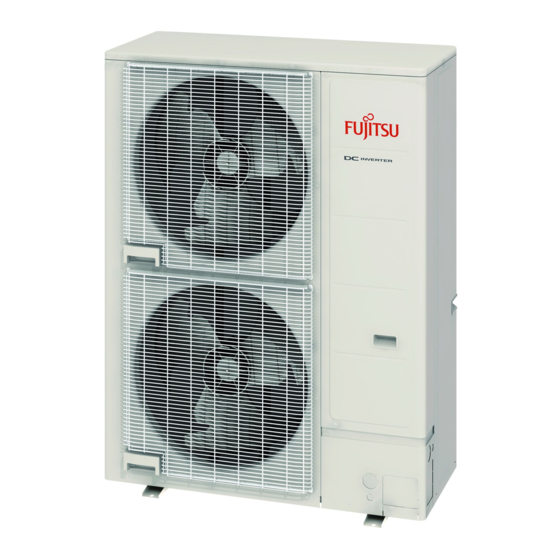
Fujitsu WOYK150LJL Installation Manual
Air to water heat pump outdoor unit
Hide thumbs
Also See for WOYK150LJL:
- Installation manual (84 pages) ,
- Design & technical manual (121 pages) ,
- Maintenance document (140 pages)
Table of Contents

Summary of Contents for Fujitsu WOYK150LJL
- Page 1 AIR TO WATER HEAT PUMP INSTALLATION MANUAL OUTDOOR UNIT (3 phase type) For authorized service personnel only. MANUEL D’INSTALLATION UNITÉ EXTÉRIEUR (Type 3 phases) Pour le personnel de service agrée uniquement. PART No. 9380545255...
-
Page 2: Table Of Contents
INSTALLATION MANUAL To avoid getting an electric shock, never touch the electrical components soon after the OUTDOOR UNIT [Original instructions] power supply has been turned off. After turning off the power, always wait 10 minutes or PART No. 9380545255 English more before you touch the electrical components. -
Page 3: About The Unit
2. ABOUT THE UNIT 2.3. Accessories WARNING 2.1. Precautions for using R410A refrigerant For installation purposes, be sure to use the parts supplied by the manufacturer or other prescribed parts. The use of non-prescribed parts can cause serious accidents WARNING such as the unit falling, water leakage, electric shock, or fi... -
Page 4: Drain Installation
CAUTION Unit: mm Do not install the outdoor unit in the following areas: • Area with high salt content, such as at the seaside. It will deteriorate metal parts, causing the parts to fail or the unit to leak water. •... -
Page 5: Transporting The Unit
When an obstruction is present also in the upward area (Unit : mm) 3.4. Transporting the unit (2) Obstacles at rear, sides, and above (1) Obstacles at rear and above WARNING Do not touch the fi ns. Otherwise, personal injury could result. Max. -
Page 6: Pipe Selection
• Do not install directly on the ground, this may result in equipment failure. 5. PIPE INSTALLATION-1 • The drain water is discharged from the bottom of the equipment. Construct a drain ditch around the base and discharge the drain water properly •... -
Page 7: Flare Connection
5.4.2. Pipe connection CAUTION For brazing material, use phosphor copper that does not require fl ux. Do not use fl ux to CAUTION braze pipes. If the fl ux is the chlorine type, it will cause the pipes to corrode. Be sure to install the pipe against the port on the indoor unit and the outdoor unit Furthermore, if the fl... -
Page 8: Connection System
5.4.3. Handling precautions for the valves CAUTION • Mounted part of Blank cap is sealed for protection. Do not block the walls and the ceiling until the sealing test and the charging of the • Fasten blank cap tightly after opening valves. refrigerant gas have been completed. -
Page 9: Electrical Wiring
6.2. Notes for electrical wiring CAUTION Check if the steel cylinder has a siphon installed or not before fi lling. (There is an indi- WARNING cation “with siphon for fi lling liquid” on the steel cylinder.) Wiring connections must be performed by a qualified person in accordance with speci- fications. -
Page 10: Knock Out Holes For Wiring
(3) Use the specifi ed wires, connect them securely, and fasten them so that there is no 6.4.2. Connection cable preparation stress placed on the terminals. • Keep the earth wire longer than the other wires. (4) Use an appropriate screwdriver to tighten the terminal screws. Do not use a screwdriver that is too small, otherwise, the screw heads may be damaged and 30 mm prevent the screws from being properly tightened. -
Page 11: Pipe Installation-2
• The printed characters for the LED display are shown below. 7. PIPE INSTALLATION-2 7.1. Installing insulation LED display part • Use an insulation on the refrigerant pipes to prevent burn injury, condensation and dripping. 7.2. Filling with putty Button part WARNING Fig. - Page 12 Table. Settings List LED display PUMP Factory Setting Item LOW NOISE PEAK CUT Content POWER/ DOWN setting ERROR MODE (L1) (L2) (L3) (L4) (L5) (L6) By using the “Low noise mode”, the limit of the noise level will be set to decrease the noise ○...
-
Page 13: External Input And Output
(6) Press [ENTER] button (SW109) and fi x it. (4) Press [ENTER] button (SW109). PEAK CUT PUMP DOWN LOW NOISE (L4) (L5) (L6) (L1) (L2) (L3) ○ ○ ● Level 1 100% of rated input ratio ○ ○ Defrost determina- ●... -
Page 14: External Output
• The switch can be used on the following condition: DC 12 V to 24 V, 1 mA to 15 mA. An air conditioner error status signal is produced when a malfunction occurs. Circuit diagram example Error status Error Connected unit Outdoor unit control (Locally purchased) PC board... -
Page 15: Error Code Check Table
12.2. Error code check table 13. PUMP DOWN Number of Error type WARNING blinks (LED) Never touch electrical components such as the terminal blocks except the button on Serial forward transfer error the display board. It may cause a serious accident such as electric shock. Discharge thermistor error During the pump-down operation, make sure that the compressor is turned off before Pressure sensor error... - Page 16 (5) When LED display changes as shown in the below fi gure, close the 3-way valve on the gas pipe side tightly. PUMP PEAK POWER/ ERROR DOWN NOISE MODE (L1) (L2) (L3) (L4) (L5) (L6) ● ○ ● ○ ○ ○...


Need help?
Do you have a question about the WOYK150LJL and is the answer not in the manual?
Questions and answers