Advertisement
Quick Links
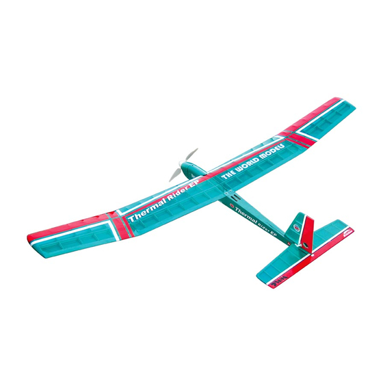
Thermal Rider EP
Thermal Rider EP
Wing Span
Wing Area
Flying Weight
Fuselage Length
Warning! This model is not a toy.
It is designed for maximum performance. Please seek advice if one is not familiar with this kind
of electric powered precision model. Operating this model without prior preparation may cause
injuries.Remember, safety is the most important thing. Always keep this instruction manual at
hand for quick reference.
The World Models
Manufacturing Co., Ltd.
www .thew orldm odels .com
A201PO25591104
Speed 400 motor
Specifications
*Specifications are subject to change without notice.*
INSTRUCTION MANUAL
78 in /
1980
mm
665 sq in / 42. 9sq dm
32 oz / 900 g
40 in / 1020mm
ALMOST-READY-TO-FLY (ARF) SERIES
FACTORY PRE-FABRICATED
MADE IN CHINA
Advertisement

Related Manuals for THE WORLD MODELS Thermal Rider EP


Summary of Contents for THE WORLD MODELS Thermal Rider EP
- Page 1 INSTRUCTION MANUAL Thermal Rider EP Thermal Rider EP Speed 400 motor Specifications 78 in / 1980 Wing Span 665 sq in / 42. 9sq dm Wing Area 32 oz / 900 g Flying Weight 40 in / 1020mm Fuselage Length *Specifications are subject to change without notice.*...
-
Page 2: Before You Begin
Thermal Rider EP Thermal Rider EP I N D E X BEFORE YOU BEGIN PARTS LIST ASSEMBLY P.3-9 SAFETY PRECAUTIONS BEFORE YOU BEGIN Read through the manual before you begin, so you will have an overall idea of what to do. - Page 3 Parts list 1. MAIN WING--1 set 7 SPONGE 10x50x150mm--2 pcs WING JOINER Ø6x226mm--1 pc. DOUBLE-SIDED TAPE(30x35mm)--1 pc. BATTERY TIE--1 pc. 2. STABILIZER & ELEVATOR--1 set STRAPER--2 pcs 3. VERTICAL FIN & RUDDER--1 set FUEL TUBE d2xD4x4mm--2 pcs 4. PUSHROD Ø1.4x618mm w / Threads(For Elevator)--1 pc. 8.
- Page 4 Main Wing Wing joiner Ø6x 226mm Completed Stabilizer & Elevator Apply instant type CA glue to both sides of each hinge. Bottom View Temporary install the main wing, adjust (Stabilizer) leveling of the stabilizer to make it as parallel to the main wing as possible. (Main Wing) A A' *Also refer to step 10 Wing Setting...
- Page 5 Vertical Fin & Rudder Apply instant type CA glue to both sides of each hinge. Peel off shaded Portion covering film. Completed A201PO25591104...
-
Page 6: Elevator Pushrod
Elevator Pushrod Screw PB2x10mm PB2x10mm Clevis Fuel Tube d2xD4x4mm Pushrod Horn 1.4x618mm TWM PL8210010 CLEVIS WRENCH Rudder Pushrod Screw PB2x10mm TWM PL8210010 CLEVIS WRENCH Pushrod Ø1.4 x 563mm Horn Clevis Pushrod Ø 1.4x563mm Fuel Tube PB2x10mm d2xD4x4mm A201PO25591104... - Page 7 Motor / Cowling Setting KP0011310 Solder Solder Optional Parts PM3x6mm Screw PM3x6mm PM2x12mm Screw PWA2x8mm Screw Outrunner Motor 28/ 30 d3xD7mm Washer KM0283010 d3xD7mm Washer Don't over-tighten the PM3 screws, too much Propeller Adaptor stress on the screws (d3xD5) HW2340100 could split the firewall.
-
Page 8: Radio Equipment
Radio Equipment Install and arrange the servo as shown in the diagram. Battery Elevator Servo Straper Elevator Pushrod Battery Tie Double-Side Tape Front Fuel Tube Ø4 x 4mm Speed 400 Motor Receiver Sponge Rudder Servo Rudder Pushrod Brushless ESC Main Wing Screw PM2.5 x 16mm Washer... - Page 9 Wing Setting A=A' B=B' C=C' Control Throws Rudder 30mm 30mm Elevator 15mm 15mm A201PO25591104...
- Page 10 400 motor. Thermal Rider EP Thermal Rider EP #Make sure the air field is spacious, never fly the plane too close to people and never get too close to a running propeller.
- Page 11 Pl8210010 Large Clevis Small Clevis A201PO25591104...
- Page 12 The World Models Manufacturing Co www .thew orldm odels .com A201PO25591104...
Need help?
Do you have a question about the Thermal Rider EP and is the answer not in the manual?
Questions and answers