Table of Contents
Advertisement
Quick Links
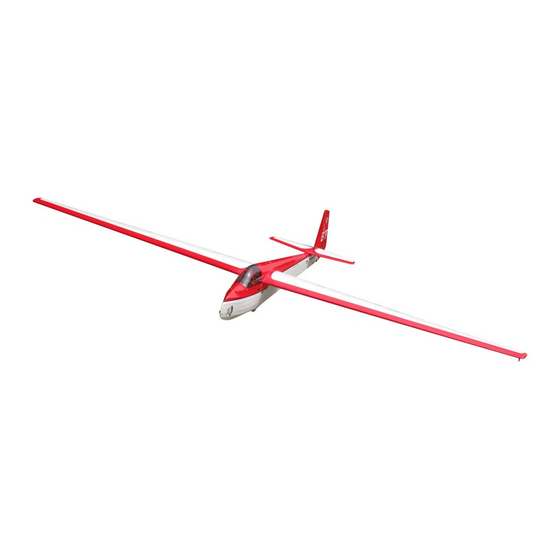
1/4 SCALE HALL CHEROKEE II
1/4 SCALE HALL CHEROKEE II
Requires: 5-channel radio w/ 7 Standard servos.
Wing Span
Wing Area
Flying Weight
Fuselage Length
Warning! This model is not a toy.
It is designed for maximum performance. Please seek advice if one is not familiar with this kind
of engine powered precision model. Operating this model without prior preparation may cause
injuries. Remember, safety is the most important thing. Always keep this instruction manual at
hand for quick reference.
The World Models
Manufacturing Co., Ltd.
www.theworldmodels.com
G336PO29441308
Specifications
130.7 in / 3320 mm
1190 sq in / 76.8 sq dm
8.33 Ib / 3780 g
64.5 in / 1637 mm
*Specifications are subject to change without notice.*
INSTRUCTION MANUAL
FACTORY PRE-FABRICATED
ALMOST-READY-TO-FLY(ARF)SERIES
MADE IN CHINA
( G336 )
Advertisement
Table of Contents

Related Manuals for THE WORLD MODELS Hall Cherokee II


Summary of Contents for THE WORLD MODELS Hall Cherokee II
- Page 1 INSTRUCTION MANUAL 1/4 SCALE HALL CHEROKEE II 1/4 SCALE HALL CHEROKEE II ( G336 ) Requires: 5-channel radio w/ 7 Standard servos. Specifications Wing Span 130.7 in / 3320 mm Wing Area 1190 sq in / 76.8 sq dm Flying Weight 8.33 Ib / 3780 g...
-
Page 2: Before You Begin
1/4 SCALE HALL CHEROKEE II 1/4 SCALE HALL CHEROKEE II INDEX BEFORE YOU BEGIN PARTS LIST ASSEMBLY P.3-P.9 SAFETY PRECAUTIONS BEFORE YOU BEGIN Read through the manual before you begin, so you will have an overall idea of what to do. -
Page 3: Parts List
Parts List 1. MAIN WING -- 1 pair 7. TAIL LANDING GEAR -- 1 pc. SCREW PA2.5x12mm -- 2 pcs 2. PUSHROD Ø1.8x60mm w/ Threads (For Aileron) -- 2 pcs LANDING WIRE STRAPS PL4114030 -- 1 pc. PUSHROD Ø1.8x50mm (For Spoiler) -- 2 pcs SCREW PB2x22mm -- 4 pcs 8. - Page 4 Main Wing Apply instant type CA glue to both sides of each hinge. Ailer on Ser v o & Spoiler Servo Lead Bottom View Aileron & Spoiler Servos Ø1mm pilot holes for World Models horn are pre-drilled. Please look for pin-hole PB2x22mm Screw marks at under side of control surfaces.
-
Page 5: Stabilizer & Elevator
Stabilizer & Elevator PM3x40mm Screw d3.2xD12mm Washer (Stabi l i zer) (Mai n Wi ng) A=A' B=B' Temporary install the main wing, adjust leveling of the stabilizer to make it as parallel to the main wing as possible. PM3x40mm Washer d3.2xD12mm Completed Vertical Fin &... -
Page 6: Rudder Pushrod
Rudder Pushrod Ø1m m pilot holes for Wor ld Models hor n ar e pr e-dr illed. Please look for pin-hole m ar ks at side of contr ol sur faces. PB2x30mm Screw PWA2x8mm Screw TWM PL8210010 CLEVIS WRENCH Fuel Tube D6x5mm Clevis PWA2x8mm... -
Page 7: Radio Equipment
Wheel 4.1mm Collar M4x60mm Socket Head Screw Nylon Insert Lock Nut 4.1mm Plastic Collar 4.1mm Collar Set Screw Wheel Ø76mm 4.1mm Plastic Collar Nylon Insert Lock Nut M4x60 mm Bottom View Radio Equipment Cable Tie 4x200mm Front Iron Aerotow Release Pushrod Ø2x267mm Straper... -
Page 8: Main Wings
Main Wings Wing Tube D22x989mm Lead to Ailer on Ser v o & Spoiler Servo Tape Completed Canopy & Scratch Guard ( Optional ) Silicon Grommet PWA2.3x8mm Screw PWA2.3x8mm d1.5xD6.5mm M3x10mm Socket Head Screw Scratch Guard d3.5xD8mm Fuselage Washer (Optional) d1.5xD6.5mm Silicon Grommet d1.5x6.5mm PWA2.3x8mm... - Page 9 Wing Seting Adjust the wing and fuselage configuration as shown in the diagrams. A=A' B=B' C=C' G336PO29441308...
-
Page 10: Control Throws
Control Throws Adjust the control throws as shown in the diagram. These throws are good for general flying. You can adjust according to your personal preference. Elevator 38mm 38mm Rudder 80mm 80mm Ailerons 20mm 20mm C.G. The ideal C.G. position is 116mm ( 4.57 in. ) behind the leading edge measured at where the wing meets the fuselage. - Page 11 LINKAGE CONNECTOR HW7111050 & HW7111060 Drill 2mm hole at servo horn. Insert linkage connector into servo horn. Make sure shoulder of screw is cleared from servo horn. Add washer to reduce play if necessary. Shoulder Tighten up the round nut against the shoulder.
- Page 12 1/4 Scale Hall Cherokee II Wing Bag...
-
Page 13: Optional Parts ( Accessories)
Optional Parts ACCESSORIES) Clevis Wrench 180mm Extension Code No. Size Package Code No. Size Package PL8210010 1 set KW0011800 180mm 1 set Large Clevis Small Clevis Special tool for clevis installation. Suitable for standard and small (EP) clevis. 180mm Y-Cord Code No. - Page 14 The World Models Manufacturing Co., Ltd. www.theworldmodels.com G336PO29441308...
Need help?
Do you have a question about the Hall Cherokee II and is the answer not in the manual?
Questions and answers