Table of Contents
Advertisement
Quick Links
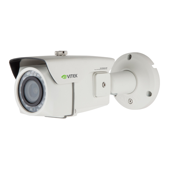
Virtuoso Series
Virtuoso Series 3.15 MegaPixel
Network Cameras
OPERATION MANUAL
FEATURES:
• Sony® 1/2.8" Progressive Scan CMOS Sensor
• Up to 30fps live view @ 2048 x 1536 (3.15 MegaPixel)
• MegaPixel IR Corrected Fixed, Varifocal, and Motorized Zoom Lens Options
• Optional Infrared LEDs enable viewing in total darkness up to 150 feet
• XD-DNR (2D-DNR + 3D-DNR) Noise Reduction
• True Day/Night by ICR - Dual Filter Switch
• Triple Streaming (H.264/MJPEG) offering Extensive Integration Possibilities
• Real-time Lens Distortion Correction (LDC) for an optically correct picture
• Compliance with the latest Onvif Profile S
• On-board network security with IP address filtering
• Advanced OSD Features including Image Stabilization & Corridor Mode
• MicroSD memory card slot for Local recording supporting up to 128GB
MicroSDXC cards
• Low Voltage & PoE (Power over Ethernet) Operation
Advertisement
Table of Contents

Related Manuals for Vitek Virtuoso Series


Summary of Contents for Vitek Virtuoso Series
-
Page 1: Network Cameras
Virtuoso Series Virtuoso Series 3.15 MegaPixel Network Cameras OPERATION MANUAL FEATURES: • Sony® 1/2.8” Progressive Scan CMOS Sensor • Up to 30fps live view @ 2048 x 1536 (3.15 MegaPixel) • MegaPixel IR Corrected Fixed, Varifocal, and Motorized Zoom Lens Options •... -
Page 2: Table Of Contents
Table of Contents OVERVIEW ..........................2 1.1. System Requirements ................... 2 1.2. Accessing the IP camera ..................2 LIVE ............................3 Quick Setup ..........................4 3.1. Information ......................4 3.2. Users ........................4 3.3. Network ........................ 6 3.4. Date & Time ......................6 Video ............................ -
Page 3: Overview
8.1. Upgrading the Firmware ..................35 1. OVERVIEW This camera is a Full-HD network camera with a built-in web based This camera supports dual compression formats and triple streaming simultaneously. The two standard compression formats include, H.264 and MJPEG. The triple streams can be configured to a variety of resolutions, bit rates and frame rates. -
Page 4: Live
2. LIVE 1. Enter live View mode 2. Enter Playback (from SD card) 3. Enter Setup Mode 4. Logout of camera 5. Pause live view 6. Return to live view after pausing 7. Save Snapshot to computer 8. Zoom on live view 9. -
Page 5: Quick Setup
12. Record to Micro SD card 13. Information (system info) 14. Stream: choose which stream is live view 1, 2, or 3 15. Screen Ratio: choose either 16:9 or 4:3 16. Event Action: Manually start Event according to Event settings 17. - Page 6 Users-Add To add a new user: 1. Click the Add tab, and then a new pop-up window appears. 2. Add user Name and Password 3. Select Group for this user 4. Click the OK button to save the settings. Users-Edit page NOTE The user name can’t be modified.
-
Page 7: Network
3.3. Network IP Address: Obtain IP address via DHCP: Select this if you want to assign the IP address from DHCP server/router automatically, and then the remaining settings are read-only text. Use the following IP address: Select this if you want to assign the IP address manually. IP address: The address of the camera connected to the network. -
Page 8: Video
Time Format: The default setting is 24 hours. 4. Video Video Source: Specify the system performance. Depending on video source mode, each stream configuration will be affected and the streaming will be adjusted under system performance automatically. Mode: The default mode is 1920x1080@30fps (NTSC) or 25fps (PAL) at 2MP mode, and 2048x1536@30fps (NTSC) or 25fps (PAL) at 3MP mode. -
Page 9: Image-Basic
Video Stream2: Configures the MJPEG or H.264 setting value for stream2. Compression: The default setting is MJPEG. Resolution: Specified as the number of pixel-columns (width) by the number of pixel-rows (height). The Resolution can be adjusted in the range from 320x240 to 640x480. Video Stream3: Configures the H.264 setting value for stream3. -
Page 10: Exposure Control
Enable flip image: Rotate the camera image 180 degrees vertically. Enable mirror image: Rotate the camera image 180 degrees horizontally. Image-OSD Enable text OSD: Enter camera name and check box to display Enable date & time OSD: Check box to display Date & Time Enable zoom &... - Page 11 noise. low light situations but will increase the amount of image The gain can be adjusted in the range 1.2~54 dB Auto Iris: When auto iris lens is used set to ON Auto Flicker-less: when turned on it helps eliminate flicker do to florescent lighting Image-AWB White Balance Control: White balance control is used to make colors in the image appear...
-
Page 12: Image-Wdr
Image-Day/Night Mode: Configure one of Automatic, Day, Night or External mode to transit the IR cut filter. The default setting is External for IR cameras and Automatic for non IR cameras. Switching Time: Configure the switching time(1~60sec) of the IR cut filter transition delay 4.2. -
Page 13: Image-Blc
4.3. Image-BLC BLC Control Mode: On/Off Level: HLC Control Mode: On/Off, Blacks out extreme bright light form the scene Image-DNR 2D-NR / 3D-NR Control: Mode: On/Off Level: 1~4, the higher the level the less noise but image may not look as sharp (hazy) Image-Corridor... - Page 14 Corridor Control: The corridor format allows you to get a vertically oriented video stream from the camera. The video is adapted perfectly to the monitored area, maximizing image quality while eliminating bandwidth and storage waste. The Corridor Format is even more useful for modern HDTV network cameras that deliver a 16:9 aspect ratio since the resulting image will have a 9:16 aspect ratio –...
-
Page 15: Digital Zoom
Privacy Mask Privacy Mask: To set the privacy mask 1. Check the Enable privacy mask check box. 2. Right click mouse button on the screen and then specify the area. 3. Enter the name and then click Save. 4. If you want to delete a masked area in the list, click the icon 4.4. -
Page 16: Events
To permanently have the Digital Zoom on, check “Enable digital zoom” then choose from the dropdown box the zoom ratio and click Save 5. Events 5.1. Motion Detection Motion Detection: Motion detection is used to generate an alarm whenever movement occurs (or stops) in the viewer. -
Page 17: Trigger-Alarm In (Future Use)
5.2. Trigger-Alarm In (future use) Alarm In: Click the Enable alarm in checkbox to enable the Alarm In port. Type: The default setting is NO. • Normally Open • Normally Close Dwell time: The default setting is 3 seconds. NOTE Dwell Time is the duration of the input time before executing an event. -
Page 18: Manual Trigger
Manual Trigger: The Manual Trigger features an alarm out signaling, JPEG file transfer to FTP server, and sends email to SMTP server whenever operator clicks Manual Trigger button in the Live View window. NOTE Dwell Time is the duration of the input time before executing an event. Trigger-Network Network Loss: This is used to trigger an event... -
Page 19: Action-Alarm Out (Future Use)
5.3. Action-Alarm Out (future use) Alarm Out Port Setting: This page allows you to configure the alarm output supported by the camera. Port can be given as Normally Open or Normally Close state, and its Normal state can be configured. Type: The default setting is NO. - Page 20 Login method: Select one for SMTP authentication method allowed. NOTES - If a PLAIN or LOGIN mechanism is negotiated, the camera sends user name and password to the SMTP server. - The LOGIN mechanism is supported by Microsoft, as well as by some other clients. Most other clients support the PLAIN authentication mechanism.
- Page 21 • Passive Mode: Under normal circumstances the network camera simply requests the target FTP server to open the data connection. Checking this box issues a PASV command to the FTP server and establishes a passive FTP connection; whereby the network camera actively initiates both the FTP control and data connections to the target server.
- Page 22 camera will boost the streaming performance dependent on each video stream setting. Rule This page shows current configuration status when event is activated. The common event actions will upload images to a specified destination or send an email or active an output port Event Rule List: An event type is a set of parameters describing how the camera will...
-
Page 23: Tamper
Active output: Click the Active output port checkbox to enable the Alarm out port. E-mail: Click the Email checkbox to enable the emailing below each email address. • To email address: Click the each email addresses checkbox. FTP: Click the FTP checkbox to enable the image uploading to FTP server using JPEG image. Video Boost: Click the Video Boost checkbox to enable the video boost streaming. -
Page 24: System
6. System 6.1. Security-Users Users List: User accounts can be added or modified or removed. The authority depends upon user group automatically and shows the permission status to access the menus. The default user name / password are admin . Name: Shows the name which registered to access the camera. -
Page 25: Security-Https
Users-Edit To edit a user: 1. Select one of the User Name in the User List you want to modify. 2. Click the Edit tab, and then new pop-up window appears. 3. Click in the Password box and type a password (1 to 8 alphanumeric characters). •... -
Page 26: Security-Ip Filter
Connection mode: The default setting is HTTP&HTTPS. • HTTP: Sensitive data will be transfer without encryption during transmission. Supports a URL that only starts with "HTTP:" • HTTPS: HTTPS (Hypertext Transfer Protocol over SSL) is a protocol used to provide encrypted transmission. -
Page 27: Security-Onvif
To add a subnet of network addresses, these must be added in CIDR (Classless Inter-Domain Routing) notation. For example: entering 192.168.1.0/24 will add all the addresses in the range 192.168.1.1 to 192.168.1.254. Please contact your network administrator for more detail. •... -
Page 28: Network-Tcp/Ip
New Time: Select one of the server times. Synchronize with computer time: Sets the time according to the clock on your computer. Set manually: Using this option allows you to manually enter the date and time. Synchronize with NTP Server: This option will obtain the correct time from an NTP server every 1~24 hours. - Page 29 IP Address: Obtain IP address via DHCP server: Select the choice box if you want to assign the IP address from DHCP server automatically, and then the remaining setting are read-only text. Use the following IP address: Select the choice box if you want to assign the IP address manually.
-
Page 30: User Name
Network-DDNS The DDNS (Dynamic DNS) service can provide the camera with its own URL (web address), which can then be used to access it over the Internet. Use the DDNS service to assign a host name for easy access to your network camera. NOTES •... -
Page 31: Network-Rtp
6.7. Network-RTP Port Range: The RTP Port range defines the range of ports from which the video/audio ports are automatically selected. This feature is useful if the camera is connected to a NAT router with manually configured port mapping. NOTE Limit the range of ports permitted for RTP unicast/multicast by entering the Start port and End port in the provided fields. - Page 32 NOTE The RTP port entered here must be even values. TTL: The TTL can be entered in the range 1-255. The default setting is 1. NOTES • TTL (Time To Live) If IP packets (i.e. data) fail to be delivered to their destination within a reasonable length of time (which could be for various reasons), this setting tells network routers when to discard the packet.
- Page 33 Zero configuration networking allows devices such as computers and printers to connect to a network automatically. Without zeroconf, a network administrator must set up services, such as Dynamic Host Configuration Protocol(DHCP) and Domain Name System(DNS), or configure each computer’s network settings manually, which may be difficult and time-consuming. Zeroconf: The default setting is enabling.
- Page 34 Reset: The unit is restarted and most current settings are reset to factory default values, but the following settings does not reset. • The boot protocol (DHCP or static) • The static IP address • The default router • The subnet mask •...
-
Page 35: Audio (Vtc-Ir403 Only)
Log & Report: The log files records event in the unit since the last system restart and can be a useful diagnostic tool when troubleshooting. The Report contains important information about the system. System Log: Provides the system log information. Event Log: Provides the events log information. -
Page 36: Audio Input
[ NOTE ] G.711, also known as Pulse Code Modulation (PCM), is a very commonly used waveform • codec. G.711 uses a sampling rate of 8,000 samples per second. Non-uniform quantization (logarithmic) with 8 bits is used to represent each sample, •... - Page 38 Version 2.0 28492 CONSTELLATION ROAD VALENCIA, CA 91355 May 2016 WWW.VITEKCCTV.COM...
Need help?
Do you have a question about the Virtuoso Series and is the answer not in the manual?
Questions and answers