Table of Contents
Advertisement
Quick Links
I n s t r u c t i o n M a n u a l
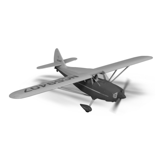
.46-.55 SCALE 1:8 ARF
SPECIFICATION
- Wingspan: 1604mm (63.31in)
- Length: 1224mm (48. 1 in)
- Flying weight: 2.6-3.0 kg
- Wing area: 37.5 dm2
- Wing loading: 74.5g/dm2
- Wing type: Naca airfoils
- Covering type: Genuine ORACOVER®
- Gear type: Aluminum main gear and
spring tail gear (included)
- Spinner size: Plastic 58mm (included)
- Radio: 4 channel minimum (not included)
- Servo: 2 aileron; 1 elevator; 1 rudder;
1 throttle (not included)
- Recommended receiver battery:
4.8-6V / 800-1200mAh NiMH (not included)
- Propeller: suit with your engine
- Engine: .46-.55 / 2-stroke or .52/4-stroke
glow engine (not included)
- Motor: brushless outrunner 1000-1400 W,
480 KV (not included)
- Gravity CG: 65 mm (2.6 in) Back from
the leading edge of the wing, at the fuselage
- Control throw Ailerons: Low: 10mm up/down,
10% expo; High: 12mm up/down, 10% expo
- Control throw Elevators: Low: 8mm up/down,
12% expo; High: 10mm up/down, 12% expo
- Control throw Rudder: Low: 25mm right/left,
15% expo; High: 40mm right/left, 15% expo
- Experience level: Intermediate
- Plane type: Scale Civilian
RECOMMENDED MOTOR AND BATTERY SET UP
- Motor: RIMFIRE .46-.55 (not included)
- Lipo cell: 6 cells / 4000 – 5500mAh (not included)
- Esc: 50-70A (not included)
Advertisement
Table of Contents

Subscribe to Our Youtube Channel
Related Manuals for Phoenix Model stinson .46-.55 SCALE 1:8 ARF


Summary of Contents for Phoenix Model stinson .46-.55 SCALE 1:8 ARF
- Page 1 I n s t r u c t i o n M a n u a l .46-.55 SCALE 1:8 ARF SPECIFICATION - Engine: .46-.55 / 2-stroke or .52/4-stroke - Wingspan: 1604mm (63.31in) glow engine (not included) - Length: 1224mm (48. 1 in) - Motor: brushless outrunner 1000-1400 W, 480 KV (not included) - Flying weight: 2.6-3.0 kg...
-
Page 3: Safety Precaution
This will assure proper assembly. The TEMPORARY PIN STINSON .46-.55 SCALE 1:8 ARF is hand made TO KEEP HINGE from natural materials, every plane is unique and CENTERED minor adjustments may have to be made. -
Page 4: Installing The Aileron Servos
Instruction Manual STINSON INSTALLING THE AILERON SERVOS 5. Place the aileron servo tray / hatch into the servo box on the bottom of the wing and drill 1,6mm pilot holes through the tray and the servo box for each of the four mounting screws. 1. -
Page 5: Installing The Aileron Linkages
Instruction Manual STINSON To the cowl RIGHT WRONG Silicone Tube 3. Repeat step # 1 - # 2 to install the control horn on the opposite aileron. INSTALLING THE AILERON LINKAGES 9. Repeat step # 4 - # 8 to install the second aileron linkage. - Page 6 Instruction Manual STINSON Screw 7. Test the position of the elevator and adjust it as 4. With the horizontal stabilizer correctly aligned, shown. mark the shape of the fuselage onto the bottom and into the top of the horizontal stabilizer using a water soluble/ non-permanent felt-tip pen.
-
Page 7: Installing The Tail Wheel
Instruction Manual STINSON 9. After the epoxy has fully cured, remove the masking tape or T-pins used to hold the stabilizer in place and carefully inspect the glue Glue the hinges joints. Use more epoxy to fill in any gaps that by C.A glue were not filled previously and clean up the excess using a paper towel and rubbing alcohol. -
Page 8: Installing The Main Landing Gear
Instruction Manual STINSON Screw MAIN GEAR INSTALLATION INSTALLING THE WHEEL PANTS 1. Locate the wheel pants from the hardware bag. Mark the locations of the mounting axles onto the wheel pants. The locations of the two mounting holes are the middle of the wheel opening, on right side, left side and 10mm from the bottom of the wheel pant. -
Page 9: Engine Installation
Instruction Manual STINSON Installing the OS 55 AX Secure Screw the plastic cover ENGINE INSTALLATION INSTALLING THE THROTTLE PUSHROD HOUSING 1. Install the engine mount into the fire wall using 4mm x 25mm screw. 110mm 2. Place the engine into the engine mount and align it properly with the front of the cowling. - Page 10 Instruction Manual STINSON FUEL TANK INSTALLING THE STOPPER ASSEMBLY 1. The stopper has been pre-assembled at the factory. 2. Using a modeling knife, cut one length of silicon fuel line (the length of silicon fuel line is calculated by how the weighted clunk should rest about 8mm away from the rear of the tank and move freely inside the tank).
-
Page 11: Installing The Elevator Pushrod
Instruction Manual STINSON INSTALLING THE ELEVATOR PUSHROD Blow through one of the lines to ensure the fuel lines have not become kinked inside the fuel tank compartment. Air should flow through easily. 1. Locate the pushrod exit slot on the right side and left side of the fuselage. -
Page 12: Installing The Rudder Pushrod
Instruction Manual STINSON 10. Be sure both elevator halves are flat. Center 4. Install the clevis on the rudder pushrod. Make both elevator halves and hold them in place sure 6mm of thread shows inside the clevis. using a couple of pieces of masking tape. 5. -
Page 13: Mounting The Cowl
Instruction Manual STINSON MOUNTING THE COWL 1. Remove the muffler and needle valve assembly from the engine. Slide the fiberglass cowl over the engine. 2. Measure and mark the locations to be cut out for engine head clearance, needle valve, muffler. -
Page 14: Installing The Wing Strut
Instruction Manual STINSON INSTALLING THE WING STRUT The wing strut was installed as the picture below. Cowl area cutout for proper airflow to carburetor. FINAL ASSEMBLY INSTALLING THE SPINNER Install the spinner back-plate, propeller and spinner cone. The spinner cone is held in place using two 3mm x 15mm wood screws. -
Page 15: Installing The Door
Instruction Manual STINSON Screw Screw INSTALLING THE DOOR INSTALLING THE PILOT 1. That is the final working. Attach the door to the Do not glue the pilot to the block of wood fuselage by two CA hinge and glue the hinge because the pilot must be remove when by C.A glue. -
Page 16: Lateral Balance
Instruction Manual STINSON 2. Mount the wing to the fuselage. Using a couple Elevator Aileron Rudder of pieces of masking tape, place them on the top side of the wing 65mm back from the 10mm 25mm leading edge, at the fuselage sides. 10mm 12mm 40mm... - Page 17 I/C FLIGHT WARNINGS Always operate in open areas, away Keep all onlookers (especially small from factories, hospitals, schools, THE PROPELLER IS DANGEROUS children and animals) well back from buildings and houses etc. NEVER fly Keep fingers, clothing (ties, shirt the area of operation. This is a flying your aircraft close to people or built sleeves, scarves) or any other loose aircraft, which will cause serious...
- Page 18 I/C FLIGHT GUIDELINES Operate the control sticks on the When ready to fly, first extend the transmitter and check that the control transmitter aerial. surfaces move freely and in the ALWAYS land the model INTO the CORRECT directions. wind, this ensures that the model lands at the slowest possible speed.
Need help?
Do you have a question about the stinson .46-.55 SCALE 1:8 ARF and is the answer not in the manual?
Questions and answers