Phoenix Model Yak 54 Instruction Manual
Hide thumbs
Also See for Yak 54:
- Instruction manual (16 pages) ,
- Instruction manual (12 pages) ,
- Instruction manual (17 pages)

Related Manuals for Phoenix Model Yak 54


Summary of Contents for Phoenix Model Yak 54
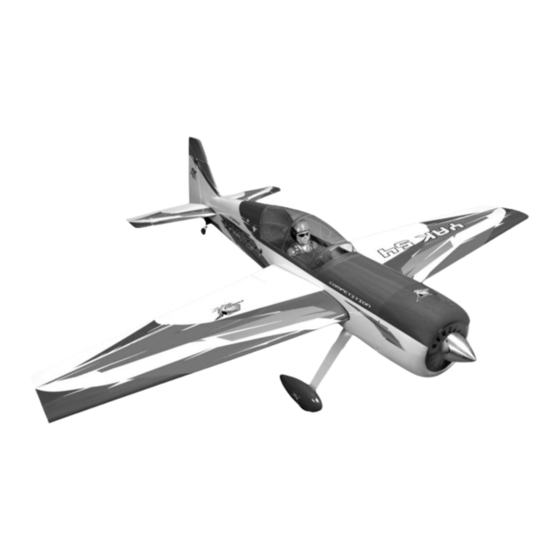
- Page 1 I n s t r u c t i o n M a n u a l Wingspan : mm (65.83 inches) 1672 Length mm (63.8 inches) 1620 Weight : 4500gr - 5000gr Engine : 120 two stroke Radio : 6 channel/ 5 high torque servo standard servo...
-
Page 3: Kit Contents
Instruction Manual YAK 54 KIT CONTENTS: We have organized the parts as they come out of the box for better identification during assembly. We recommend that you regroup the parts in the same manner. This will ensure you have all of parts required before you begin assembly. -
Page 4: Tools And Supplies Needed
1. Please trial fit all the parts. Make sure you have the correct parts and that they fit and are aligned properly before gluing! This will assure proper assembly. The YAK 54 ARF is hand made from INSTALLING THE AILERONS natural materials, every plane is unique and minor adjustments may have to be made. -
Page 5: Installing The Control Horns
Instruction Manual YAK 54 INSTALL THE AILERONS SERVOS & PUSHRODS 1. Install the servo in the wing require the use of one 305mm servo extension for each aileron servo. One Y-harness connector is required and is used to allow the aileron servo to plug into one slot in your receiver. -
Page 6: Installing The Aileron Linkages
Instruction Manual YAK 54 2. Secure the control horn into the aileron. 1. Locate the pushrod wire. Slide a silicon clevis retainer onto a clevis. Screw a M3 nut and a threaded metal clevis onto the threaded end of the wire. Tighten the nut against the clevis and... -
Page 7: Installing The Horizontal Stabilizer
Instruction Manual YAK 54 2. Remove the covering from the stabilizer. When cutting through the covering to remove it, cut with only enough pressure to only cut through the covering it's self. Cutting into the balsa structure may weaken it. This could lead to possible failure during flight. -
Page 8: Installing The Rudder
Instruction Manual YAK 54 INSTALLING THE RUDDER 5. When you are sure that everything is aligned correctly, mix up a generous amount of 30 minute epoxy. Apply a thin layer to the bottom Repeat step 1 - step 2 from the installing aileron and to the top of the stabilizer mounting area for the installing rudder. -
Page 9: Installing The Tail Wheel
Instruction Manual YAK 54 INSTALLING THE TAIL WHEEL 5. Connect the spring. 1. The tail wheel set. INSTALLING THE MAIN LANDING GEAR 1. Nuts have been installed at the factory. 2. Remove the covering. 2. Install main landing gear into the fuselage using (4) 4mm x 20mm socket head screws and flat washers provided in the kit. - Page 10 Instruction Manual YAK 54 Installing the engine Install with OS 22cc Engine Collar Collar 4mm collar 150mm 4mm axle 8mm screw After installing the wheel pant, apply a small drop of thin C/A to the bottom nut. Install with OS 120 two stroke INSTALLING THE THROTTLE PUSHROD HOUSING 1.
-
Page 11: Installing The Stopper Assembly
Instruction Manual YAK 54 6. When satisfied with the alignment of the stopper assembly tighten the 3mm x 20mm machine screw until the rubber stopper expands and seals the tank opening. Do not over tighten the assembly as this could cause the tank to split. -
Page 12: Installing The Throttle Servo
Instruction Manual YAK 54 INSTALLING THE THROTTLE SERVO . Repeat these step as installing the aileron linkages (Page 4 and page 5). 1. Install the rubber grommets and brass collets into the elevator, rudder and throttle servos. Test fit the servos into the servo tray. Trim the tray if necessary to fit your servos 2. -
Page 13: Installing The Rudder Servo
Instruction Manual YAK 54 . Repeat these step for the second servo elevator. Control horn Control horn Screw 3. Install the control horn to the rudder. INSTALLING THE RUDDER SERVO Install the rudder servo to the fuselage as shown. Control horn Control horn 4. -
Page 14: Mounting The Cowl
Instruction Manual YAK 54 3. Slide the adjustable metal connector/ servo arm assembly over the plain end of the pushrod wire. Position the throttle stick and the throttle trim at their lowest positions. 4. Manually push the carburator barrel fully closed. -
Page 15: Final Assembly
Instruction Manual YAK 54 2. Cut out the switch hole using a modeling knife. CA glue Use a 2mm drill bit and drill out the two mounting holes through the fuselage side. 3. Secure the switch in place using the two machine screws provided with the radio system. - Page 16 Instruction Manual YAK 54 open and close the canopy Screw BALANCING 1. It is critical that your airplane be balanced INSTALLING and secure the wing correctly. Improper balance will cause your plane to lose control and crash. 1. Find the hole on the top of the wing by taking THE CENTER OF GRAVITY IS LOCATED measurements as picture below.
-
Page 17: Lateral Balance
LATERAL BALANCE 3-D PERFORMANCE SETTINGS After you have balanced a plane on the C.G. The YAK 54 ARF will perform 3-D aerobatics You should laterally balance it. Doing this will easily if you use the largest engines help the airplane track straighter. - Page 18 I/C FLIGHT WARNINGS Always operate in open areas, away Keep all onlookers (especially small from factories, hospitals, schools, THE PROPELLER IS DANGEROUS children and animals) well back from buildings and houses etc. NEVER fly Keep fingers, clothing (ties, shirt the area of operation. This is a flying your aircraft close to people or built sleeves, scarves) or any other loose aircraft, which will cause serious...
- Page 19 I/C FLIGHT GUIDELINES Operate the control sticks on the When ready to fly, first extend the transmitter and check that the control transmitter aerial. surfaces move freely and in the ALWAYS land the model INTO the CORRECT directions. wind, this ensures that the model lands at the slowest possible speed.
Need help?
Do you have a question about the Yak 54 and is the answer not in the manual?
Questions and answers