Olympus BX51 Instructions Manual
System
Hide thumbs
Also See for BX51:
- Instructions manual (40 pages) ,
- Operating manual (17 pages) ,
- Operating manual (11 pages)
Table of Contents
Advertisement
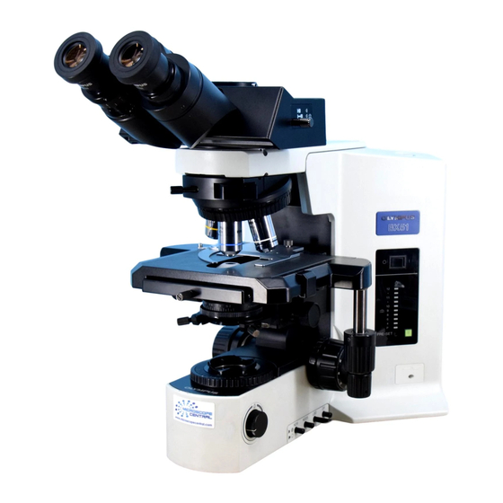
INSTRUCTIONS
BX51/BX52
SYSTEM MICROSCOPE
This instruction manual is for the Olympus System Microscopes Models BX51 and BX52. To ensure
the safety, obtain optimum performance and to familiarize yourself fully with the use of this micro-
scope, we recommend that you study this manual thoroughly before operating the microscope.
Retain this instruction manual in an easily accessible place near the work desk for future reference.
A X 9 8 5 5
Advertisement
Table of Contents


Need help?
Do you have a question about the BX51 and is the answer not in the manual?
Questions and answers