Table of Contents
Advertisement
INSTRUCTIONS
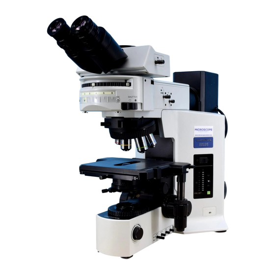
BX51M
SYSTEM METALLURGICAL
MICROSCOPE
This instruction manual is for the Olympus System Metallurgical Microscope Model BX51M. To
ensure the safety, obtain optimum performance and to familiarize yourself fully with the use of this
microscope, we recommend that you study this manual thoroughly before operating the micro-
scope. Retain this instruction manual in an easily accessible place near the work desk for future
reference.
A X 7 6 0 9
This publication is printed on 100% recycled paper
Advertisement
Table of Contents

Related Manuals for Olympus BX51M


Summary of Contents for Olympus BX51M
- Page 1 SYSTEM METALLURGICAL MICROSCOPE This instruction manual is for the Olympus System Metallurgical Microscope Model BX51M. To ensure the safety, obtain optimum performance and to familiarize yourself fully with the use of this microscope, we recommend that you study this manual thoroughly before operating the micro- scope.
- Page 2 NOTE: This equipment has been tested and found to comply with the limits for a Class A digital device, pursuant to Part 15 of the FCC Rules. These limits are designed to provide reasonable protection against harmful interference when the equipment is operated in a commercial environment. This equipment generates, uses, and can radiate radio frequency energy and, if not installed and used in accordance with the instruction manual, may cause harmful interference to radio communications.
-
Page 3: Table Of Contents
BX51M CONTENTS Correct assembly and adjustments are critical for the microscope to exhibit its full performance. If you are going to assemble the microscope yourself, please read chapter 8, “ASSEMBLY” (pages 27 to 29) carefully. IMPORTANT — Be sure to read this section for safe use of the equipment. —... -
Page 4: Main Switch
This microscope employs a UIS2 (UIS) (Universal Infinity System) optical design, and should be used only with UIS2 (UIS) eyepieces, objectives and condensers for the BX2 series. (Some of the modules de- signed for the BX series are also usable. For details, please consult Olympus or the latest catalogue.) SAFETY PRECAUTIONS 1. - Page 5 2. Do not use the microscope where it is subjected to direct sunlight, high temperature and humidity, dust or vibrations. (For the operating conditions, refer to chapter 6, “SPECIFICATIONS”.) 3. The BX51M can be used with an intermediate attachment such as a U-CA magnification changer or U-EPA2 eyepoint adjuster.
- Page 6 Caution If the microscope is used in a manner not specified by this manual, the safety of the user may be imperiled. In addition, the equipment may also be damaged. Always use the equipment as outlined in this instruction manual. The following symbols are used to set off text in this instruction manual.
- Page 7 BX51M NOMENCLATURE }If you have not yet assembled the microscope, read chapter 8, “ASSEMBLY” (pages 27 to 29). }This illustration shows the BX-51RF microscope frame with the BX-RLA2 reflected light brightfield/darkfield illuminator in- stalled on it. For the nomenclature of the BX-URS2 universal illuminator, please refer to its instruction manual.
- Page 8 REFLECTED LIGHT BRIGHTFIELD/DARKFIELD OBSERVATION PROCEDURE }The following flow shows the basic operating procedure for reflected light brightfield or darkfield observation. The operating procedures for polarized light and Nomarski DIC observations will be described separately in their descriptions. (Controls Used) (Page) Select the brightfield (BF) or darkfield (DF) ob- @ Mirror selector lever (P.
- Page 9 BX51M Insertion from the left š ™ Œ ‹ ‰ ² ³ † ƒ ‡ … Š ‡ } Make a photocopy of the observation procedure pages and post it near your microscope.
-
Page 10: Using The Controls
USING THE CONTROLS 3-1 Base Voltage Indication (Fig. 3) 1. Turn the brightness adjustment knob @ clockwise to increase the volt- age and make illumination brighter. 2. The numerals on the left of the lamp voltage LEDs ² indicate the ap- proximate voltage. -
Page 11: Focusing Block
BX51M 3-2 Focusing Block Adjusting the Focus (Fig. 5) The coarse adjustment knob @ and fine adjustment knob ² are de- signed to raise the stage (i.e. to let the specimen approach the objective) when they are rotated in the direction of the arrows. -
Page 12: Pre-Focusing Lever
Pre-focusing Lever (Fig. 8) }The pre-focusing lever ensures that the objective does not come in con- tact with the specimen and simplifies focusing. After focusing on the specimen with the coarse adjustment knob, turn this lever @ in the direction of the arrow and lock; the upper limit of coarse adjustment movement is set at the locked position. -
Page 13: Centering The Aperture Iris Diaphragm (As)
BX51M Centering the Field Iris Diaphragm (FS) (Fig. 10) 1. Slide the mirror selector lever @ to “BF”. ² 2. Engage the 10X objective by rotating the revolving nosepiece, place the specimen on the stage and adjust approximate focusing. 3. Pull out the FS knob ² on the reflected light illuminator to reduce the aperture iris diaphragm a little. -
Page 14: Using The Nd Filter Knob
Using the ND Filter Knob (Fig. 12) }The ND filter is interlocked with the brightfield (BF) light path switching so it can be engaged or disengaged according to the mirror selector lever @. The ND filter makes it possible to reduce the glare when darkfield (DF) ²... -
Page 15: Stage
BX51M 3-4 Stage Placing the Specimen }The maximum load capacities are as follows. · Stage: 1.5 kg · Stage plate: 500 g (U-SVRM/SVLM) 1 kg (U-SIC4R2/SIC4L2) # Do not place a specimen which is heavier than above. Otherwise, difficulty in stage movement or wear will result. -
Page 16: Adjusting The X/Y-Axis Knob Tension
Adjusting the X/Y-Axis Knob Tension (Fig. 17) ² }This mechanism is provided only with the U-SVRM/SVLM stage. 1. Hold the X-axis knob @ and slide up the Y-axis knob ² up to expose the adjustment knobs. 2. Turning the X-axis adjustment knob ³ or Y-axis adjustment knob | clock- ³... -
Page 17: Rotating The Stage
BX51M Rotating the Stage (Fig. 19) # The U-SIC4R2/SIC4L stage cannot be rotated. 1. Slightly loosen the stage clamping screw @ using the Allen screwdriver. 2. The stage can be rotated both clockwise and counterclockwise while holding the stage. # A click may be heard and felt during rotation. However, this is due to the construction of the substage and does not indicate a malfunc- tion. -
Page 18: Observation Tube
3-5 Observation Tube Adjusting the Interpupillar Distance (Fig. 21) While looking through the eyepieces, adjust for binocular vision until the left and right fields of view coincide completely. The index dot · indicates the interpupillary distance. }Note your interpupillary distance so that it can be quickly duplicated. Fig. -
Page 19: Using Eyepiece Micrometer Disks
BX51M Using Eyepiece Micrometer Disks (Fig. 25) Eyepiece micrometer disks can be inserted into the WHN10X-H (or WHN10X) eyepieces. However, if the eyepiece does not have the helicoid adjustment facility and your eyesight is poor, you may have difficulties in focusing on the eyepiece micrometer disk. -
Page 20: Observation Methods (Using Bx-Rla2)
OBSERVATION METHODS (Using BX-RLA2) }For the observation methods with the BX-URA2 universal illuminator, refer to its instruction manual. 4-1 Reflected Light Brightfield/Darkfield Observation See “REFLECTED LIGHT BRIGHTFIELD/DARKFIELD OBSERVATION PROCEDURE” on page 5. 4-2 Reflected Light Nomarski DIC (Differential Interference Contrast) Observation # The performance of polarizer may deteriorate when it has been exposed to light for a long period (about continu- ous 2000 hours). - Page 21 BX51M Setting the DIC Slider (Fig. 31) ² 1. Loosen the mounting knob @ on the front of the DIC revolving nose- piece, insert the DIC slider ² so that the surface with indication faces up, and clamp by tightening the mounting knob.
-
Page 22: Reflected Light Simplified Polarized Light Observation
U-DICRH 1. Adjust the background contrast by turning the prism movement knob | on the DIC slider as described below. (Fig. 31) 2. When the prism movement knob on the U-DICRH DIC slider is turned, the interference color in the background varies from -100 to 100 nm. Set the retardation which can provide best contrast. -
Page 23: Troubleshooting Guide
Under certain conditions, performance of the unit may be adversely affected by factors other than defects. If problems occur, please review the following list and take remedial action as needed. If you cannot solve the problem after checking the entire list, please contact your local Olympus representative for assistance. Problem... - Page 24 Problem Cause Remedy Page f ) cont’d Objective is not correctly engaged in light Make sure that revolving nosepiece – path clicks into place correctly. Dirt/dust on extremity of objective Clean it thoroughly. Dirt/dust on specimen Clean specimen. – g) One side of image is blurred. Revolving nosepiece is not installed cor- Secure it by pushing in the sliding –...
- Page 25 BX51M Problem Cause Remedy Page 4. Observation Tube a) Field of view of one eye does not Interpupillary distance is incorrect. Adjust interpupillary distance. match that of the other. Incorrect diopter adjustment. Adjust diopter. Different eyepieces are used on left and Change on eyepiece to match the right.
-
Page 26: Specifications
SPECIFICATIONS Item Specification Optical system UIS2 (UIS) (Universal Infinity System) optical system Reflected light illumination Reflected light illuminator (BX-RLA2), tube magnification 1X, super widefield (FN 26.5) compat- ible. Available observations: @Reflected light brightfield ²Reflected light darkfield ³Reflected light Nomarski DIC |Reflected light simplified polarized light Electrical system Rated input voltage: 100-120 V/220-240 V... -
Page 27: Optical Characteristics <
(as shown in the diagram on the right). UIS marking NA (Numerical Aperture) NOTE Brightfield/darkfield Refer to the latest catalogue or consult Olympus for the updated infor- application mation on the eyepieces and objectives that can be combined with this unit. Cover glass thickness FN (Field Number) —: May be used with our with-... - Page 28 Eyepieces Optical Cover characteristics glass Resolu- WHN10X (FN22) SWH10X (FN26.5) Magnifi- W.D. thick N.A. tion Depth Field Depth Field cation (mm) ness Total Total (µm) of focus of view of focus of view (mm) mag. mag. (µm) (mm) (µm) (mm) Series Marking 20X 0.60...
- Page 29 BX51M Significance of Objective Name (Examples) (Plan) None : Brightfield : Darkfield BDP : Brightfield or polarized : IR light Figure : Magnification None : UIS : UIS 2 None : Achromat, or aberration correction with 2 wavelengths (red and bleu).
-
Page 30: Assembly
· The module numbers shown in the following diagram are merely the typical examples. For the modules with which the module numbers are not given, please consult your Olympus representative or the latest catalogues. # When assembling the microscope, make sure that all parts are free of dust and dirt, and avoid scratching any parts or touching glass surfaces. - Page 31 BX51M 8-2 Detailed Assembly Procedures Attaching the Halogen Bulb (Fig. 32 - 34) }The applicable lamp bulb is the 12V100WHAL-L (PHILIPS 7724) or the 12V50WHAL-L (LIFE JC). 1. Fully loosen the clamping screw @ at the top of the lamp housing using the provided Allen screwdriver.
- Page 32 ” (OFF) before con- necting the power cord. !Always use the power cord provided by Olympus. If no power cord is provided with the microscope, please select the proper power cord by referring to chapter “PROPER SELECTION OF THE POWER ²...
-
Page 33: Proper Selection Of The Power Supply Cord
If no power supply cord is provided, please select the proper power supply cord for the equipment by referring to “ Specifications ” and “ Certified Cord ” below: CAUTION: In case you use a non-approved power supply cord for Olympus products, Olympus can no longer warrant the electrical safety of the equipment. - Page 34 Table 2 HAR Flexible Cord APPROVAL ORGANIZATIONS AND CORDAGE HARMONIZATION MARKING METHODS Alternative Marking Utilizing Printed or Embossed Harmoniza- Black-Red-Yellow Thread (Length tion Marking (May be located on Approval Organization of color section in mm) jacket or insulation of internal wir- ing) Black Yellow...
- Page 36 Shinjuku Monolith, 3-1, Nishi Shinjuku 2-chome, Shinjuku-ku, Tokyo, Japan Postfach 10 49 08, 20034, Hamburg, Germany One Corporate Drive, Orangeburg, NY 10962, U.S.A. 2-8 Honduras Street, London EC1Y OTX, United Kingdom. 31 Gilby Road, Mt. Waverley, VIC 3149, Melbourne, Australia. 6100 Blue Lagoon Drive, Suite 390 Miami, FL 33126-2087, U.S.A.
Need help?
Do you have a question about the BX51M and is the answer not in the manual?
Questions and answers