
Related Manuals for Extreme Flight 3DHS 48 EPP EXTRA 330SC


Summary of Contents for Extreme Flight 3DHS 48 EPP EXTRA 330SC
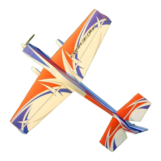
- Page 1 48" EPP Extra Electric ARF Assembly Manual Copyright 2015 EXTREME FLIGHT Greetings and congratulations on your purchase of the 3DHS 48 EPP Extra 330SC!
- Page 2 The 48" EPP Extra combines the best of the worlds of balsa and EPP foam! Utilizing a new foam formulation, the 48" Extra brings new stiffness and precision to this class of aircraft, and enhances the legendary durability of EPP construction. This airplane will become your go-to practice plane for down-low maneuvers and is a great low-stress 3D parkflyer.
- Page 3 -4S 2100-2350 mah LiPo battery. -APC 12x6 E prop (NOT the slow fly version!). -40 mm Extreme Flight spinner. -2 18"-24" extensions for the elevator and rudder servos and 2 6"-8" extensions to go between the receiver and the aileron servo leads. We recommend the 28 or 32 AWG...
- Page 4 -Adhesive backed Velcro and Velcro strap for battery retention. Let's begin! 1. Locate the 2 wing panels with ailerons as well as the 2 G10 aileron control horns. 2. Scuff the portion of the control horn that will be glued into the aileron with sandpaper.
- Page 5 4. Slide the aileron into position on the hinges and secure with several drops of fresh thin CA. This process is much easier and more effective if a fine glue tip is used. Make sure to deflect the surface back and forth while applying the 5.
- Page 6 each end of the pushrods and secure to the servo arm and control horn with the 2 mm hardware as shown in the picture. Use the longest arm provided with your servo. 6. Repeat this process for the other wing half. 7.
- Page 7 8. Install the wheel pants, spacers, wheels and wheel collars as shown.
- Page 8 9. Install plastic retaining strap to secure wheel pant as shown. 10. Locate tail wheel wire, tail wheel bracket, tail wheel, and tail wheel collar. Assemble as shown.
- Page 9 11. Locate rudder. Insert tail wheel wire into rudder as shown until it is fully seated. 12. Insert rudder into fuselage, glue hinges with thin CA.
- Page 10 13. Attach tailwheel bracket with wood screws as shown, making sure the rudder swings easily.
- Page 11 14. Install rudder control horn with medium CA as previously on aileron horns. 15. Install servo and linkage as shown, using hardware as previously on ailerons. NOTE: install servo wire extension on rudder servo with a lock. 16. Locate the stabilizer and elevator, separate them, and install the elevator through the slot in the fuselage as shown.
- Page 12 elevator upside-down and backwards when inserting and then flip it right way around after it's installed. 17. Insert the elevator into the slot and slide forward into place. Once fully seated in place, attach with a few drops of thin CA. 18.
- Page 13 19. Install elevator control horn, servo, and linkage as shown. Note: Install servo wire extension with a lock. 20. Insert brushless motor with mount into nose of aircraft and line up with mounting holes. Insert 3mm mounting screws and tighten as shown. NOTE: We highly recommend the Torque 2814-820 motor and AirBoss 45A ESC.
- Page 14 21. Mount the ESC under the battery tray with Velcro. Use adhesive Velcro and a Velcro strap to mount the battery as shown. Slide the wings onto the carbon wing tube and attach with screws as shown. NOTE: The carbon wing tube is NOT glued in place, it and the wings remain removable.
- Page 15 Set-up and flying tips The CG for the Extra is on the wing tube. There is plenty of room on the battery tray to move your battery to achieve this CG location. Depending on your flying style you can adjust the position of the battery to alter the CG to accommodate your preferences.
- Page 16 toward precision aerobatics then I recommend setting your CG using the 45 degree line test. Fly the aircraft from left to right or right to left, whichever direction you are more comfortable with at 3/4 to full throttle. Pull the aircraft to a 45 degree up line and establish this line and immediately roll the aircraft inverted.
Need help?
Do you have a question about the 3DHS 48 EPP EXTRA 330SC and is the answer not in the manual?
Questions and answers