
Related Manuals for Avdel 07412


Summary of Contents for Avdel 07412
- Page 1 I n s t r u c t i o n M a n u a l Pass onto user to read and keep for reference Threaded Insert Power Tool 07412...
- Page 2 AVDEL policy is one of continuous development. Specifications shown in this document may be subject to changes which may be introduced after publication. For the latest information always consult Avdel. S P E C I F I C A T I O N S F O R...
-
Page 3: Table Of Contents
O N T E N T S S A F E T Y General Specific to 07412 Tool I N T E N T O F U S E General Tool Dimensions P U T T I N G I N T O S E R V I C E... -
Page 4: General
RECOMMENDED AND SUPPLIED BY AVDEL. ANY MODIFICATION UNDERTAKEN BY THE CUSTOMER TO THE TOOL/MACHINE, NOSE ASSEMBLIES, ACCESSORIES OR ANY EQUIPMENT SUPPLIED BY AVDEL OR THEIR REPRESENTATIVES, SHALL BE THE CUSTOMER'S ENTIRE RESPONSIBILITY. AVDEL WILL BE PLEASED TO ADVISE UPON ANY PROPOSED MODIFICATION. -
Page 5: Specific To 07412 Tool
In addition to the general safety rules opposite, the following specific safety points must also be observed: THE OPERATING PRESSURE SHALL NOT EXCEED 7 BAR - 100 LBF/IN DO NOT OPERATE THE TOOL WITHOUT FULL NOSE EQUIPMENT IN PLACE. WHEN USING THE TOOL, THE WEARING OF SAFETY GLASSES IS REQUIRED BOTH BY THE OPERATOR AND OTHERS IN THE VICINITY TO PROTECT AGAINST FASTENER PROJECTION, SHOULD A FASTENER BE PLACED ‘IN AIR’. -
Page 6: General
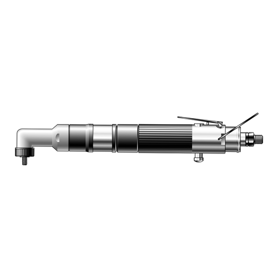
Use the selection table page 9 to select a complete tool which will be fitted with the correct nose equipment for the threaded insert selected. It is also possible to order the base tool only (part number 07412 - 00400). For details of nose equipment see pages 8 and 9. 12.5 2.13... -
Page 7: Air Supply
U T T I N G I N T O S E R V I C E A I R S U P P L Y All tools are operated with compressed air at an optimum pressure of 5.5 bar. We recommend the use of pressure regulators and automatic oiling/filtering systems on the main air supply. -
Page 8: Operating Procedure
O P E R A T I N G P R O C E D U R E I M P O R T A N T When placing Standard Nutserts, lubricate the drive screw of the tool every 25 placings. This is best achieved by wiping the drivescrew with a sponge soaked with STP Lubricant part number 07992-00013 OPTION 2 OPTION 1... -
Page 9: Clutch Adjustment - Accessories
C L U T C H A D J U S T M E N T Whether supplied as a assembly (part number 08412-00380) or within a complete tool, the clutch is supplied unset. Correct clutch setting is necessary to ensure optimum deformation of the insert. If the deformation is insufficient (clutch torque too low) the insert will rotate in the application. -
Page 10: Fitting/Servicing/Components
O S E E Q U I P M E N T If you have purchased a complete tool, it will already be fitted with the correct nose equipment for your insert. It is essential that the correct nose equipment is fitted prior to operating the tool. By knowing your original complete tool part number or the details of the insert to be placed, you will be able to order a complete combination of nose equipment by referring to the table opposite. - Page 11 S T A N D A R D N U T S E R T S ( 9 5 0 0 - 9 5 3 8 ) 3 0 - 3 5 0 7 4 1 2 - 0 0 0 1 6 07412-06106 07412-03805...
-
Page 12: Regular Servicing
E R V I C I N G T H E T O O L Regular servicing should be carried out and a comprehensive inspection performed annually or every 200000 cycles, whichever is soonest. I M P O R T A N T The employer is responsible for ensuring that tool maintenance instructions are given to the appropriate personnel. -
Page 13: Maintenance
M A I N T E N A N C E Every 200000 cycles the tool should be completely dismantled and components replaced where worn, damaged or when recommended. All ‘O’ rings and seals should be replaced with new ones and lubricated with Moly Lithium grease EP 3753 before assembling. I M P O R T A N T Safety Instructions appear on pages 2 &... - Page 14 CLUTCH ■ Remove cover 68 from clutch housing 11 and unscrew clutch housing 11 from ring gear 17 (left hand thread). ■ Remove drive plate 7 and pull out clutch assembly. ■ Remove ‘O’ ring 16 from clutch spindle 13. ■...
- Page 15 REAR GEAR ASSEMBLY ■ Pull off spacer 59. ■ Grip ring gear 63 and tap out the internal assembly from the front end. ■ Remove two bearings 21 and spacer 61 from planet gear spindle 20. ■ Push out two planet gear shafts 23 and slide out two planet gears 22 complete with needle bearings 60. ■...
-
Page 18: Fault Diagnosis Table
A U L T D I A G N O S I S F A U L T D I A G N O S I S T A B L E SYMPTOM POSSIBLE CAUSE REMEDY ➝ Insufficient air pressure ➝... - Page 19 Engineered Fastening and Assembly Systems Declaration of Conformity Avdel UK Limited, Mundells, Welwyn Garden City, Herts, AL7 1EZ declare under our sole responsibility that the product type 07412 Serial Nº ..........to which this declaration relates is in conformity with the following standards or other formative documents...
- Page 20 Tel: +82 31 798 6340 Email: info@acument.com.au Email: AvdelDeutschland@acument.com Fax: +82 31 798 6342 Email: info@acumentkorea.com CANADA ITALY Avdel Canada, a Division of Acument Avdel Italia S.r.l. SPAIN Canada Limited Viale Lombardia 51/53 Avdel Spain S.A. 87 Disco Road 20047 Brugherio (MI)
Need help?
Do you have a question about the 07412 and is the answer not in the manual?
Questions and answers