
Related Manuals for Avdel 74110


Summary of Contents for Avdel 74110
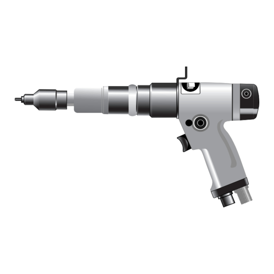
- Page 1 I n s t r u c t i o n M a n u a l O r i g i n a l I n s t r u c t i o n 7 4 1 1 0 T h r e a d e d I n s e r t P o w e r To o l...
-
Page 3: Table Of Contents
In the event of a defect or failure, and at its sole discretion, Avdel undertakes only to repair or replace faulty components. Avdel UK Limited policy is one of continuous product development and improvement and we reserve the right to change the specification of any product without prior notice. -
Page 4: Safety Rules
Do not use outside the design intent. Do not use equipment with this tool other than that recommended and supplied by Avdel UK Limited. Any modification undertaken by the customer to the tool/machine, nose assemblies, accessories or any equipment supplied by Avdel UK Limited or their representatives, shall be the customer’s entire responsibility. -
Page 5: Tool Specifications
S p e c i f i c a t i o n s To o l S p e c i f i c a t i o n Air Pressure Minimum - Maximum 4-6.3 bar (60/94 lbf/in Free Air Volume Required @ 6.3 bar / 94 lbf/in 7.5 litres/sec Motor Speed... -
Page 6: Intent Of Use
Use the selection table opposite to select a complete tool which will be fitted with the correct nose assembly for the threaded insert selected. ‘A’ and ‘B’ dimensions will help you assess the accessibility of your application. It is also possible to order the base tool only (part number 74110-12000). For details of Nose Assemblies see pages 11 and 12. -
Page 7: To O L S E L E C T I O N
I n t e n t o f U s e To o l S e l e c t i o n 74110 TOOL SELECTION UNSET NOSE (see drawing opposite for A & B) COMPLETE INSERT TORQUE CLUTCH PART Nº... -
Page 8: Putting Into Service
P u t t i n g i n t o S e r v i c e A i r S u p p l y All tools are operated with compressed air at an optimum pressure of 5.5 bar. We recommend the use of pressure regulators and automatic oiling/filtering systems on the main air supply. -
Page 9: Clutch Adjustment
P u t t i n g i n t o S e r v i c e C l u t c h A d j u s t m e n t If you have ordered a complete tool the clutch will be set for the specified insert. When purchased as a spare part, the clutch is supplied unset. -
Page 10: Nose Assemblies
N o s e A s s e m b l i e s Nose assemblies are specifically designed for each size and type of insert. If you have purchased a complete tool, it will already be fitted with the correct nose assembly for your insert. It is essential that the correct nose assembly is fitted prior to operating the tool. -
Page 11: Nose Assembly Components 11
N o s e A s s e m b l i e s N o s e A s s e m b l y C o m p o n e n t s The table below lists all nose assemblies available. Each nose assembly represents a unique assembly of components which can be ordered individually. - Page 12 N o s e A s s e m b l i e s NOSE ASSY 07556-09916 07001-00320 07440-08805 07007-00080 07007-00077 07521-08808 07521-08803 07443-08001 07556-09918 07001-00334 07551-08803 07007-00080 07007-00077 07522-08801 07443-08001 07556-09928 07001-00333 07551-08805 07007-00080 07007-00077 07522-08801 07443-08001 07556-09930 07001-00335 07551-08802 07007-00080 07007-00077...
-
Page 13: Servicing The Tool
S e r v i c i n g t h e To o l Regular servicing should be carried out and a comprehensive inspection performed annually or every 200000 cycles, whichever is soonest. I M P O R T A N T The employer is responsible for ensuring that tool maintenance instructions are given to the appropriate personnel. -
Page 14: Safety Data (Grease)
S a f e t y D a t a ( G re a s e ) M o l y - L i t h i u m G r e a s e E P 3 7 5 3 S a f e t y D a t a For lubricating internal tool parts other than those described previously, use Moly-Lithium Grease EP3753 (part number 07992-00020) First Aid SKIN:... -
Page 15: Maintenance
White numbers on black background indicate Number of turns. Black numbers on white background indicate expected Torque in 1bf ins. CLUTCH SPRING CIRCLIP 72 ADJUSTING RING 71 74110 CLUTCH DETAILS SPRING UNSET CLUTCH SPRING Nº OF TURNS/lb f ins PART Nº... -
Page 16: Clutch Assembly
Remove Clutch Spring 56, 57 or 69. • Assemble in reverse order, ensuring that Clutch Case 103 is tightened to the correct Torque (6.8Nm) as shown on assembly drawing 74110-12000 (s). 56 57 69 95 94 93 84 73 CLUTCH ASSEMBLY PARTS LIST... -
Page 17: Gearbox Assembly
With Key 59 in position slide Gear Case 60 over Bearing 67, and insert into Pistol Grip Body. • Tighten 60 to stated torque value. • Dismantle in reverse order. GEARBOX PARTS LIST AVDEL SUPPLIER ITEM PART No. DESCRIPTION PART No. -
Page 18: Motor Assembly
Fit Front Bearing Housing 53 to front of assembly. 117 54 POSITION OF BLADE 0.040 NOTCH UNIMPORTANT 0.025 MAXIMUM DIMENSION AFTER BEARING IS PRESSED ONTO ROTOR MOTOR ASSEMBLY PARTS LIST AVDEL SUPPLIER ITEM PART No. DESCRIPTION PART No. SPARES 305743 MOTOR COMPLETE... -
Page 19: Setting The Push Rod
M a i n t e n a n c e S e t t i n g t h e P u s h R o d • Apply shims and spacers to obtain a maximum axial clutch movement of 0.13mm Note: Shims must be adjacent to face of Bit Holder •... -
Page 20: General Assembly Of Base Tool
G e n e r a l A s s e m b l y o f B a s e To o l 7 4 1 1 0 - 1 2 0 0 0 ( s ) -
Page 21: Parts List
P a r t s L i s t f o r 7 4 1 1 0 - 1 2 0 0 0 ( s ) - Page 22 G e n e r a l A s s e m b l y o f B a s e To o l 7 4 1 1 0 - 1 2 0 0 0 ( s )
- Page 23 P a r t s L i s t f o r 7 4 1 1 0 - 1 2 0 0 0 ( s )
-
Page 24: Troubleshooting 24
(Standard Nutserts only) Insert thread restricted Change Inserts Drive screw thread worn Replace drive screw Incorrect insert/drive screw Replace with correct insert/drive screw continued overleaf Other symptoms or failures should be reported to your local Avdel authorised distributor or repair centre. - Page 25 Tool not held correctly Ensure tool is held square to application Incorrect insert/drive screw threads Replace with correct insert/drive screw Restricted insert threads Change batch of inserts Other symptoms or failures should be reported to your local Avdel authorised distributor or repair centre.
- Page 26 N o t e s...
- Page 27 D e c l a r a t i o n o f C o n f o r m i t y We, Avdel UK Limited, Watchmead Industrial Estate, Welwyn Garden City, Herts, AL7 1LY declare under our sole responsibility that the product: Model 74110 Serial No.
- Page 28 This document is for informational purposes only. Infastech makes no warranties, expressed or implied, in this document. Data shown is subject to change without prior notice as a result of continuous product development and improvement policy. Your local Avdel representative is at your disposal should you need to confirm latest information.
Need help?
Do you have a question about the 74110 and is the answer not in the manual?
Questions and answers