Table of Contents

Related Manuals for Avdel 71234


Summary of Contents for Avdel 71234
- Page 1 I n s t r u c t i o n M a n u a l O r i g i n a l I n s t r u c t i o n 7 1 2 3 4 To o l 7 1 2 3 3 To o l Genesis ®...
-
Page 3: Table Of Contents
AND REMEDIES. ANY IMPLIED WARRANTY AS TO QUALITY, FITNESS FOR PURPOSE, OR MERCHANTABILITY ARE HEREBY SPECIFICALLY DISCLAIMED AND EXCLUDED BY AVDEL. Avdel UK Limited policy is one of continuous product development and improvement and we reserve the right to change the specification of any product without prior notice. -
Page 4: Safety Instructions
Any modification undertaken by the customer to the tool/machine, nose assemblies, accessories or any equipment supplied by Avdel UK Limited or their representatives, shall be the customer’s entire responsibility. Avdel UK Limited will be pleased to advise upon any proposed modification. -
Page 5: Tool Specification
S p e c i f i c a t i o n s To o l S p e c i f i c a t i o n Air Pressure Minimum - Maximum 5-7 bar Free Air Volume Required @ 5.5 bar 4.3 litres Stroke... -
Page 6: Intent Of Use
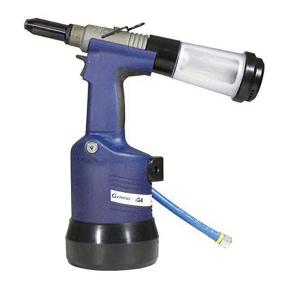
R a n g e o f F a s t e n e r s ® nG4 is a hydro-pneumatic tool designed to place Avdel breakstem fasteners at high speed making it ideal for batch or flow-line assembly in a wide variety of applications throughout all industries. It can place all fasteners listed opposite. -
Page 7: Putting Into Service
P u t t i n g i n t o S e r v i c e A i r S u p p l y All tools are operated with compressed air at an optimum pressure of 5.5 bar. We recommend the use of pressure regulators and filtering systems on the main air supply. -
Page 8: Operating Procedure
P u t t i n g i n t o S e r v i c e O p e r a t i n g P ro c e d u r e • Ensure that the correct nose assembly suitable for the fastener is fitted. •... -
Page 9: Nose Assemblies
N o s e A s s e m b l i e s N o s e T i p S e l e c t i o n I M P O R T A N T Nose assemblies do NOT include nose tips. Nose tips must be ordered separately. A tool must always be fitted with the correct nose assembly and nose tip for your fastener and must be ordered separately, refer to the ‘NOSE TIPS’... -
Page 10: T Y P E 1
07 381 -0 470 1 12 .7 2 .8 … 0 1 0 LOCKING RING 07340-00327 Al Alloy 07 612 -0 200 1 12 .7 2 .8 … 0 2 1 COMPLETE TOOL PART NUMBER : precede with 22.9 71233-00 71234-00... - Page 11 07003-00067 precede with APPLICATIONS WHERE TYPE 1 JAW HOUSING 07340-00304 71233-00 NOSE TIPS WILL NOT REACH. JAWS 71210-15001 JAW SPREADER 07498-04502 71234-00 BUFFER 71210-05001 SPRING 07500-00418 LOCKING RING 07340-00327 22.9 17 JAW SPREADER HOUSING 71210-02101 17 18 6 5 4 58.3...
- Page 12 N O S E A S S E M B LY 0 76 10-02 100 … 3 7 2 In inches then in millimetres COMPLETE TOOL PART NUMBER : precede with 71233-00 or 71234-00 NOSE ASSEMBLY NOSE ASSEMB LY part nº 07610-02000 for " ø...
- Page 13 N o s e A s s e m b l i e s F i t t i n g i n s t r u c t i o n f o r A v t a i n e r ®...
-
Page 14: Accessories
STEM DEFLECTOR STEM DEFLECTOR 07340-00342 07340-00342 ADAPTOR NUT ADAPTOR 71210-20101 71213-20103 71233 Tool 71234 Tool • • Fit Stem Deflector (07340-00342) into Adaptor (71213-20103). Fit Stem Deflector (07340-00342) into Adaptor (71210- • 20101). Screw Adaptor onto End Cap Assembly 71233-05103. •... - Page 15 N o t e s...
-
Page 16: Servicing The Tool
S e r v i c i n g t h e To o l I M P O R T A N T Read Safety Instructions on page 4. The employer is responsible for ensuring that tool maintenance instructions are given to the appropriate personnel. The operator should not be involved in maintenance or repair of the tool unless properly trained. -
Page 17: Molykote ® 55M Grease Safety Data
S e r v i c i n g t h e To o l M o l y k o t e ® 5 5 m G r e a s e S a f e t y D a t a First Aid SKIN: Flush with water. -
Page 18: Service Kit
S e r v i c i n g t h e To o l S e r v i c e K i t For an easy complete service, Avdel offers the complete service kit below. SERVICE KIT : 71210-99990 Spanners are specified in inches and across flats unless otherwise stated PART Nº... -
Page 19: Dismantling The Tool
• Unscrew End Cap Assembly 4 together with ‘O’ Rings 2, 3 and Lip Seal 1. 71234 Tool with Fixed Stem Collector Bottle • Rotate the Stem Collector Outer so that the aperture in the stem Collector Body is fully exposed. -
Page 20: Pneumatic Piston Assembly
S e r v i c i n g t h e To o l P n e u m a t i c P i s t o n A s s e m b l y • Remove ‘ON/OFF’ Valve Assembly 62. •... -
Page 21: Rotary Valve
S e r v i c i n g t h e To o l R o t a r y Va l v e Dismantling • Remove Pneumatic Piston Assembly 57 as described in Pneumatic Piston Assembly. • Using Spanner (07900-00672), and Location Spigot Assembly (07900-00706), unscrew Clamp Nut 39 and remove together with Top Plate Assembly 44 together with Tie Rods 56, Transfer Tube Assembly 61, seperate Body 30 from Handle Assembly 64. -
Page 22: Common Parts
C o m m o n P a r t s G e n e r a l A s s e m b l y o f C o m m o n P a r t s 7 1 2 3 3 - 0 2 0 0 0 a n d 7 1 2 3 4 - 0 2 0 0 0... -
Page 23: Parts List For Common Parts 71233-02000
C o m m o n p a r t s P a r t s L i s t f o r C o m m o n P a r t s 7 1 2 3 3 - 0 2 0 0 0 a n d 7 1 2 3 4 - 0 2 0 0 0... -
Page 24: Stem Collector Bottles Removable And Fixed
S t e m C o l l e c t o r B o t t l e s R e m o v a b l e a n d F i x e d 7 1 2 3 3 To o l R e m o v a b l e 91 Ref see page 22 REMOVABLE STEM COLLECTOR BOTTLE ITEM... -
Page 25: Oil Details
P r i m i n g Priming is ALWAYS necessary after the tool has been dismantled and prior to operating. It may also be necessary to restore the full stroke after considerable use, when the stroke may have been reduced and fasteners are not now being fully placed by one operation of the trigger. -
Page 26: Priming Procedure
P r i m i n g P r i m i n g P ro c e d u r e I M P O R T A N T DISCONNECT THE TOOL FROM THE AIR SUPPLY OR SWITCH OFF AT ON/OFF VALVE ASSEMBLY 62. REMOVE NOSE ASSEMBLY . - Page 27 Low oil level or air present in oil Prime tool 25, 26 Item numbers in bold refer to the general assembly drawing and parts list on pages 22 and 23. ® Other symptoms or failures should be reported to your local Avdel authorised distributor or repair centre.
- Page 28 D e c l a r a t i o n o f C o n f o r m i t y We, Avdel UK Limited, Watchmead Industrial Estate, Welwyn Garden City, Herts, AL7 1LY declare under our sole responsibility that the product: Model nG4 Serial No.
- Page 29 N o t e s...
- Page 30 This document is for informational purposes only. Infastech makes no warranties, expressed or implied, in this document. Data shown is subject to change without prior notice as a result of continuous product development and improvement policy. Your local Avdel representative is at your disposal should you need to confirm latest information.
Need help?
Do you have a question about the 71234 and is the answer not in the manual?
Questions and answers