
Related Manuals for Mega Lite Drama W50 LED


Summary of Contents for Mega Lite Drama W50 LED
-
Page 1: Table Of Contents
USER MANUAL Table of Contents Safety Information Specifications Main Power Connection DMX-512 Connection Mounting Controller DMX Profile Main Control Menu Rigging the Fixture Cleaning & Maintenance Parts List... -
Page 3: Safety Information
Check that the unit has not been damaged during transport Protection Against Fire 1. Maintain a minimum of 1 foot distance from any type of flame. 3. Replace fuse only with the specified type and rating. 4. Do Not install the unit to close to a heat source. 5. -
Page 4: Specifications
Technical Information Part Numbers Fixture 7050-Drama LED W50 7051-Drama LED W50 With DMX Controller 7052-Drama LED W50 White Housing 7053-Drama LED W50 With DMX Controller White Housing Mechanical Specifications 7.75” (lens out) 4.75” (no power) 8” DMX Connectors: 3 or 5-pin XLR connectors in/out (specified at ordering) Power Connections: Nema 5-15 to screw type base connector cable mounted Thermal: Maximum ambient temperature 40°... -
Page 5: Main Power Connection
Main Power Connection Caution! Do not connect fixture to a dimmer system. This unit has Auto switching power supply. It will respond to 110V or 220V automatically This unit must be earthed. (electronically grounded) Replace fuse only with the specified type and rating. The occupation of the connection-cable is as follows: This fixture is equipped with an electronic power supply that will let the unit operate from 100V to 240V from 50Hz to Cable (USA) -
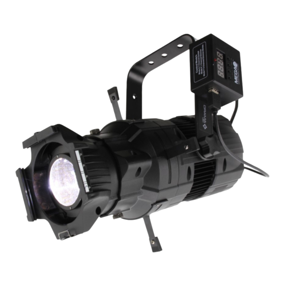
Page 6: Mounting Controller
Mounting DMX Controller The mounting of the DMX controller should be mounted on the side of the yoke. There is a left and right position for the mounting. If the yoke is in the down position the DMX Controller should be mounted on the right side. If yoke is on the Up positon then the controller should be mounted on the left side. -
Page 7: Main Control Menu
Main Control CONTROL BOARD The control board on the fixture base is your interface to access and control all the functions on the unit. Its digital display gives you a code view of the options and functions. The following will explain each func- tion and its options. -
Page 8: Rigging The Fixture
Rigging the fixture Caution! 1. The installations must be carried out by an authorized dealer or trained profes- sional. 2. Unit may cause severe injures if you have doubts concerning the safety do not install. When rigging a unit it is very important that you follow common safety procedures. Rigging requires extensive experi- ence including but not limited to calculating working loads, material being used and periodic safety inspections. -
Page 9: Warranty Information
Warranty Information Warranty Conditions -Unless otherwise stated in writing, your product is covered by a one year parts and labor limited warranty. -LEDs are not guaranteed to match in color temperature or output. -It is the owner’s responsibility to furnish receipts or invoices for verification of purchase, date, and reseller or distributor. If purchase date cannot be provided, date of manufacture will be used to determine warranty period.
Need help?
Do you have a question about the Drama W50 LED and is the answer not in the manual?
Questions and answers