Table of Contents
Advertisement
Available languages
Available languages
Quick Links
Please read all instructions before installing
SPECIFICATIONS
Voltage ........................................................................ 120VAC, 60Hz
Load (Multi-Way)
Incandescent or fluorescent ...................................... 0-600 Watts
Fan motor ............................................................................ 1/6 hp
Time Delay Adjustment .................... 15 sec., 5 min., 15 min., 30 min.
Light Level Adjustment ................................................. 10 fc to 150 fc
Environment ............................................................... Indoor use only
Operating Temperature ..........................32° to 131°F (0° to 55°C)
Humidity ................................................ 95% RH, non-condensing
Tools Needed
Insulated Screwdriver
Wire Strippers
DESCRIPTION AND OPERATION
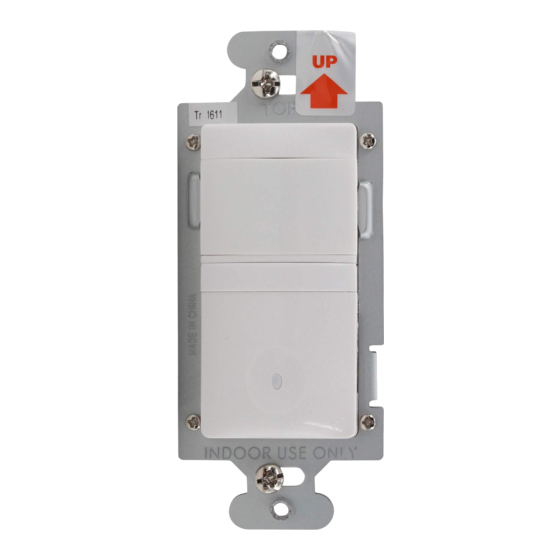
RH-250 Multi-way Wall Switch Convertible Occupancy Sensors are designed
to replace standard single pole and multi-way (3-way, 4-way) switches. They
are ideal for any room with multiple entries and any other indoor space where
vacancy sensor-based controls with manual ON/OFF capability are desirable.
Like standard switches, you can press the ON/OFF button to turn the light or fan
(controlled load) ON and OFF. Unlike standard switches, the RH-250 automatically
turns OFF the controlled load after the coverage area has been vacant for a period
of time (Time Delay). If motion is detected within 30 seconds after it automatically
turns OFF, the RH-250 automatically turns the load back ON.
While the sensor is factory preset as a Vacancy Sensor with manual ON operation,
it can be adjusted to work as an occupancy sensor that turns the controlled load
ON automatically upon detection of occupancy in the area.
The RH-250 can be wired with up to three additional RH-250s for multi-way
Manual/Auto–ON/OFF of one or several loads (up to one load connected to each
RH-250). It can also be wired to up to four RH-253 single pole momentary wall
switches for multi-way Manual-ON/OFF Automatic-OFF control of one load.
Lighted Switch
To help you locate the RH-250 in a dark room, the amber LED illuminates the
ON/OFF button while the controlled load is OFF. When the controlled load is ON,
the LED is OFF.
Operating Modes
For multi-way operation of two or more RH-250s, we recommend that the
Operating Mode be the same in all sensors related to the same load. This
makes it easier to understand the multi-way control operation as well as trouble
shooting. There are two operating modes to select from:
MODE 1 Vacancy sensor (Manual-ON/OFF, Auto-OFF): The user must press
the ON/OFF button to turn the load ON. The RH-250 keeps the load ON until no
motion is detected by any of the related RH-250s for the time delay period. There
is also a 30 second reset delay after the automatic shut-off. If motion is detected
during this time, the sensor turns the load back ON automatically. After the 30
second reset delay has elapsed, the ON/OFF button must be pressed to turn ON
the load.
MODE 2 Occupancy sensor (Auto-ON/OFF with manual control and reset to auto
Call 800.879.8585 for Technical Support
Multi-Way Wall Switch
Occupancy Sensor
Santa Clara, CA 95050
RH-250
Convertible
Advertisement
Table of Contents

Subscribe to Our Youtube Channel
Related Manuals for wattstopper RH-250-W


Summary of Contents for wattstopper RH-250-W
- Page 1 Please read all instructions before installing RH-250 Multi-Way Wall Switch Convertible Occupancy Sensor SPECIFICATIONS Voltage ................ 120VAC, 60Hz Load (Multi-Way) Incandescent or fluorescent ........0-600 Watts Fan motor ................1/6 hp Time Delay Adjustment ....15 sec., 5 min., 15 min., 30 min. Light Level Adjustment ..........
-
Page 2: Time Delay
A neutral wire should also be present in both wall boxes. Lamp/load MASTER SWITCH AUXILIARY SWITCH TRAVELER TRAVELER NEUTRAL LOAD/Common (power to lamp) GROUND HOT/Common GROUND (power from circuit box) Fig. 2: Typical 3-Way Switch Wiring www.wattstopper.com... - Page 3 CAUTION For your safety: Connecting a proper ground to the sensor provides protection against electrical shock in the event of certain fault conditions. If a proper ground is not available, consult with a qualified electrician before continuing installation. Strip Gage 3.
-
Page 4: Initial Power-Up
ON. 8. Install cover plates. However, the lights can be turned Install industry standard decorator wall ON/OFF manually by pressing the switch cover plate (not included) “ON/OFF Button” at any time when power is supplied to the unit. www.wattstopper.com... - Page 5 SENSOR ADJUSTMENT & PROGRAMMING To program the RH-250, you use controls located under the ON/OFF button. The wall switch cover plate must be removed to gain access to the mode button and adjustment trimpots under the ON/OFF button. For multi-way operation, the Operating Mode and the Time Delay Lock Bar adjustments should be the same in all...
-
Page 6: Test Mode
If load does not respond properly after following troubleshooting, turn OFF power to the circuit then check wire connections or call technical support. COVER PLATES WattStopper RH wall switches fit behind industry standard decorator style switch cover plates. WARRANTY INFORMATION WattStopper warranties its products to be free of defects in materials and workmanship for a period of five (5) years. - Page 7 Por favor leer todas las instrucciones antes de realizar la instalación RH-250 Sensor de Desocupación de pared (3 vías, 4 vías) configurable ESPECIFICACIONES Voltaje ................120VAC, 60Hz Carga (3 vias, 4 vias) Lámparas incandescentes o fluorescentes ....0-600 Watts Un motor ................... 1/6 hp Ajuste del Retardo de Apagado ..desde 15 segundos hasta 30 minuto Ajuste del Nivel de Luz Natural .........
- Page 8 Un cable o alambre de conexión a tierra también puede estar presente en las cajas de conexiones y conectado a las terminales de tierra de los interruptores de 3 vías existentes. Un cable o alambre de conexión a neutro también debe estar presente en ambas cajas de conexiones. www.wattstopper.com...
- Page 9 INTERRUPTOR MAESTRO INTERRUPTOR AUXILIAR VIAJERO NEUTRO VIAJERO CARGA/Alambre Común (Energía a la lámpara) TIERRA TIERRA LINEA/FASE/Alambre Común Fig. 2: Conexión típica de dos interruptores de 3 vías (proveniente de la caja de disyuntores o "breakers" CUIDADO Por su propia seguridad: el conectar el sensor apropiadamente a tierra provee protección contra un choque eléctrico que pueda ocurrir en caso de una operación defectuosa.
- Page 10 2 (ENCENDIDO/APAGADO Automático). Esto se debe a un periodo de calentamiento inicial necesario que puede durar hasta 1 minuto. Durante este intervalo de tiempo, sin embargo, continúa siendo posible el encender o apagar las luces manualmente con solo presionar el botón de ENCENDIDO/APAGADO. www.wattstopper.com...
-
Page 11: Selección Del Modo De Operación
CONFIGURACIÓN Y PROGRAMACIÓN DEL SENSOR Para configurar el sensor RH-250 usted debe utilizar los controles ubicados detrás del botón de ENCENDIDO/APAGADO. Es necesario desmontar la placa decorativa para obtener acceso al Botón de Selección de Modos y a las Perillas de Ajuste. Barra de Seguridad Se recomienda que todos los RH-250 en una conexión de 3 o 4 vías esten... -
Page 12: Modo De Prueba
(breaker) y revise las conexiones de los cables o llame al 800.879.8585 para recibir asistencia técnica. PLACAS DECORATIVAS Utilice placas decorativas estándar con los sensores RH de WattStopper. INFORMACIÓN SOBRE LA GARANTIA DE PRODUCTO WattStopper garantiza que sus productos están libres de defectos en sus materiales y ensamble por un período de cinco (5) años.
Need help?
Do you have a question about the RH-250-W and is the answer not in the manual?
Questions and answers