Table of Contents
Advertisement
Quick Links
Advertisement
Table of Contents

Related Manuals for TYAN GN70-B8236-HE


Summary of Contents for TYAN GN70-B8236-HE
- Page 1 GN70-B8236-HE Service Engineer’s Manual http://www.tyan.com...
- Page 2 http://www.tyan.com...
- Page 3 Corporation and has been reviewed for accuracy and reliability prior to printing. MiTAC assumes no liability whatsoever, and disclaims any ® express or implied warranty, relating to sale and/or use of TYAN products including liability or warranties relating to fitness for a particular purpose or merchantability.
- Page 4 There will be danger of explosion if battery is incorrectly replaced. Replace only with the same or equivalent type recommended by manufacturer. Dispose of used battery according to manufacturer instructions and in accordance with your local regulations. http://www.tyan.com...
-
Page 5: About This Manual
About this Manual This manual provides you with instructions on installing your TYAN GN70-B8236-HE. This Manual is intended for experienced users and integrators with hardware knowledge of personal computers. This manual consists of the following parts: Chapter1: Provides an introduction to the TYAN GN70-B8236-HE... -
Page 6: Safety And Compliance Information
Safety and Compliance Information Before installing and using TYAN GN70-B8236-HE, take note of the following precautions: ·Read all instructions carefully. ·Do not place the unit on an unstable surface, cart, or stand. ·Do not block the slots and opening on the unit, which are provided for ventilation. -
Page 7: Safety Information
To reduce the risk of bodily injury, electric shock, fire and damage to the equipment, observe all precautions included in this guide. You must become familiar with the safety information in this guide before you install, operate, or service TYAN products. Symbols on Equipment Caution. This symbol indicates a potential hazard. - Page 8 · Make sure racks are coupled together if it is a multiple-rack installation. · Make sure the rack is level and stable before installing an appliance in the rack. · Make sure the leveling jacks are extended to the floor. http://www.tyan.com...
- Page 9 · Plug the power cord into a grounded (earthed) electrical outlet that is easily accessible at all times. · In all European electrical environments, you must ground the Green/Yellow tab on the power cord. If you do not ground the http://www.tyan.com...
- Page 10 TYAN, your authorized TYAN partner, or their agents. Equipment Modifications · Do not make mechanical modifications to the system. TYAN is not responsible for the regulatory compliance of TYAN equipment that has been modified.
- Page 11 – Liquid has been spilled on the product or an object has fallen into the product. – The product has been exposed to rain or water. – The product has been dropped or damaged. – The product does not operate normally when you follow the operating instructions. http://www.tyan.com...
- Page 12 http://www.tyan.com...
-
Page 13: Table Of Contents
Table of Contents Chapter 1: Overview ............... 15 About the TYAN GN70-B8236-HE ......... 15 Product Models............... 15 Features ................16 Standard Parts List ..............20 1.4.1 Box Contents ..............20 1.4.2 Accessories ..............22 About the Product ..............24 1.5.1 System Front View............ - Page 14 Fan BP Board LED Definitions ........73 Replacing the HDD Backplane Board ........74 3.9.1 HDD BP Board Specifications ......... 75 3.9.2 HDD BP Board LED Definitions........76 Appendix I: Cable Connection Tables .......... 79 Appendix II: Technical Support............. 81 http://www.tyan.com...
-
Page 15: Chapter 1: Overview
IT demand but also offers a smooth path for future application usage. ® TYAN also offers the GN70-B8236-HE in a version that can support up to eight 3.5” hot-swap hard drives. The GN70-B8236-HE uses TYAN’s latest chassis featuring a robust structure and a solid mechanical enclosure. All of this provides GN70-B8236-HE the power and flexibility to meet the needs of nowadays server application. -
Page 16: Features
Features TYAN GN70B8236 (B8236G70W8HR-HE) 2U Rackmount Form Factor Chassis Model GN70 Dimension (D x W x 27.56" x 17.72" x 3.43" (700 x 450 x 87mm) System Motherboard S8236WGM3NR-HE EEB, 12"x13" (305x330mm) Board Dimension 25 kg Gross Weight Buttons (1) RST / (1) ID / (1) PWR w/ LED... - Page 17 Memory voltage 1.5V or 1.35V PCI-E (3) PCI-E Gen.2 x16 slots (1) M2201-L16-2F, PCI-E x16 2U riser card (left) / Pre-install TYAN Expansion Slots (2) M2202-R16-2F, PCI-E x16 2U riser card (right) Riser Card Max. HBA (6) 111.15mm x 167.65mm (FH/HL)
- Page 18 / User-configurable H/W monitoring / Auto-configurable of hard disk types Operating Please refer to our OS supported list. OS supported list System Class A FCC (DoC) Regulation CE (DoC) Operating Temp. 10° C ~ 35° C (50° F~ 95° F) Operating http://www.tyan.com...
- Page 19 Complaint Barebone (1) GN70B8236 Barebone (1) MB User's manual + (1) BB User's manual Manual Installation CD (1) TYAN installation CD Package Heatsink / Cooler (2) G34 CPU heatsinks Contains (1) CRAL-0031, sliding rail kit for KGT24/ KGT62 Rail kit...
-
Page 20: Standard Parts List
Standard Parts List This section describes GN70-B8236-HE package contents and accessories. Open the box carefully and ensure that all components are present and undamaged. The product should arrive packaged as illustrated below. 1.4.1 Box Contents Component Description 2U chassis, (8) hot swap HDD bays ®... - Page 21 M2202-R8-2F riser card (pre-installed) http://www.tyan.com...
-
Page 22: Accessories
If any items are missing or appear damaged, contact your retailer or browse to ® TYAN ’s website for service: http://www.tyan.com ® The web site also provides information of other TYAN products, as well as FAQs, compatibility lists, BIOS settings, etc. ® TYAN Motherboard... - Page 23 SGCC Bracket_L SGCC Bracket_R AC Power Cord 125V AC Power Cord 250V (US) (Europe) Barebone Manual Mainboard Manual Addendum for China Use Only http://www.tyan.com...
-
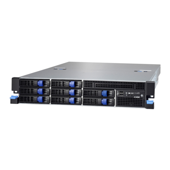
Page 24: About The Product
About the Product The following views show you the product. 1.5.1 System Front View Ears 3.5” HDD bays USB Ports ID Button NMI Button RESET Button NIC1/NIC2/NIC3 ID LED Warning LED BMC LED (reserved) Power On/OFF Button with LED http://www.tyan.com... - Page 25 Blinking Green LAN active Green LAN linked NIC2 LAN not linked Blinking Green LAN active NIC3 Green LAN linked LAN not linked Fan fail /Over temperature Warning /Over voltage No failure Blue System identified ID LED System not identified http://www.tyan.com...
- Page 26 Color: Amber Color: Green No Driver Present or power disconnected OFF OFF Driver Present No Activity OFF ON Access Activity OFF Blinking HDD Fail On Solid OFF Identify (Locate the HDD) Blinking(1Hz) x SAS/SATA RAID Building Blinking(4Hz) x http://www.tyan.com...
-
Page 27: System Rear View
Green Amber 1000Mb linked RJ-45 Green 100Mb linked Linkage(Right) 10Mb mode or No LAN Disabled linked NOTE: “Left” and “Right” are viewed from the rear panel. ID LED State Color Description Blue System identified ID LED System not identified http://www.tyan.com... -
Page 28: Motherboard (S8236) Layout
1.5.3 Motherboard (S8236) Layout The diagram is representative of the latest board revision available at the time of publishing. The board you receive may not look exactly like the above diagram. http://www.tyan.com... -
Page 29: Jumpers & Connectors
Power On LED (Green) LED5 Standby LED (Green) LED6 SAS Error LED (Amber) LED7 SAS Heart Beat LED (Green) LED8 BMC Heart Beat LED (Green) Jumper Legend OPEN - Jumper OFF Without jumper cover CLOSED - Jumper ON With jumper cover http://www.tyan.com... -
Page 30: System Block Diagram (S8236)
1.5.5 System Block Diagram (S8236) http://www.tyan.com... -
Page 31: Internal View
1.5.6 Internal View With Riser Card Brackets 3.5” HDD cage (underneath) SAS/SATA HDD Backplane Board System Fan Unit Power Distribution Board PCI-E Riser Card Bracket Power Supply (underneath) http://www.tyan.com... - Page 32 Without Riser Card Brackets 3.5” HDD cage (underneath) SAS/SATA HDD Backplane Board System Fan Unit Power Distribution Board Power Supply (underneath) http://www.tyan.com...
-
Page 33: Chapter 2: Setting Up
A grounding strap or an anti-static pad Most of the electrical and mechanical connections can be disconnected with your hands. It is recommended that you do not use pliers to remove connectors as it may damage the soft metal or plastic parts of the connectors. http://www.tyan.com... -
Page 34: Precautions
Working on a system that is connected to a power supply can be extremely dangerous. Follow the guidelines below to avoid damage to GN70-B8236-HE or injury to yourself. Ground yourself properly before removing the top cover of the system. -
Page 35: Installing Motherboard Components
CPUs, memory modules, HDD and PCI-E cards. 2.1.1 Removing the Chassis Cover Follow these instructions to remove the GN70-B8236-HE chassis cover. Unscrew the rear top cover on the back side. Unscrew the front top cover and pull the latches aside to lift up the top cover. - Page 36 Slide the rear top cover out. http://www.tyan.com...
-
Page 37: Removing The Riser Card Brackets
2.1.2 Removing the Riser Card Brackets Follow these instructions to remove the PCI-E Riser Card Brackets. Loose four thumb screws to release the PCI-E Riser Card Brackets. Lift up the Riser Card Brackets. http://www.tyan.com... -
Page 38: Installing The Cpu And Heatsink
Follow the steps below on installing CPUs and CPU heatsinks. Locate the CPU sockets. Pull the lever slightly away from the socket and then push it to a fully open position. Push the CPU socket cover to a fully open position. http://www.tyan.com... - Page 39 Take out the protection cap. Place the CPU into the socket and make sure that the gold arrow is located in the right direction. Close the CPU socket cover and press the lever down to secure the CPU. http://www.tyan.com...
- Page 40 Position the heatsink on top of the CPU and secure it with 2 screws. Repeat the procedures mentioned earlier to install the second CPU and heatsink. http://www.tyan.com...
-
Page 41: Installing The Memory
Align the memory module with the slot. When inserted properly, the memory slot locking levers lock automatically onto the indentations at the ends of the module. Follow the recommended memory population table to install the other memory modules. http://www.tyan.com... - Page 42 Memory Population Option Table The following pictures show common types of DDR3 memory modules. http://www.tyan.com...
- Page 43 4. Dual-rank DIMMs are recommended over single-rank DIMMs 5. Un-buffered DIMM can offer slightly better performance than registerd DIMM if populating only a single DIMM per channel 6. We don't suggest other memory installation. 7. AMD 6100 series CPU doesn't support Quad-ranks U-DIMM http://www.tyan.com...
- Page 44 SR and DR UDDR3 module support only x8 DRAM module support only SR and DR 1.35v Memory MAX speed of 1066MHz in a dual channel configuration SR and DR 1.5v Memory MAX speed of 1333MHz in a dual channel configuration http://www.tyan.com...
- Page 45 SR and DR 1.5v Memory MAX speed of 1333MHz in a dual channel configuration QR Memory has a MAX amount of 32GB per channel QR 1.35v Memory MAX speed of 800MHz in a dual channel configuration QR 1.5v Memory MAX speed of 1066MHz in a dual channel configuration http://www.tyan.com...
-
Page 46: Installing Hard Drives
2.1.4 Installing Hard Drives The GN70-B8236-HE can support up to eight (8) 3.5” hard drives. Follow these instructions to install a hard drive. Warning!!! Always install the hard disk drive to the chassis after the chassis is secured on the rack. - Page 47 Remove the 6 screws. Place a hard drive into the drive tray. Use 6 HDD screws to secure the HDD. http://www.tyan.com...
- Page 48 Reinsert the HDD tray into the chassis and press the locking lever to secure the tray. http://www.tyan.com...
-
Page 49: Installing The Pci-E Cards
2.1.5 Installing the PCI-E Cards The GN70-B8236-HE supports three PCI-E Riser Card Brackets. Follow these instructions to install PCI-E cards. Unscrew the PCI-E slots to take out the PCI brackets. Insert the PCI-E cards and securely screw as shown. Repeat the same procedures for the second and third Riser Card Brackets. -
Page 50: Rack Mounting
Sliding Rail x 2 Front view 2.2.1 Installing the Server in a Rack Follow these instructions to mount the TYAN GN70-B8236-HE into an industry standard 19” rack. NOTE: Before mounting the TYAN GN70-B8236-HE in a rack, ensure that all internal components have been installed and that the unit has been fully tested. - Page 51 Repeat the same procedures for the front end of the rail. Front Push the locking latch to secure the rail to the rack. Repeat the same procedures for the other rail. Left Right http://www.tyan.com...
- Page 52 There are three holes on each rail which are used to hook and secure the chassis. Align the studs on the chassis with the holes on the rails and make sure the chassis is securely hooked. http://www.tyan.com...
- Page 53 Push the chassis back into the rack. The installation is now complete. http://www.tyan.com...
-
Page 54: Removing The Server From A Rack
2.2.2 Removing the Server from a Rack Follow these instructions to remove the TYAN GN70-B8236-HE from an industry standard 19” rack. Push the ears to pull the chassis forward. Push forward the locking tabs on both rails to unhook the chassis from the rails. - Page 55 Follow the steps described earlier in reverse to remove the chassis from the rack. NOTE: To avoid injury, it is strongly recommended that at least two people lift the TYAN GN70-B8236-HE to hook on or unhook from the rails. http://www.tyan.com...
- Page 56 NOTE http://www.tyan.com...
-
Page 57: Chapter 3: Replacing Pre-Installed Components
This chapter explains how to replace the pre-installed components, including S8236 Motherboard, M1709G70-FPB Front Panel Board, PCI-E Riser Card, M1245G70-BP6-8 SATA/SAS HDD Board, System Fan and Power Supply Unit etc. Disassembly Flowchart The following flowchart outlines the disassembly procedure. http://www.tyan.com... -
Page 58: Removing The Cover
Follow these instructions to replace motherboard components, including the motherboard. 3.4.1 Replacing PCI-E Riser Card Cards The GN70-B8236-HE has three pre-installed PCI-E×16 riser cards. Follow the instructions below to disassemble the M2201-L16-2F and M2202-F16-2F PCI-E riser cards. Unscrew to take out the PCI-E cards. - Page 59 Repeat the same procedures for the second and third Riser Card Brackets. Unscrew the M2202-F16-2F riser card to replace a new one if necessary. http://www.tyan.com...
-
Page 60: Disconnecting All Motherboard Cables
Before replacing the motherboard or certain components, remove cables connected to the motherboard. Follow these instructions to remove all cables. Disconnect the power and PSMI cables. Disconnect the Mini SAS, USB, fan control and front panel cables. Disconnect the power cable. http://www.tyan.com... -
Page 61: Removing The Motherboard
After removing all of the aforementioned cables, follow the instructions below to remove the motherboard from the chassis. Remove the heatsinks and processors if installed. Remove the nine screws securing the motherboard to the chassis. Carefully lift the motherboard from the chassis. http://www.tyan.com... -
Page 62: Replacing The Power Distribution Board
Replacing the Power Distribution Board Follow these instructions to replace the M1601T70-D-PDB power distribution board. Disconnect all cables. Unscrew to replace a new power distribution board. http://www.tyan.com... -
Page 63: Replacing The Front Panel Board
Follow these instructions to replace the M1709G70-FPB Front Panel Board. Unscrew to release the Front Panel Board Module. Push the Front Panel Board Module forward. Disconnect the Front Panel Control and USB cables. Unscrew the Front Panel Board to replace a new one. http://www.tyan.com... - Page 64 Follow the steps described earlier in reverse to reinstall the Front Panel Board. http://www.tyan.com...
-
Page 65: Front Panel Board Specifications
Power On/Off LED Color: Green (after power on) ID LED Color: Blue LEDs Warning (IPMI) LED Dual Color: Yellow (Warning) / Green(Normal) RESET button Push buttons ID button Power On/Off button with Power On/Off LED http://www.tyan.com... -
Page 66: Fpb Led And Connector Pin Definition
*: For more information on the Chassis Locate LED, please visit our Web site for the latest Pilot II Software Configuration Guide. Front Panel Connector (J3) Definition Definition PW_LED+ ID_LED+ PW_LED- ID_LED- HD/LAN3_LED+ SYS_FAULT1- HD/LAN3_LED- SYS_FAULT2- PWR_SW+ LAN1_LED+ PWR_SW- LAN1_LED- RESET+ ICH_SMBDAT RESET- ICH_SMBCLK ID_SW+ INTRU# Temp_sensor LAN2_LED+ EXT_INT LAN2_LED- http://www.tyan.com... - Page 67 USB Connector (J1) Definition Definition USB1- USB2- USB1+ USB2+ http://www.tyan.com...
-
Page 68: Replacing The System Fan
Replacing the System Fan Follow these instructions to replace the system fan. Press the latch in the direction as shown to lift up the fan from cage. Take out the fan unit. Loose the screws on both sides. http://www.tyan.com... - Page 69 Push the latch in the direction as the arrow shown to release the fan from the iron holder. Remove the iron holder to replace a new fan. After replacing a new one, put the fan unit back into the cage. http://www.tyan.com...
-
Page 70: Replacing The Fan Backplane Board
Replacing the Fan Backplane Board Follow these instructions to replace the Fan Backplane Board in your system. Press the latch in the direction as shown to lift up the fan from cage. Remove all eight fans from the chassis. http://www.tyan.com... - Page 71 Disconnect all cables attached to the Fan Backplane Board. Use a screw driver to unscrew the Fan Module. Disconnect the power and fan cables. Lift up the Fan Module. http://www.tyan.com...
- Page 72 Release the 14 screws on the Fan Backplane Board to replace a new one. Follow the steps described in reverse order to reinstall the fan cage. http://www.tyan.com...
-
Page 73: Fan Bp Board Specifications
(2) 1x4pin R/A Power Connector (8) 2x2pin Fan Connectors Integrated I/O (1) 2 x10pin Barebone Fan Connector (1) 2x2pin Connector for S7015 3.8.2 Fan BP Board LED Definitions FAN Status Green LED Red LED With Fan Without Fan http://www.tyan.com... -
Page 74: Replacing The Hdd Backplane Board
Fan Module. Disconnect the power cables attached to the HDD BP Board. Unscrew the HDD BP Board. Remove the HDD BP Board from the hook. Replace a new HDD BP Board and reinstall it into the chassis following the steps in reverse. http://www.tyan.com... -
Page 75: Hdd Bp Board Specifications
Integrated I/O 2 Mini SAS Connectors to MB and RAID Card 1 2 x 4-pin Power Connector 8 HDD active LEDs LEDs 8 HDD fault LEDs PW3 Pin definition Definition Definition +12V +12V +12V +12V http://www.tyan.com... -
Page 76: Hdd Bp Board Led Definitions
Identify (Locate the HDD) Blinking(4Hz) x SAS/SATA RAID Building Blinking(1Hz) x NOTE: If the LSI 9280-l6i4e or 9260-l6i storage cards is installed, the LED status will change as below: Identify (Locate the HDD) Blinking(4Hz) SAS/SATA RAID Building Blinking Blinking http://www.tyan.com... -
Page 77: Replacing The Power Supply
3.10 Replacing the Power Supply Press and hold the latch to pull the power supply out. After replacing a new power supply, press and hold the latch to push the power supply back into the chassis. http://www.tyan.com... - Page 78 NOTE http://www.tyan.com...
-
Page 79: Appendix I: Cable Connection Tables
Motherboard M1806G70-FB Front Panel Control Cable Front Panel Board Connects to Motherboard M1709G70-FPB USB Cable Front Panel Board Connects to Motherboard M1709G70-FPB Power Cables Power Board Connects to Motherboard M1601T70-D-PDB PW1 (MB) PATX1 (MB1) http://www.tyan.com... - Page 80 PATX2 (MB2) J7 (PSMI) Power Board FAN Board Connects to M1601T70-D-PDB M1806G70-FB PW4 (FAN BD1) PW5 (FAN BD2) Power Board SAS/SATA Backplane Connects to M1601T70-D-PDB M1245G70-BP6 PATX8 (HDD BP3) http://www.tyan.com...
-
Page 81: Appendix Ii: Technical Support
MiTAC serves multiple market segments with the industry’s most competitive services to support them. Please feel free to contact us directly for this service at tech-support@tyan.com Help Resources: 1. See the beep codes section of this manual. - Page 82 -mber. The RMA number should be prominently displayed on the outside of the shipping carton and the package should be mailed prepaid. TYAN will pay to have the board shipped back to you. TYAN® GN70-B8236-HE Service Engineer’s Manual V1.00 Document No.: D2124-100 http://www.tyan.com...
Need help?
Do you have a question about the GN70-B8236-HE and is the answer not in the manual?
Questions and answers