Table of Contents
Advertisement
Quick Links
Advertisement
Table of Contents

Related Manuals for TYAN GT24 B8212


Summary of Contents for TYAN GT24 B8212
- Page 1 TYAN GT24 B8212 Service Engineer’s Manual http://www.tyan.com...
- Page 2 http://www.tyan.com...
- Page 3 Corporation and has been reviewed for accuracy and reliability prior to printing. MiTAC assumes no liability whatsoever, and disclaims any ® express or implied warranty, relating to sale and/or use of TYAN products including liability or warranties relating to fitness for a particular purpose or merchantability.
- Page 4 There will be danger of explosion if battery is incorrectly replaced. Replace only with the same or equivalent type recommended by manufacturer. Dispose of used battery according to manufacturer instructions and in accordance with your local regulations. http://www.tyan.com...
- Page 5 About this Manual This manual provides you with instructions on installing your TYAN GT24-B8212. This Manual is intended for experienced users and integrators with hardware knowledge of personal computers. This manual consists of the following parts: Chapter1: Provides an introduction to the TYAN GT24-B8212...
- Page 6 SAFETY INFORMATION Before installing and using TYAN GT24-B8212, take note of the following precautions: ·Read all instructions carefully. ·Do not place the unit on an unstable surface, cart, or stand. ·Do not block the slots and opening on the unit, which are provided for ventilation.
-
Page 7: Table Of Contents
Table of Contents Chapter 1: Overview ................. 9 About the TYAN GT24-B8212 ..........9 Product Models................. 9 Features.................. 10 Standard Parts List ..............17 1.4.1 Box Contents ..............17 1.4.2 Accessories ..............18 About the Product ..............19 1.6.1 System Front View............19 System Rear View .............. - Page 8 3.8.1 M1232 HDD Backplane Features........64 3.8.2 M1232 HDD Backplane Connector Pin Definitions ..66 Replacing the Power Supply..........68 Appendix I: Cable Connection Tables .......... 71 Appendix II: FRU Parts Table ............75 Appendix III: Technical Support............ 77 http://www.tyan.com...
-
Page 9: Chapter 1: Overview
Chapter 1: Overview About the TYAN GT24-B8212 ® Congratulations on your purchase of the TYAN GT24-B8212, a highly optimized rack-mountable barebone system. GT24-B8212 is designed to ® support dual AMD 45nm Quad-Core Opteron 2300/2400 Series processors (Barcelona / Shanghai / Istanbul) and up to 128GB DDR3-800/1066/1333 memory, providing a rich feature set and incredible performance. -
Page 10: Features
AMD 45nm Quad-Core Opteron 2300/2400 Series Supported CPU Processors (Barcelona / Shanghai / Istanbul) / Support Processor Series AMD Dual Dynamic Power Management (DDPM) feature / Support AMD HyperTransport (HT1 and HT3) Technology Socket Type / Q'ty LGA 1207-pin / (2) http://www.tyan.com... - Page 11 Memory voltage 1.8V PCI-E (1) PCI-E Gen.2 x16 slot Note: Support full height add-on cards Expansion Slots Pre-install TYAN M2091, PCI-E x16 1U riser card (left) Riser Card Port Q'ty Controller Intel 82574L / Intel 82575 Connector type D-Sub 15-pin...
- Page 12 In/Non-operating 90%, non-condensing at 35° C Humidity RoHS RoHS 6/6 Complaint Yes Package Barebone (1) GT24B8212 Barebone Contains (1) Quick Ref. Guide / (1) MB User's manual + (1) BB Manual User's manual Installation CD (1) TYAN installation CD http://www.tyan.com...
- Page 13 Interface System Cooling (3) 40x28mm Fans + (2) 40x56mm Fans Configuration Peripherals Type of ODD / Q'ty Slim-type DVD-ROM / (1) optional Power Supply Type EPS1U Input Range Full-range AC(100-240V) Frequency 47 - 63 Hertz Output Watts 600 Watts http://www.tyan.com...
- Page 14 Memory voltage 1.8V PCI-E (1) PCI-E Gen.2 x16 slot Note: Support full height add-on cards Expansion Slots Pre-install TYAN M2091, PCI-E x16 1U riser card (left) Riser Card Port Q'ty Controller Intel 82574L / Intel 82575 Connector type D-Sub 15-pin...
- Page 15 / Auto-configurable of hard disk types Operating OS supported list Please visit our web site for the latest update. System FCC (DoC) Class A Regulation CE (DoC) Operating Operating Temp. 10° C ~ 35° C (50° F~ 95° F) http://www.tyan.com...
- Page 16 Barebone (1) GT24B8212 Barebone (1) Quick Ref. Guide / (1) MB User's manual + (1) BB Manual User's manual Installation CD (1) TYAN installation CD Package Contains Heatsink / Cooler (2) CHSK-0270, 1207-pin CPU heatsinks Rail kit (1) CRAL-0031, sliding rail kit for KGT24...
-
Page 17: Standard Parts List
The product should arrive packaged as illustrated below. 1.4.1 Box Contents Component Description 1U chassis,(4) hot swap HDDbays ® TYAN S8212 system board (pre-installed) 600W single Power Supply (2) 40x56mm System FAN (pre-installed) (3) 40x28mm System FAN (pre-installed) -
Page 18: Accessories
If any items are missing or appear damaged, contact your retailer or ® browse to TYAN ’s website for service: http://www.tyan.com ® The web site also provides information of other TYAN products, as well as FAQs, compatibility lists, BIOS settings, etc. ® 1 x TYAN Motherboard... -
Page 19: About The Product
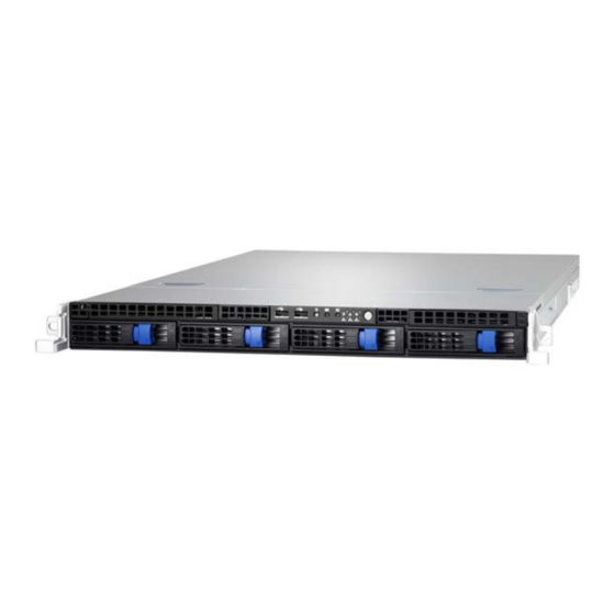
About the Product The following views show you the product. 1.6.1 System Front View System Rear View http://www.tyan.com... -
Page 20: Led Definitions
Description Green 10Mb/100Mb/1000Mb linked RJ-45 Linkage/ Blinking Green 10Mb/100Mb/1000Mb activity Activity(left) No LAN linked Amber 1000Mb linked/activity RJ-45 Linkage/ Green 100Mb linked/activity Activity(Right) 10Mb mode or No LAN linked NOTE: “Left” and “Right” are viewed from the rear panel. http://www.tyan.com... - Page 21 10Mb/100Mb/1000Mb linked RJ-45 Linkage/ Blinking Green 10Mb/100Mb/1000Mb activity Activity(left) No LAN linked Amber 1000Mb linked/activity RJ-45 Linkage/ Green 100Mb linked/activity Activity(Right) 10Mb mode or No LAN linked ID LED State Color Description Blue System identified ID LED System not identified http://www.tyan.com...
-
Page 22: Motherboard (S8212) Layout
1.6.4 Motherboard (S8212) Layout The diagram is representative of the latest board revision available at the time of publishing. The board you receive may not look exactly like the above diagram. http://www.tyan.com... -
Page 23: Jumpers & Connectors
Chassis Intrusion Header IPMB Connector JP19 Onboard VGA Jumper LCM Module Header (Barebones only) 2x10-pin FAN Header (Barebones only) TYAN®-SSI Front Panel Header CPU1_FAN/CPU2_FAN/SYS_FAN1/SYS_FAN2 4-pin FAN Header SYS_FAN3/SYS_FAN4/SYS_FAN5 24-pin EPS12V Power Connector PW2/PW4 8-pin EPS12V Power Connector 4-pin Power Connector... -
Page 24: System Block Diagram
1.6.6 System Block Diagram http://www.tyan.com... -
Page 25: Internal View
1.6.7 Internal View HDD Cage M1232 HDD Backplane System Fans 600W Power Supply Air Duct PCI-E Riser Card Assembly http://www.tyan.com... - Page 26 NOTE http://www.tyan.com...
-
Page 27: Chapter 2: Setting Up
A grounding strap or an anti-static pad Most of the electrical and mechanical connections can be disconnected with your hands. It is recommended that you do not use pliers to remove connectors as it may damage the soft metal or plastic parts of the connectors. http://www.tyan.com... -
Page 28: Precautions
Metallic parts or metal flakes can cause electrical shorts. Note: All connectors are keyed to only attach one way. All use the correct screw size as indicated in the procedures. http://www.tyan.com... -
Page 29: Installing Motherboard Components
CPUs, memory modules and add on cards. 2.1.1 Removing the Chassis Cover Follow these instructions to remove GT24-B8212 chassis cover. Unscrew the rear top cover on the back side as shown in the small diagram. Slide the rear top cover out. http://www.tyan.com... -
Page 30: Installing The Cpu And Heatsink
2.1.2 Installing the CPU and Heatsink Follow the steps below on installing CPUs and CPU heatsinks. Unscrew the air duct to lift it up from the chassis. Locate the CPU socket. Take out the CPU protection cap. http://www.tyan.com... - Page 31 Pull the lever slightly away from the socket and then push it to a fully open position. Push the CPU socket cover to a fully open position. http://www.tyan.com...
- Page 32 Place the CPU into the socket. Close the CPU socket cover and press the lever down to secure the CPU. http://www.tyan.com...
- Page 33 Position the heatsink on top of the CPU and secure it with 2 screws. Repeat the procedures mentioned earlier to install the second CPU and heatsink. http://www.tyan.com...
-
Page 34: Installing The Memory
Align the memory module with the slot. When inserted properly, the memory slot locking levers lock automatically onto the indentations at the ends of the module. Follow the recommended memory population table to install the other memory modules. http://www.tyan.com... - Page 35 http://www.tyan.com...
- Page 36 DIMM’s per CPU). Single CPU Installed Dual CPU Installed (CPU1 only) (CPU1 and CPU2) Population Option CPU1_DIMM0 CPU1_DIMM1 CPU1_DIMM2 CPU1_DIMM3 CPU1_DIMM4 CPU1_DIMM5 CPU1_DIMM6 CPU1_DIMM7 CPU2_DIMM0 CPU2_DIMM1 CPU2_DIMM2 CPU2_DIMM3 CPU2_DIMM4 CPU2_DIMM5 CPU2_DIMM6 CPU2_DIMM7 Note: X indicates a populated DIMM slot. http://www.tyan.com...
-
Page 37: Installing Hard Drives
2.1.4 Installing Hard Drives The GT24-B8212 supports four 3.5” hard drives. Follow these instructions to install a hard drive. Press the locking lever latch and pull the locking lever open. Slide the HDD tray out. Remove the 6 screws. http://www.tyan.com... - Page 38 Place a hard drive into the drive tray. Use 6 HDD screws to secure the HDD. Reinsert the HDD tray into the chassis and press the locking lever to secure the tray. http://www.tyan.com...
-
Page 39: Installing The Pci-E Cards
Pull open the tab of PCI-E slot on the rear panel in the direction as shown to release the PCI bracket. Take out the PCI bracket away from the chassis. Insert the PCI-E card in the direction of arrows as shown. http://www.tyan.com... - Page 40 Close the tab of PCI-E slot to secure PCI-E card. The installation of PCI-E expansion card is now complete. http://www.tyan.com...
-
Page 41: Rack Mounting
Follow these instructions to mount the TYAN GT24-B8212 into an industry standard 19" rack. NOTE: Before mounting the TYAN GT24-B8212 in a rack, ensure that all internal components have been installed and that the unit has been fully tested. Screws List... -
Page 42: Installing The Inner Rails To The Chassis
2.2.2 Installing the inner Rails to the Chassis Screw the mounting ear to each side of TYAN GT24-B8212 as shown using two screws from the supplied screws kit. Draw out the inner rails from rail assembly. Install inner rails to left and right sides of chassis using 1 M4-4L(A) screw for each side. -
Page 43: Installing The Outer Rails To The Rack
Reserve the distance same as in Step 2 on rear bracket. Secure the rear bracket to outer rail with 2 M4-4L(A) screws. Secure the outer rail to the rack using 2 brackets and 4 M5-8L(B) screws for each side. Secure the mounting brackets from inside, not outside, of the rack. http://www.tyan.com... - Page 44 Mounting Bra cket http://www.tyan.com...
-
Page 45: Rack Mounting The Server
Draw out the middle rail to the latch position. Lift the chassis and then insert the inner slide rails into the middle rails. Push the chassis in and press the latch key (A). Then push the whole system into the rack (B) http://www.tyan.com... - Page 46 Secure the mounting ears of chassis to the rack with 2 M5-15L(C) screws. Note: To avoid injury, it is strongly recommended that two people lift the TYAN GT24-B8212 into the place while a third person screws it to the rack. http://www.tyan.com...
-
Page 47: Chapter 3: Replacing Pre-Installed Components
Motherboard, M1008 LED control board, M1232 HDD Backplane, M2091 PCI-E Riser card, System fan, ODD drive, Power supply unit etc. Disassembly Flowchart The following flowchart outlines the disassembly procedure. Rear Components Chassis rear cover DIMMs Power CPU/Heatsink Assembly PCI Card M2091 PCI-E Riser card Mainboard Mainboard http://www.tyan.com... - Page 48 Front Components Chassis rear cover DVD ROM (optional) PCBs M1008 LED M1232 HDD Control Board Backplane http://www.tyan.com...
-
Page 49: Removing The Cover
Unscrew the riser card bracket ( ) and pull it up from the slot ( ) in the direction as shown. Unscrew the M2091 riser card. Install a new riser card onto the bracket following the procedures mentioned earlier in reverse order. http://www.tyan.com... -
Page 50: Disconnecting All Motherboard Cables
3.4.2 Disconnecting All Motherboard Cables Before replacing the motherboard or certain components, remove cables connected to the motherboard. Follow these instructions to remove all motherboard cables. Disconnect all power cables. Disconnect all other cables. http://www.tyan.com... -
Page 51: Removing The Motherboard
After removing all of the aforementioned cables, follow the instructions below to remove the motherboard from the chassis. Remove the heatsinks and processors if installed. Remove the ten screws securing the motherboard to the chassis. Carefully lift the motherboard from the chassis. http://www.tyan.com... -
Page 52: Replacing The Slim Dvd-Rom (Optional)
Follow these instructions to replace the slim DVD-ROM. Remove the power and data cable from the slim DVD-ROM adapter. Press the tab in the directions as shown to release the DVD-ROM drive. The DVD-ROM drive will be freed from the drive bay after pressing the tab. http://www.tyan.com... - Page 53 Disconnect the power and data cables from the DVD-ROM drive. Remove two screws that secure DVD-ROM drive to the bracket. Replace the DVD-ROM drive. Secure DVD-ROM to the bracket using two screws. Then replace the unit into the drive bay and connect the DVD-ROM power and data cables. http://www.tyan.com...
-
Page 54: Replacing The Led Control Board
Follow these instructions to replace the M1008 LED control board. Remove the two screws securing the LED control board unit to the chassis. Push the LED control board unit out and unplug the cables from the connectors at the back of the unit. http://www.tyan.com... - Page 55 Remove three screws securing the LED control board to the bracket. Lift the LED control board free from the chassis. After replacing the LED control board, insert the unit into the chassis following the above procedures in reverse http://www.tyan.com...
-
Page 56: M1008 Led Control Board Features
M1008 LED Control Board Connector Pin Definition J1: USB Header Definition Definition USB1- USB2- USB1+ USB2+ J3: SSI Definition Definition PW_LED+ ID_LED+ PW_LED- ID_LED- HD/LAN3 LED+ SYS_FAULT1- HD/LAN3 LED- SYS_FAULT2- PWR_SW+ LAN1_LED+ PWR_SW- LAN1_LED- RESET+ ICH_SMBDAT RESET- ICH_SMBCLK ID_SW+ INTRU# TEMP_SENSER LAN2_LED+ EXT_INT LAN2_LED- http://www.tyan.com... -
Page 57: Replacing The System Fan
Follow these instructions to replace the cooling fans in your system. Locate the cooling fans in your system. Unplug the cables connected to the mainboard and lift the fan unit up from the chassis. Follow Step A & B to unlock the fans. http://www.tyan.com... - Page 58 40x28mm Fan Step A Step B 40x56mm Fan Step A Step B http://www.tyan.com...
- Page 59 Follow Step C & D to take out the old fan and replace with a new one. Step C Step D 40x28mm Fan 40x56mm Fan http://www.tyan.com...
- Page 60 Reinstall the fans into the chassis. Connect the fan cables to the motherboard fan connectors. System Fan to M1232 System Fan Connect to M1232 → Fan1/Fan6 Fan1 → Fan2/Fan7 Fan2 → Fan3 Fan3 → Fan4 Fan4 → Fan5 Fan5 http://www.tyan.com...
-
Page 61: Replacing The M1232 Hdd Backplane
Replacing the M1232 HDD Backplane Disconnect the power cables connected to the M1232 HDD Backplane. Disconnect the Mini SAS cable and the fan cables. http://www.tyan.com... - Page 62 Remove the three screws securing the bracket to the chassis base. Lift the bracket up from the chassis. Unscrew M1232 board from the bracket. Replace a new M1232 HDD Backplane and reinstall it into the chassis following the above steps in reverse. http://www.tyan.com...
- Page 63 Cable Connect to S8212 MB Board → SAS1 → SAS2 Mini-SAS Cable → SAS3 → SAS4 M1232 SATA/SAS Backplane to S8212G3NR-LE SATA/SAS BP Cable Connect to S8212 MB Board → SATA1 → SATA2 Mini-SAS Cable → SATA3 → SATA4 http://www.tyan.com...
-
Page 64: M1232 Hdd Backplane Features
3.8.1 M1232 HDD Backplane Features Front View J39: Mini SAS Connector http://www.tyan.com... - Page 65 Rear View: LED1 LED2 LED4 LED3 LED6 LED5 LED7 LED8 http://www.tyan.com...
-
Page 66: M1232 Hdd Backplane Connector Pin Definitions
M1232 HDD Backplane Connector Pin Definitions Definition +12V Definition Definition +12V +12V J15 SGPIO JTAG Definition Definition 3.3V J41 SGPIO for IOH Definition Definition SM_CLK SGPIO_0 SM_DATA SGPIO_1 SGPIO_2 SGPIO_3 HD_ERR_LED J5 Slim Hard Disk power Definition +12V J18 Slim CDROM power Definition +12V http://www.tyan.com... - Page 67 Pin 1-2 chose by CPU_PWM (Default) Pin 2-3 chose by CPU_PWM2 LED Definition: Color State Description HDD fail LED Amber SATA/SAS HDD fail (LED 2/4/6/8) No failure found SATA/SAS HDD ready Green Power/Access SATA/SAS HDD Blinking access activity (LED 1/3/5/7) Power disconnected http://www.tyan.com...
-
Page 68: Replacing The Power Supply
Connect to M1232 → 2X2 PIN P7 → BIG 4 PIN P4 600W Power Supply to S8212 Power Supply Connect to S8212 MB → 2X12 PIN P1 → 2X4 PIN P2 → 2X2 PIN P3 → 2X4 PIN P8 http://www.tyan.com... - Page 69 Remove the screws that secure the power supply to the chassis. Take out the power unit and install a new one follow the above steps in reverse. http://www.tyan.com...
- Page 70 NOTE http://www.tyan.com...
-
Page 71: Appendix I: Cable Connection Tables
→ Fan2/Fan7 Fan2 → Fan3 Fan3 → Fan4 Fan4 → Fan5 Fan5 2. SATA HDD Cable M1232 SATA/SAS Backplane to S8212WG3NR-LE SATA/SAS BP Cable Connect to S8212 MB Board → SAS1 → SAS2 Mini-SAS Cable → SAS3 → SAS4 http://www.tyan.com... - Page 72 4. Control Cable and USB Cable M1008 Front Panel Board (FPB) to S8212 M1008 Connect to S8212 → Control Cable → USB Cable USB1 5. FAN Cable M1232 SATA/SAS Backplane to S8212 M1232 Connect to S8212 Fan Control → Cable http://www.tyan.com...
- Page 73 Connect to S8212 MB → 2X12 PIN P1 → 2X4 PIN P2 → 2X2 PIN P3 → 2X4 PIN P8 600W Power Supply to M1232 Power Supply Connect to M1232 → 2X2 PIN P7 → BIG 4 PIN P4 http://www.tyan.com...
- Page 74 NOTE http://www.tyan.com...
-
Page 75: Appendix Ii: Fru Parts Table
Appendix II: FRU Parts Table GT24-B5501 FRU Parts Item Model Number Part Number Picture Quantity Description TYAN S8212WGM3NR-LE S8212WGM3NR-L Motherboard (B8212G24W4H-LE) Motherboard TYAN S8212GM3NR-LE S8212GM3NR-LE Motherboard (B8212G24V4H-LE) Chassis Unit CCHA-0320 432780500001 GT24 Chassis Unit HDD Tray CHDT-0051 340746300001 3.5" HDD Tray... - Page 76 Peripheral Drives & CCBL-032M '422784300007 SATA DVD Data Cable, 400mm Parts (Optional) SATA DVD Power Cable, CCBL-0422 422772300003 110mm NOTE: The table is subject to change without notice. Please visit our Web site at http://www.tyan.com for the latest update. http://www.tyan.com...
-
Page 77: Appendix Iii: Technical Support
Help Resources: 1. See the beep codes section of this manual. 2. See the TYAN’s website for FAQ’s, bulletins, driver updates, and other information: http://www.tyan.com 3. Contact your dealer for help before calling TYAN. 4. Check the TYAN user group: alt.comp.periphs.mainboard.TYAN... - Page 78 -mber. The RMA number should be prominently displayed on the outside of the shipping carton and the package should be mailed prepaid. TYAN will pay to have the board shipped back to you. ® TYAN GT24-B8212 Service Engineer’s Manual V1.00 Document No.:...
Need help?
Do you have a question about the GT24 B8212 and is the answer not in the manual?
Questions and answers