Table of Contents
Advertisement
Quick Links
Advertisement
Table of Contents

Related Manuals for TYAN GC68A-B7136


Summary of Contents for TYAN GC68A-B7136
- Page 1 GC68A-B7136 Service Engineer’s Manual http://www.tyan.com...
- Page 2 MITAC assumes no liability whatsoever, and ® disclaims any express or implied warranty, relating to sale and/or use of TYAN products including liability or warranties relating to fitness for a particular purpose or merchantability. MITAC retains the right to make changes to produce descriptions and/or specifications at any time, without notice.
- Page 3 Notice for Canada This Class A digital apparatus complies with Canadian ICES-003. Cet appareil numérique de la Classe A est conforme à la norme NMB-003 du Canada. Notice for Europe(CE Mark) http://www.tyan.com...
- Page 4 Replace only with the same or equivalent type recommended by manufacturer. Dispose of used battery according to manufacturer instructions and in accordance with your local regulations. Safety: IEC/EN 62368-1 ● This equipment is compliant with CB/LVD of Safety: IEC/EN 62368-1. http://www.tyan.com...
- Page 5 This manual is intended for skilled person with hardware knowledge of computers. Components inside the compartments should be serviced only by a skilled person. This manual is aimed to provide you with instructions on installing your TYAN GC68A-B7136. How this guide is organized...
- Page 6 Safety and Compliance Information Before installing and using TYAN GC68A-B7136, take note of the following precautions: ·Read all instructions carefully. ·Do not place the unit on an unstable surface, cart, or stand. ·Do not block the slots and opening on the unit, which are provided for ventilation.
- Page 7 You must become familiar with the safety information in this guide before you install, operate, or service TYAN products. Symbols on Equipment Caution. This symbol indicates a potential hazard.
- Page 8 · Do not attempt to move a fully loaded rack. Remove equipment from the rack before moving it. · Do not attempt to move a rack on an incline that is greater than 10 degrees http://www.tyan.com...
- Page 9 This will reduce the risk of personal injury, fire, or damage to the equipment. The total rack load should not exceed 80 percent of the branch circuit rating. Consult the electrical authority having jurisdiction over your facility wiring and installation requirements. http://www.tyan.com...
- Page 10 TYAN, your authorized TYAN partner, or their agents. Equipment Modifications · Do not make mechanical modifications to the system. TYAN is not responsible for the regulatory compliance of TYAN equipment that has been http://www.tyan.com...
- Page 11 – The product does not operate normally when you follow the operating instructions. · Retain all screws or other fasteners when removing access cover(s). Upon completion of accessing inside the product, refasten access cover with original screws or fasteners. http://www.tyan.com...
- Page 12 http://www.tyan.com...
-
Page 13: Table Of Contents
Table of Contents Chapter 1: Overview............... 17 About the TYAN GC68A-B7136 ..........17 Product Models ............... 17 Features .................. 18 Standard Parts List ..............23 1.4.1 Box Contents and Accessories ........23 About the Product ..............24 ... - Page 14 USB Configuration ............135 5.3.6 Onboard Device Configuration ........137 5.3.7 Super IO Configuration ..........138 5.3.8 Hardware Health Configuration ........140 5.3.9 PCI Subsystem Settings ..........144 5.3.10 NVMe Configuration ............146 http://www.tyan.com...
- Page 15 Appendix II: Installing IO Rail for OCP Card ......245 Appendix III: Cable Connection Tables ........247 Appendix IV: Fan and Temp Sensors ......... 251 Appendix V: FRU Parts Table ............257 Appendix VI: Technical Support ..........259 http://www.tyan.com...
- Page 16 http://www.tyan.com...
-
Page 17: Chapter 1: Overview
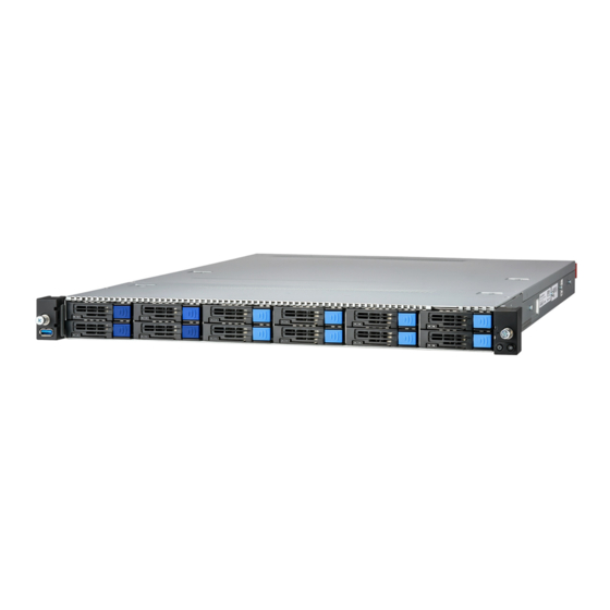
IT demand but also offers a smooth path for future application usage. TYAN® also offers GC68A-B7136 in a version that supports up to (12) hot-swap 2.5" NVMe HDD/SSDs with (4) hot-swap 2.5" SATA 6Gb/s & SAS 12Gb/s. The GC68A-B7136 uses TYAN’s latest chassis featuring a robust structure and a solid... -
Page 18: Features
External Drive Support Notification The SAS/SATA HDD backplane is connected to onboard SATA connection by default. Please contact Tyan technical support if a discrete SAS HBA/RAID adapter is required. System Cooling (1) 4028 fans / (5) 4056 fans Configuration Type... - Page 19 / Boot from USB device/PXE via BIOS LAN/Storage / Console Redirection / SMBIOS 3.3/PnP/Wake on LAN / ACPI 6.0 / ACPI sleeping states S0, S5 Operating OS supported list Please refer to our AVL support lists. System Regulation FCC (SDoC) Class A http://www.tyan.com...
- Page 20 External Drive Support Notification The SAS/SATA HDD backplane is connected to onboard SATA connection by default. Please contact Tyan technical support if a discrete SAS HBA/RAID adapter is required. System Cooling (1) 4028 fans / (5) 4056 fans Configuration Type...
- Page 21 Memory channel 8 Channels per CPU Memory voltage 1.1V PCIe (2) PCI-E Gen.5 x16 slot Pre-installed TYAN Riser (1) M7136G68-L16-1F (1) FH/HL PCIe Gen.5 Expansion Card (PCIe Gen.5) x16 slot (Left) / (1) M7136G68-R16-1F for (1) Slots FH/HL PCIe Gen.5 x16 slot (Right) Others (1) PCI-E Gen.5 x16 OCP 3.0 mezzanine slot...
- Page 22 10° C ~ 35° C (50° F~ 95° F) Operating Non-operating Temp. - 40° C ~ 70° C (-40° F ~ 158° F) Environment In/Non-operating Humidity 90%, non-condensing at 35° C Barebone (1) GC68A-B7136 Barebone Package Contains Manual (1) Quick Installation Guide RoHS RoHS 6/6 Compliant NOTE: 1.
-
Page 23: Standard Parts List
Standard Parts List This section describes GC68A-B7136 package contents and accessories. Open the box carefully and ensure that all components are present and undamaged. The product should arrive packaged as illustrated below. 1.4.1 Box Contents and Accessories If any items are missing or appear damaged, contact your retailer or browse to TYAN’s website for service:... -
Page 24: About The Product
About the Product The following views show you the product. 1.5.1 System Front View Description Description USB3.2 Gen1 Port (M1725G68-USB Power Button with green & red LED pre-installed) Drive Trays ID Button with blue LED http://www.tyan.com... - Page 25 Status LED (Red) Drive present, no activity Green Solid On Drive present with activity Green Blinking Drive Fail Don’t care Red Solid On Drive identify Don’t care Red Blinking @ 1Hz Drive Rebuild Don’t care Red Blinking @ 4Hz http://www.tyan.com...
-
Page 26: System Rear View
2. PCIe Order #2 slot is pre-installed with (1) Riser Card M7136-L16-1L, supports (1) PCIe x16 Gen5 FH/HL @ Slot#6 3. PCIe Gen5 x16 OCP 3.0 Mezz Slot for optional LAN Mezz Card Rear Panel LED Indication Color Behavior ID LED Blue Remote located / Blue Sold On http://www.tyan.com... -
Page 27: Psu And Lan Led Indications
Green Solid On Green Solid On 100 Mbps Active Green Blinking Green Solid On Link Green Solid On Amber Solid On 1000 Mbps (1Gbps) Active Green Blinking Amber Solid On NOTE: “Left” and “Right” are viewed from the rear panel. http://www.tyan.com... -
Page 28: System Top View
System Top View Description Description M1725G68-USB PSU1 (pre-installed) M1724G68-FPB PSU0 (pre-installed) 2.5” SSD/HDD Trays* (1) 4028 + (5) 4056 fans Riser Card Bracket M1631G68-D-85A-PDB-1 (M7136-R16-1F & M7136-L16-1F (pre-installed) pre-installed) *NOTE: M1299G68A-BPE-12 Drive Backplane Board is pre-installed on B7136G68AE12HR-2T / B7136G68AE12HR SKU. http://www.tyan.com... -
Page 29: Chassis Dimensions
1.5.5 Chassis Dimensions http://www.tyan.com... - Page 30 NOTE http://www.tyan.com...
-
Page 31: Chapter 2: Setting Up
Caution! To avoid damaging the motherboard and associated components, use torque force within the range kgf/cm (4.35 ~ 6.09 lb/in) on each mounting screw for motherboard installation. Do not apply power to the board if it has been damaged. http://www.tyan.com... -
Page 32: Precautions
Working on a system that is connected to a power supply can be extremely dangerous. Follow the guidelines below to avoid damage to GC68A-B7136 or injury to yourself. Ground yourself properly before removing the top cover of the system. -
Page 33: Installing Motherboard Components
CPUs, memory modules and add-on cards. 2.1.1 Removing the Chassis Cover Follow these instructions to remove the GC68A-B7136 chassis cover. 1. Use a screw driver to loosen the captive screw. 2. Pull up the latch and slide it backwards. http://www.tyan.com... - Page 34 3. Slide to lift up the rear top cover. 4. Unscrew the front top cover and then slide it forwards to lift it up. http://www.tyan.com...
- Page 35 http://www.tyan.com...
-
Page 36: Replacing The Chassis Cover
2.1.2 Replacing the Chassis Cover Follow these instructions to replace the GC68A-B7136 chassis cover. 1. Place the front top cover on the chassis and slide it backwards. Secure the front top cover with two screws. http://www.tyan.com... - Page 37 2. Place the rear top cover on the chassis and slide it forwards. 3. Adjust the power clips. 4. Use a screw driver to fasten the captive screw on the rear top cover. http://www.tyan.com...
-
Page 38: Installing The Cpu, Heatsink And Air Duct
Installing the CPU, Heatsink and Air Duct Follow the steps below to install the CPU, heatsink and air duct. The GC68A-B7136 supports (2) Intel® Xeon® Eagle Stream (Sapphire Rapids-SP) series CPU. The following installation is based on an Intel LGA4677 socket. - Page 39 4. Align the triangle edge of the carrier with the notch on the edge of the heatsink. Then install the carrier on the bottom of the heatsink and make sure the latches are snapped under the edge of the heatsink. http://www.tyan.com...
- Page 40 6. Align the heatsink with the CPU socket by the guide pins. Make also sure that the triangle edge of the carrier is aligned correctly with the triangle mark on the CPU socket. Then place the heatsink assembly onto the top of the CPU socket. http://www.tyan.com...
- Page 41 7. Press down on the retention clips to fix the heatsink assembly to the CPU socket. 8. To secure the heatsink assembly, use a T30 Security Torx to tighten the screws in a sequential order (1234). NOTE: When dissembling the heatsink, loosen the screws in reverse order (4321). http://www.tyan.com...
- Page 42 NOTE: A new heatsink comes with pre-installed thermal grease. Once the heatsink has been removed from the processor, you need to clean the processor and heatsink using an alcohol solvent. Then apply new thermal grease before reinstalling the heatsink. http://www.tyan.com...
-
Page 43: Installing The Memory
2.1.4 Installing the Memory Follow these instructions to install the memory modules onto the motherboard. Unlock the clips. Insert the memory module. Lock the clips. http://www.tyan.com... - Page 44 Memory Population table http://www.tyan.com...
- Page 45 CHG_DIM0, P0_ CHH_DIM0. or P0_CHB_DIM0, P0_ CHC_DIM0, P0_ CHD_DIM0,P0_ CHE_DIM0, P0_ CHF_DIM0, P0_ CHH_DIM0. P0_CHA_DIM0, P0_ CHB_DIM0, P0_ CHD_DIM0,P0_ CHF_DIM0, P0_ CHG_DIM0, P0_ CHH_DIM0 DIMMs: P0_ CHA_DIM0, P0_ CHB_DIM0, P0_ CHC_DIM0, P0_ CHD_DIM0, P0_ CHE_DIM0, P0_ CHF_DIM0, P0_ CHG_DIM0, P0_ CHH_DIM0. http://www.tyan.com...
- Page 46 √ √ √ √ √ P1_CHD_DIM0 √ √ √ √ √ P1_CHE_DIM0 √ √ √ √ √ √ P1_CHF_DIM0 √ √ √ √ √ P1_CHG_DIM0 √ √ √ √ √ √ P1_CHH_DIM0 √ √ √ √ http://www.tyan.com...
-
Page 47: Installing The Expansion Card
2.1.5 Installing the Expansion Card Follow these instructions to install the expansion card. Loosen three screws to take out the riser card bracket. Unscrew to remove the dummy bracket. http://www.tyan.com... - Page 48 Insert the expansion card into the riser card bracket and secure with a screw. Replace the Riser Card Bracket into the chassis. http://www.tyan.com...
-
Page 49: Installing The 2.5" Hard Drive
Follow these instructions to install the 2.5” hard drives for B7136G68AV4E8HR-2T / B7136G68AV4E8HR SKU. 1. Press the locking tab to pull the lever open. 2. Slide the drive tray out. 3. Press the locking tab to pull the tray side rail open. http://www.tyan.com... - Page 50 4. Align the hard drive with the guide pins and install the hard drive into the drive tray. Close the tray side rail. http://www.tyan.com...
- Page 51 5. Insert the drive tray into the chassis and close the lever. http://www.tyan.com...
-
Page 52: Installing The M.2 Card
Follow these instructions to install the M.2 Card. 1. Take out the M.2 Latch from the AK box. 2. Insert the M.2 latch into the M.2 latch screw hole. 3. Insert the M.2 card into the slot. Close the latch to lock the M.2 card. http://www.tyan.com... - Page 53 4. Insert the second M.2 card into the slot. Pull the latch as shown to lock the M.2 card. http://www.tyan.com...
-
Page 54: Rack Mounting
Rails x 2 Screw Sacks x 2 2.2.1 Installing the Server in a Rack Follow these instructions to mount the GC68A-B7136 into an industry standard 19” rack. Note: Before mounting GC68A-B7136 in a rack, ensure that all internal components have been installed and that the unit has been fully tested. -
Page 55: Installing Slide Rails To The Rack
Take out the rails from the accessory kit. Push the white tab in the direction as the arrow shows to draw out the inner rail. Attach the inner rails to both sides of the chassis. Push the inner rails backward to lock in place. http://www.tyan.com... - Page 56 Attach the outer rail to the rack. Pull the latch open and align the square stud with the square hole on the rack rail. Please note that the square stud must be fully attached inside the square hole and then close the latch to lock. Rear http://www.tyan.com...
- Page 57 Front http://www.tyan.com...
-
Page 58: Rack Mounting The Server
Must be done with at least 2 people. Properly place the chassis directly on the rack and install. Slide in the chassis half way to the lock position. Push the blue tabs simultaneously to slide the chassis all in. http://www.tyan.com... - Page 59 Fasten the chassis ear to the front surface of chassis. http://www.tyan.com...
-
Page 60: Removing The Server From Rack
Pull out the chassis half way to the lock position. Push the white locking tabs forward to slide the chassis all out from the rack. Caution: Remove the server from the rack carefully. Must be done with at least 2 people. http://www.tyan.com... -
Page 61: Chapter 3: Replacing Pre-Installed Components
This chapter explains how to replace the pre-installed components, including the S7136 Motherboard, M1724G68-FPB Front Panel Board, M1725G68-USB Front USB Board, M7136-L16-1F M7136-R16-1F Riser Cards, M1299GC68A-BPE-12 HDD Backplane Board, M1631G68-D-85A-PDB Power Distribution Board, System Fan and Power Supply etc. Disassembly Flowchart The following flowchart outlines the disassembly procedure. http://www.tyan.com... -
Page 62: Removing The Cover
Removing the Cover Follow Chapter 2.1.1 to remove the cover of GC68A-B7136. Replacing the Power Supply To replace the power supply follow these instructions. 1. Press the latch as shown to pull out the power supply module. 2. Replace a new single power and reinsert it into the power cage following the above steps in reverse. -
Page 63: Replacing The Front Panel Board
2. Loosen 2 screws to remove the front panel cage and bracket. 3. Disconnect the cable and unscrew the Front Panel Board. 4. After replacing with a new Front Panel Board, follow the steps described earlier in reverse order to reinstall the front panel bezel. http://www.tyan.com... -
Page 64: Front Panel Board Features
3.5.1 Front Panel Board Features Front View Rear View M1724G68-FPB Front Panel Board Form Factor 33.5*21*1.6 mm (1) Signal Connector (J1) Integrated I/O (1) PWR Button (1) ID Button http://www.tyan.com... -
Page 65: Replacing The Usb Board
2. Loosen 2 screws to remove the USB cage and bracket. 3. Disconnect the cable and unscrew the USB Board. 4. After replacing with a new USB Board, follow the steps described earlier in reverse order to reinstall the front USB bezel. http://www.tyan.com... -
Page 66: Usb Board Features
3.6.1 USB Board Features Front View Rear View M1725G68-USB Front Panel Board Form Factor 31.9*19.4*1.6 mm (1) Signal Connector (J2) Integrated I/O (1) USB3.0 Connector http://www.tyan.com... -
Page 67: Replacing The Hdd Backplane Board
HDD Backplane Board. 2. Use a screwdriver to unscrew the M1299G68A-BPE-12 HDD Backplane Board. 3. After replacing with a new HDD Backplane Board, follow the procedures described earlier in reverse order to reinsert the HDD Backplane Board into the chassis. http://www.tyan.com... -
Page 68: Hdd Bp Board Features
435*38.3*2.6 mm PCI-E Gen4 12-pot NVMe U.2 BP Board (12) Hot-swap 2.5” NVMe U.2 SSD (2) ATX 2x4-pin Power Connector Integrated I/O (2) 5V connector for DOM (6) Slim-SAS connector (8) Fan connector (1) 2x15-pin Fan Control Connector (J31) http://www.tyan.com... -
Page 69: Replacing Power Distribution Board
1. Pull the power supply modules slightly away from the chassis. Release cable ties and disconnect all cables from the Power Distribution Board. 2. Unscrew to replace the M1631G68-D-85A-PDB Power Distribution Board. 3. Follow the steps described earlier in reverse order to reinstall the power distribution board into the chassis. http://www.tyan.com... -
Page 70: Power Distribution Board Features
3.8.1 Power Distribution Board Features M1631G68-D-85A-PDB Power Distribution Board Form Factor 171*108*1.6 mm (1) ATX24P (2) ATX8P (1) HDD 4P PWR Specifications (2) DOM 5V PWR (1) PMBUS (2) Micro ATX8P http://www.tyan.com... -
Page 71: Connector Definitions
3.8.2 Connector Definitions Location Definition Power supply slot Power supply slot PWR1 ATX Power 12x2 ATX Power 4x2 ATX Power 4x2 HDD Power 4x1 Micro ATX Power 4x2 Micro ATX Power 4x2 PMBUS DOM_5V_PW1 DOM Power DOM_5V_PW2 DOM Power http://www.tyan.com... -
Page 72: Replacing The Riser Card
1. Lift up the Riser Card Bracket from the chassis. Unscrew to replace with a new riser card M7136G68-L16-1F. 2. Unscrew to replace with a new riser card M7136G68-R16-1F. 3. Follow the steps described earlier in reverse order to reinstall the riser card bracket into the chassis. http://www.tyan.com... -
Page 73: Riser Card Features
PCI-E x16 Gen5 adapter card Specification (1) PCI-E x16 Gen5 slot support (1) PCI-E x16 Add-on card M7136G68-R16-1F Riser Card Form Factor W1.26” x D4.88”(W32mmxD124mm) PCI-E x16 Gen5 adapter card Specification (1) PCI-E x16 Gen5 slot support (1) PCI-E x16 Add-on card http://www.tyan.com... -
Page 74: Replacing The Fan
1. Disconnect the fan PWR cable. 2. Lift up the fan module from the chassis. 3. Release the rubber screws and push pins from the fan module. Replace with a new fan and then insert the rubber screws and push pins. http://www.tyan.com... - Page 75 4. Place the new fan module into the chassis and reconnect the fan cable. Remember to tie cables after fan replacement. http://www.tyan.com...
-
Page 76: Replacing The Motherboard
After removing all of the aforementioned components, follow these instructions to remove the motherboard from the chassis. Release the cable tie and disconnect all cables connected to the mainboard. Remove ten screws securing the motherboard to the chassis. Carefully remove the motherboard from the chassis for replacement. http://www.tyan.com... -
Page 77: Chapter 4: Mainboard Information
To avoid damaging the motherboard and associated components, do not use torque force greater than kgf/cm (4.35 ~ 6.09 lb/in) on each mounting screw for motherboard installation. Do not apply power to the board if it has been damaged. http://www.tyan.com... -
Page 78: Board Image
Board Image S7136GMRE This picture is representative of the latest board revision available at the time of publishing. The board you receive may not look exactly like the above picture. http://www.tyan.com... - Page 79 S7136GM2NRE-2T This picture is representative of the latest board revision available at the time of publishing. The board you receive may not look exactly like the above picture. http://www.tyan.com...
-
Page 80: Block Diagram
Block Diagram S7136 Block Diagram http://www.tyan.com... -
Page 81: Mainboard Mechanical Drawing
Mainboard Mechanical Drawing http://www.tyan.com... -
Page 82: Board Parts, Jumpers And Connectors
The board you receive may not look exactly like the above diagram. But for the DIMM number please refer to the above placement for memory installation. For the latest board revision, please visit our web site at http://www.tyan.com. http://www.tyan.com... - Page 83 40 4-pin 12V Power Connector (PWR4 (J1_OCP3)) (J55)) 18 PCH_SAT_RAID_KEY (RAID KEY 41 24-pin ATX Power Connector (J51)) (PWR1) 19 8-pin CPU1 Power Connector 42 PSMI Pin Header (PSMI_HD1) (PWR3 (PW2)) 20 Vertical MCIO Connector (MCIO8 43 FPB USB2.0 / USB3.2 Gen1 http://www.tyan.com...
- Page 84 On board BMC IPMI Alert LED BMC Heartbeat LED (BMC_LED (IPMI_LED1) (D1_BMC)) Platform RESET LED VIII Rear ID LED (ID_LED (ID_LED1)) (PLTRST_LED (D83)) Jumper Legend OPEN - Jumper OFF Without jumper cover CLOSED - Jumper ON With jumper cover http://www.tyan.com...
- Page 85 FP_PW_LED_PW FP_ PWER (P3V3_AUX) FP_ID_LED_PW FP_PW_LED_GND FP_ID_LED_N HDD_LED_PW BMC_HW_FAULT_N HDD_ACT_LED_N BMC_SYS_FAULT_N FP_PWR_BTN_N LAN0_LED_P LAN0_LED_N FP_RST_BTN_JP_N FP_SMB_DAT FP_SMB_CLK FP_IDLED_BTN_N FP_INTRUSION_N SYS_AIR_INLET LAN1_LED_P FP_NMI_BTN_N LAN1_LED_N PSMI_HD1: PSMI Connector Signal SMB_CLK SMB_DAT PSU_SMBALERT_N P3V3 IPMB_HD1: 4-pin IPMB Connector Signal IPMB_DAT IPMB_CLK P3V3_AUX http://www.tyan.com...
- Page 86 USB3_FPIO1: Front USB3.2 Gen1 Header Signal Signal USB3_N1_RX_FPB USB3_P1_RX_FPB USB3_N0_RX_FPB USB3_P0_RX_FPB USB3_N1_TX_C_FPB USB3_P1_TX_C_FPB USB3_N0_TX_C_FPB USB3_P0_TX_C_FPB USB2_FRONT2_R_DN USB2_FRONT2_R_DP USB2_FRONT_R_DN OC_N USB2_FRONT_R_DP J51: Intel ® VROC RAID KEY Connector (NVMe only) Pin1 Pin2 Pin3 Pin4 2.21K to 2.21K to VCC3_AUX VCC3_AUX http://www.tyan.com...
- Page 87 P3V3_AUX HD_COM2: COM Port Header Signal Signal COM2_DCD COM2_DSR COM2_RXD COM2_RTS COM2_TXD COM2_CTS COM2_DTR COM2_NRI HDR_3 (CPU_HP_SMBUS): 7-pin NVMe Hot Plug Function Connector Signal P3V3_AUX HP0_SCK HP0_SDA CPU01_SMBALERT_N HP1_SCK HP1_SDA IDLED_BTN1: Rear IO ID LED Button Signal Signal FP_IDLED_BTN_N http://www.tyan.com...
- Page 88 Enter BIOS setup menu and load Default Settings. Then do a Save and Exit from setup. TYPEA_USB2: 4-pin Vertical USB2.0 Connector Signal USB2_N8 USB2_P8 SATA4: 7-pin Vertical SATA Connector PIN Define SATA8_TXP_C Connects to the Serial SATA8_TXN_C ATA ready drives via the Serial ATA cable. SATA8_RXN_C SATA8_RXP_C http://www.tyan.com...
- Page 89 RMII_RXD<1> RMII_TXD<0> RMII_RXD<0> OA10 OB10 CLK_100M_DN<3> OA11 OB11 CLK_100M_DN<2> CLK_100M_DP<3> OA12 OB12 CLK_100M_DP<2> OA13 OB13 RMII_CLK_IN OA14 OB14 RMII_CRS_DV P12V_EDGE_F P12V_EDGE_F P12V_EDGE_F P12V_EDGE_F P12V_EDGE_F P12V_EDGE_F SMB_SCL BIF_L<0> SMB_SDA BIF_L<1> SMB_RST_L BIF_L<2> PRSNTA1_N RST_PERST0_L RST_PERST1_L P3V3_EDGE_F PRSNTB2_L AUX_PWR_EN CLK_100M_DN<1> CLK_100M_DN<0> http://www.tyan.com...
- Page 90 PE_HOST_OCP_TX_DN<9> PE_HOST_OCP_RX_DP<9> PE_HOST_OCP_TX_DP<9> PE_HOST_OCP_RX_DN<8> PE_HOST_OCP_TX_DN<8> PE_HOST_OCP_RX_DP<8> PE_HOST_OCP_TX_DP<8> PRSNTB1_L PRSNTB0_L PE_HOST_OCP_RX_DN<7> PE_HOST_OCP_TX_DN<7> PE_HOST_OCP_RX_DP<7> PE_HOST_OCP_TX_DP<7> PE_HOST_OCP_RX_DN<6> PE_HOST_OCP_TX_DN<6> PE_HOST_OCP_RX_DP<6> PE_HOST_OCP_TX_DP<6> PE_HOST_OCP_RX_DN<5> PE_HOST_OCP_TX_DN<5> PE_HOST_OCP_RX_DP<5> PE_HOST_OCP_TX_DP<5> PE_HOST_OCP_RX_DN<4> PE_HOST_OCP_TX_DN<4> PE_HOST_OCP_RX_DP<4> PE_HOST_OCP_TX_DP<4> PE_HOST_OCP_RX_DN<3> PE_HOST_OCP_TX_DN<3> PE_HOST_OCP_RX_DP<3> PE_HOST_OCP_TX_DP<3> PE_HOST_OCP_RX_DN<2> PE_HOST_OCP_TX_DN<2> PE_HOST_OCP_RX_DP<2> PE_HOST_OCP_TX_DP<2> PE_HOST_OCP_RX_DN<1> PE_HOST_OCP_TX_DN<1> PE_HOST_OCP_RX_DP<1> PE_HOST_OCP_TX_DP<1> PE_HOST_OCP_RX_DN<0> PE_HOST_OCP_TX_DN<0> http://www.tyan.com...
- Page 91 M2_CN1, M2_CN2: M.2 Connector Signal Signal P3V3 P3V3 CPU0_PE3_M2_RX_R_DN<7> CPU0_PE3_M2_RX_R_DP<7> P3V3_AUX M2_LED_N CPU0_PE3_M2_TX_C_DN<7> P3V3 CPU0_PE3_M2_TX_C_DP<7> P3V3 P3V3 CPU0_PE3_M2_RX_R_DN<6> P3V3 CPU0_PE3_M2_RX_R_DP<6> CPU0_PE3_M2_TX_C_DN<6> CPU0_PE3_M2_TX_C_DP<6> CPU0_PE3_M2_RX_R_DN<5> CPU0_PE3_M2_RX_R_DP<5> CPU0_PE3_M2_TX_C_DN<5> CPU0_PE3_M2_TX_C_DP<5> M2_SMB_CLK CPU0_PE3_M2_RX_R_DN<4> M2_SMB_DAT CPU0_PE3_M2_RX_R_DP<4> M2_SMB_ALERT_N CPU0_PE3_M2_TX_C_DN<4> CPU0_PE3_M2_TX_C_DP<4> M2_PERST_N CLK_100M_M2_DN M2_WAKE_PCIE_N CLK_100M_M2_DP SATA_PCIE_M2_SEL P3V3 P3V3 P3V3 http://www.tyan.com...
- Page 92 RST_NVME1_CPU0_PERST CLK_100M_CPU0_NVME_ CPRSNTA CPU0_PE0_RX_DP<2> CPU0_PE0_TX_DP<2> CPU0_PE0_RX_DN<2> CPU0_PE0_TX_DN<2> CPU0_PE0_RX_DP<3> CPU0_PE0_TX_DP<3> CPU0_PE0_RX_DN<3> CPU0_PE0_TX_DN<3> SATA_0_3: 36-pin Vertical Mini SAS HD Connector (SATA 3.0 signals) Signal Signal PCH_SSATA_0-3_A1 SGPIO_SATA2_CLOCK_R SGPIO_SATA2_LOAD_R SATA6G_DMI_RX_C_DP<5> SATA6G_DMI_RX_C_DP<4> SATA6G_DMI_RX_C_DN<5> SATA6G_DMI_RX_C_DN<4> SATA6G_DMI_RX_C_DP<7> SATA6G_DMI_RX_C_DP<6> SATA6G_DMI_RX_C_DN<7> SATA6G_DMI_RX_C_DN<6> SGPIO_SATA2_DATOUT_R SSGPIO_DI_0R SAS1_CTYPE SATA6G_DMI_TX_C_DP<5> SATA6G_DMI_TX_C_DP<4> http://www.tyan.com...
- Page 93 SATA1_RXN_C SATA0_RXN_C SATA3_RXP_C SATA2_RXP_C SATA3_RXN_C SATA2_RXN_C SGPIO_SATA0_DATOUT_R SGPIO_DI_0R SAS0_CTYPE SATA1_TXP_C SATA0_TXP_C SATA1_TXN_C SATA0_TXN_C SATA3_TXP_C SATA2_TXP_C SATA3_TXN_C SATA2_TXN_C NC_PCH_SATA_0-7_A1 SGPIO_SATA1_CLOCK_R SGPIO_SATA1_LOAD_R SATA5_RXP_C SATA4_RXP_C SATA5_RXN_C SATA4_RXN_C SATA7_RXP_C SATA6_RXP_C SATA7_RXN_C SATA6_RXN_C SGPIO_SATA1_DATOUT_R SGPIO_DI_1R SAS1_CTYPE SATA5_TXP_C SATA4_TXP_C SATA5_TXN_C SATA4_TXN_C SATA7_TXP_C SATA6_TXP_C SATA7_TXN_C SATA6_TXN_C http://www.tyan.com...
- Page 94 J2_PCH: PASSWORD CLEAR Jumper Pin1 Pin2 Pin3 FM_PASSWORD_CLEAR_N 1K-Pull down Pin1-2 closed: Normal Mode (Default) Pin2-3 closed: PASSWORD CLEAR J3_PCH: ME Recovery Jumper Pin1 Pin2 Pin3 10K-Pull hi FM_ME_RCVR_N 1K-Pull down Pin1-2 closed: Normal Mode (Default) Pin2-3 closed: Recover ME http://www.tyan.com...
- Page 95 Pin1-2 closed: Enable BMC Remote Debug Pin2-3 closed: Disable BMC Remote Debug (Default) J136: System Reset Jumper Pin1 Pin2 Pin3 FP_RST_BTN_N FP_RST_BTN_JP_N FP_BMC_RST_BTN_N Pin1-2 closed: System Reset (Default) Pin2-3 closed: BMC Reset 3PHD8: SMBUS Select Header (reserved) Pin1 Pin2 Pin3 CPU#_BMC_SMB_SEL http://www.tyan.com...
- Page 96 J14: System Buzzer Jumper Pin1 Pin2 Pin3 Pin4 VCC5_BZ BUZ_1 BUZ_2 Pin3-4 closed: Normal Mode (Default) Pin2-3 closed: Disable PC Beep Pin1-4 closed: Use the external speaker http://www.tyan.com...
-
Page 97: Led Definitions
P3V3_STBY State Description BMC_LED The LED shuts off when the BMC Heartbeat (D1_BMC) controller cannot be detected or properly initiated The LED blinks per second to Blinking Green indicate that the BMC controller is working normally CPLD_LED CPLD Signal http://www.tyan.com... - Page 98 State Description (D83) Platform Reset LED status is normal Platform Reset LED status is abnormal Signal P3V3 SYS_PWROK System State Description LED (D82) Power ok LED System Power LED status is normal System Power LED status is abnormal http://www.tyan.com...
-
Page 99: Installing The Processor And Heat Sink
錯誤! 尚未定義書籤。. Check our website at for latest processor support. NOTE: MITAC TYAN is not liable for damage as a result of operating an unsupported configuration. Processor Installation for Intel LGA4677 Socket Follow the steps below to install the processors and heat sinks. - Page 100 2. Align and install the processor on the carrier. Make sure the gold arrow is located in the correct direction. NOTE: When installing the processor, secure the front side (A) first, and following with the middle and rear sides (BC). 3. Remove the CPU cover. http://www.tyan.com...
- Page 101 Make also sure that the triangle edge of the carrier is aligned correctly with the triangle mark on the CPU socket. Then place the heatsink assembly onto the top of the CPU socket. 5. Press down on the retention clips to fix the heatsink assembly to the CPU socket. http://www.tyan.com...
- Page 102 Then apply new thermal grease before reinstalling the heatsink. NOTE: Always check with the manufacturer of the heat sink & processor to ensure that the thermal interface material is compatible with the processor and meets the manufacturer’s warranty requirements. http://www.tyan.com...
-
Page 103: Tips On Installing Motherboard In Chassis
Some chassis include plastic studs instead of metal. Although the plastic studs are usable, MITAC recommends using metal studs with screws that will fasten the motherboard more securely in place. Below is a chart detailing what the most common motherboard studs look like and how they should be installed. http://www.tyan.com... - Page 104 http://www.tyan.com...
-
Page 105: Installing The Memory
Installing the Memory Before installing memory, ensure that the memory you have is compatible with the motherboard and processor. Check the TYAN Web site at http://www.tyan.com details of the type of memory recommended for your motherboard. Supports up to 128GB of ECC UDIMM DDR4 2666/2400MHz memory. - Page 106 CHG_DIM0, P0_ CHH_DIM0. or P0_CHB_DIM0, P0_ CHC_DIM0, P0_ CHD_DIM0,P0_ CHE_DIM0, P0_ CHF_DIM0, P0_ CHH_DIM0. P0_CHA_DIM0, P0_ CHB_DIM0, P0_ CHD_DIM0,P0_ CHF_DIM0, P0_ CHG_DIM0, P0_ CHH_DIM0 DIMMs: P0_ CHA_DIM0, P0_ CHB_DIM0, P0_ CHC_DIM0, P0_ CHD_DIM0, P0_ CHE_DIM0, P0_ CHF_DIM0, P0_ CHG_DIM0, P0_ CHH_DIM0. http://www.tyan.com...
- Page 107 √ √ √ √ √ √ P1_CHD_DIM0 √ √ √ √ √ P1_CHE_DIM0 √ √ √ √ √ √ P1_CHF_DIM0 √ √ √ √ √ P1_CHG_DIM0 √ √ √ √ √ √ P1_CHH_DIM0 √ √ √ √ http://www.tyan.com...
- Page 108 Follow these instructions to install memory modules into the S7136. Unlock the clips as shown in the illustration. Insert the memory module firmly into the socket by gently pressing down until it sits flush with the socket. Lock the clips to secure the memory module into place. http://www.tyan.com...
-
Page 109: Attaching Drive Cables
If you are in need of SATA/SAS cables or power adapters please contact your place of purchase. The following pictures illustrate how to connect an SATA drive. 1. SATA drive cable connection 2. SATA drive power connection 3. SATA cable motherboard connector 4. SATA drive power adapter http://www.tyan.com... -
Page 110: Installing Add-In Cards
Doing so allows air to circulate within the chassis more easily, thus improving cooling for all installed devices. NOTE: You must always unplug the power connector to the motherboard before performing system hardware changes to avoid damaging the board or expansion device. http://www.tyan.com... -
Page 111: Connecting External Devices
No Link Link Solid Green Linked at 10Mbps Active Blinking Green Link Solid Green Solid Green Linked at 100 Mbps Active Blinking Green Solid Green Link Solid Green Solid Amber Linked at 1 Gbps Active Blinking Green Solid Amber http://www.tyan.com... - Page 112 Active Blinking Yellow Link Solid Green Solid Yellow 1/2.5/5 Gbps Active Blinking Green Solid Yellow Link Solid Yellow Solid Yellow 10 Gbps Active Blinking Yellow Solid Yellow NOTE: Right LED (Speed) is a single-color LED, always showing yellow color. http://www.tyan.com...
-
Page 113: Installing The Power Supply
PWR1: ATX 24-pin Main Power Connector Signal Signal P3V3 P3V3 P3V3 VCC12N FM_PS_EN_PSU_N PRRGD_PS_PWROK P5V_STBY 12V_IN 12V_IN P3V3 PW1 (PWR2): 8-PIN CPU0 Power Connector Signal Signal VCC12_P0_CPU VCC12_P0_CPU VCC12_P0_CPU VCC12_P0_CPU PW2 (PWR3): 8-PIN CPU1 Power Connector Signal Signal VCC12_P1_CPU VCC12_P1_CPU VCC12_P1_CPU VCC12_P1_CPU http://www.tyan.com... - Page 114 J55 (PWR4): 4-Pin Power Connector Signal Signal VCC12_CPU_OTHERS VCC12_CPU_OTHERS http://www.tyan.com...
-
Page 115: Installing Ocp3.0 Rail Kit
2. Install the OCP rail to the chassis. Then secure the rail using 1 screw. 2. Insert the server board into the chassis. 3. Use 9 screws (blue arrow) to secure the server board to the chassis. Then use another screw (red arrow) to secure the server board to OCP rail. http://www.tyan.com... -
Page 116: Finishing Up
In the rare circumstance that you have experienced difficulty, you can find help by asking your vendor for assistance. If they are not available for assistance, please find setup information and documentation online at our website or by calling your vendor’s support line. http://www.tyan.com... -
Page 117: Chapter 5: Bios Setup
The table below shows how to navigate in the setup program using the keyboard. Function Left/Right Arrow Keys Change from one menu to the next Up/Down Arrow Keys Move between selections Enter Open highlighted section PgUp/PgDn Keys Change pages Change options Exit http://www.tyan.com... -
Page 118: Getting Help
The following pages provide the details of BIOS menu. Please be noticed that the BIOS menu are continually changing due to the BIOS updating. The BIOS menu provided are the most updated ones when this manual is written. Please visit TYAN’s website at http://www.tyan.com for the information of BIOS updating. -
Page 119: Main Menu
System Date Set the Date. Use Tab to switch between Date elements. Default Ranges: Year: 2010~2079 Months: 1-12 Days: dependent on month Range of Years may vary. System Time Set the Time. Use Tab to switch between Time elements. http://www.tyan.com... -
Page 120: Advanced Menu
S5 RTC Wake Settings Enable system to wake from S5 using RTC alarm. Serial Port Console Redirection Serial Port Console Redirection. PCIe Device Configuration PCIe Device Configuration. USB Configuration USB Configuration Parameters. Onboard Device Configuration Onboard Device and Function Configuration. http://www.tyan.com... - Page 121 TIs Auth Configuration Press <Enter> to select TIs Auth Configuration. VLAN Configuration (MAC: XXXXXXXXXXXX) VLAN Configuration (MAC: XXXXXXXXXXXX) MAC: XXXXXXXXXXXX --- IPV4 Network Configuration Configure network parameters. (MAC: XXXXXXXXXXXX) MAC: XXXXXXXXXXXX --- IPV6 Network Configuration Configure IPV6 network parameters. (MAC: XXXXXXXXXXXX) http://www.tyan.com...
-
Page 122: Network Stack Configuration
Enable Ipv4 HTTP Boot Support. If disabled IPV4 HTTP boot option will not be available. Disabled / Enabled Ipv6 PXE Support Enable Ipv6 PXE Boot Support. If disabled IPV6 PXE boot option will not be available. Disabled / Enabled http://www.tyan.com... - Page 123 Disabled / Enabled PXE boot wait time Wait time to press ESC key to abort the PXE boot. Media detect count Number of times the presence of media will be checked. Use either +/- or numeric keys to set the value. http://www.tyan.com...
-
Page 124: S5 Rtc Wake Settings
Select 0-23. For example enter 3 for 3am and 15 for 3pm. Wake up minute Select 0-59 for Minute. Wake up second Select 0-59 for Second. When Wake system from S5 is set to [Dynamic Time] Wake up Minute increase 1-5. http://www.tyan.com... -
Page 125: Serial Port Console Redirection
Console redirection enable or disable. Disabled / Enabled Legacy Console Redirection Settings Legacy Console redirection settings. Console Redirection Settings The settings specify how the host computer (which the user is using) will exchange data. Both computers should have the same or compatible settings. http://www.tyan.com... - Page 126 0 if the num of 1’s in the data bits is even. Odd: parity bit is 0 if the num of 1’s in the data bits is odd. Mark: parity bit is always 1. Space: parity bit is always 0. Mark and Space parity do not allow for error detection. None / Even / Odd / Mark / Space http://www.tyan.com...
- Page 127 On this mode enabled only text will be sent. This is to capture Terminal data. Disabled / Enabled Resolution 100x31 Enable or disable extended terminal resolution. Disabled / Enabled Putty KeyPad Select FunctionKey and KeyPad on Putty. VT100 / LINUX / XTERMR6 / SCO / ESCN / VT400 http://www.tyan.com...
- Page 128 0 if the num of 1’s in the data bits is even. Odd: parity bit is 0 if the num of 1’s in the data bits is odd. Mark: parity bit is always 1. Space: parity bit is always 0. Mark and Space parity do not allow for error detection. None / Even / Odd / Mark / Space http://www.tyan.com...
- Page 129 On this mode enabled only text will be sent. This is to capture Terminal data. Disabled / Enabled Resolution 100x31 Enable or disable extended terminal resolution. Disabled / Enabled Putty KeyPad Select FunctionKey and KeyPad on Putty. VT100 / LINUX / XTERMR6 / SCO / ESCN / VT400 http://www.tyan.com...
- Page 130 When BootLoader is selected, then Legacy Console Redirection is disabled before booting to legacy OS, When Always Enable is selected, then Legacy Console Redirection is enabled for legacy OS. Default setting for this option is set to Always Enable. Always Enable / BootLoader http://www.tyan.com...
- Page 131 VT-UTF8 / VT100 / VT100+ / ANSI Bits per Second Select serial port transmission speed. The speed must be matched on the other side. Long or noisy lines may require lower speeds. 115200 / 9600 / 19200 / 57600 http://www.tyan.com...
- Page 132 ‘start’ signal can be sent to restart the flow. Hardware flow control uses two wires to send start/stop signal. None / Hardware RTS/CTS / Software Xon/Xoff Data Bits / Parity / Stop Bits Read only. http://www.tyan.com...
-
Page 133: Pcie Device Configuration
5.3.4 PCIe Device Configuration http://www.tyan.com... - Page 134 Enable or Disable LAN2 Option ROM Enabled / Disabled PCIE#1~5 Option ROM Enable or Disable Option ROM execution for selected Slot. Enabled / Disabled OCP3.0 Option ROM Enable or Disable Option ROM execution for selected Slot. Enabled / Disabled http://www.tyan.com...
-
Page 135: Usb Configuration
USB Mass Storage Driver Support Enable/Disable USB Mass Storage Driver Support. Disabled / Enabled Port 60/64 Emulation Enables I/O Port 60h/64h emulation support. This should be enabled for the complete USB keyboard legacy support for non-USB aware OSes. Disabled / Enabled http://www.tyan.com... - Page 136 Hub descriptor. Auto / Manual NOTE: Device power up delay in seconds is available when Device power-up delay is set to [Manual]. Device power-up delay in seconds Delay range is 1…40 seconds, in one second increments. http://www.tyan.com...
-
Page 137: Onboard Device Configuration
Primary Display Select active Video type. Onboard / External NMI Function Enable or Disable NMI function. Enabled / Disabled Chassis Intrusion Detection Enabled: When a chassis open event is detected, the BIOS will display the event. Enabled / Disabled http://www.tyan.com... -
Page 138: Super Io Configuration
5.3.7 Super IO Configuration Serial Port 1 Configuration Set Parameters of Serial Port 1 (COMA). http://www.tyan.com... - Page 139 Serial Port 1 Configuration Serial Port Enable or disable Serial Port (COM). Enabled / Disabled Device Settings Read only. Change Settings Select an optimal setting for Super IO Device. Auto / IO=3F8h; IRQ=4; / IO=2F8h, IRQ=4; / IO=3E8h, IRQ=4; / IO=2E8h, IRQ=4; http://www.tyan.com...
-
Page 140: Hardware Health Configuration
Nvidia GeForce / Quardro GPU and any VGA card. PWM Minimal Duty Cycle PWM Minimal Duty Cycle (%).This item is available when Fan Speed Control is set to [Manual]. BMC Alert Beep Enable/Disable BMC Alert Beep. On / Off PMBus support PMBus Support. Enabled / Disabled http://www.tyan.com... - Page 141 Number of PSU User can select PSU number for needed. 2 / 1 http://www.tyan.com...
- Page 142 5.3.8.1 Sensor Data Register Monitoring http://www.tyan.com...
- Page 143 NOTE: SDR can not be modified. Read only. http://www.tyan.com...
-
Page 144: Pci Subsystem Settings
Enables or Disables 64bit capable Devices to be Decoded in Above 4G Address Space (Only if System Supports 64 bit PCI Decoding). Enabled / Disabled SR-IOV Support If system has SR-IOV capable PCIe Devices, this option Enables or Disables Single Root IO Virtualization Support. Enabled / Disabled http://www.tyan.com... - Page 145 PCI Express Settings Max Payload Set Maximum Payload of PCI Express Device or allow System BIOS to select the value. Auto / 128 Bytes / 256 Bytes / 512 Bytes / 1024 Bytes / 2048 Bytes / 4096 Bytes http://www.tyan.com...
-
Page 146: Nvme Configuration
5.3.10 NVMe Configuration This page shows the Device Name you installed. Press Enter to read the device information. If no NVME device is installed, it shows no NVME device is found. Read only. http://www.tyan.com... -
Page 147: Trusted Computing
5.3.11 Trusted Computing Security Device Support Enables or Disables BIOS support for security device. O.S. will not show Security Device. TCG EFI protocol and INT1A interface will not be available. Enabled / Disabled http://www.tyan.com... -
Page 148: Csm Configuration
Option ROM Messages Set display mode for Option ROM Force BIOS / Keep Current Network Controls the execution of UEFI and Legacy PXE OpROM UEFI / Legacy Storage Controls the execution of UEFI and Legacy Storage OpROM UEFI / Legacy http://www.tyan.com... - Page 149 Video Controls the execution of UEFI and Legacy Video OpROM UEFI / Legacy Other PCI devices Determines OpRom execution policy for devices other than network, storage, or video UEFI / Legacy http://www.tyan.com...
-
Page 150: Redfish Host Interface Settings
5.3.13 Redfish Host Interface Settings Redfish Enable/Disable AMI Redfish. Enabled / Disabled BMC Redfish Version / BIOS Redfish Version Read only. IP Address Enter IP address. IP Mask Address Enter IP Mask address. IP Port Enter IP Port. http://www.tyan.com... -
Page 151: Tis Auth Configuration
5.3.14 TIs Auth Configuration Server CA Configuration Press <Enter> to configure Server CA. Client Cert Configuration Press <Enter> to configure Client Cert. http://www.tyan.com... - Page 152 5.3.14.1 Server CA Configuration Enroll Cert Press <Enter> to enroll cert. Delete Cert Press <Enter> to delete cert. http://www.tyan.com...
- Page 153 5.3.14.1.1 Enroll Cert Enroll Cert Using File Enroll Cert Using File. Cert GUID Input digit character in 11111111-2222-3333-4444-1234567890ab format. Commit Changes and Exit Commit Changes and Exit. Discard Changes and Exit Discard Changes and Exit. http://www.tyan.com...
- Page 154 5.3.14.1.2 Delete Cert FE9C6606-8B49-44A3-8B6B-DEA3A0E032 GUID for CERT. Disabled / Enabled http://www.tyan.com...
-
Page 155: Iscsi Configuration
Please follow the instructions to initiate the iSCSI function. Step 1. Select Advanced CSM Configuration Network [UEFI]. Step 2. Select Advanced Network Stack Configuration Network Stack [Enabled] Step 3. Save changes and reboot. Host iSCSI Configuration Host iSCSI Configuration http://www.tyan.com... - Page 156 Add an Attempt. Delete Attempts Delete one or more attempts. Change Attempt Order Change the order of Attempts using +/- keys. Use arrow keys to select the attempt then press +/- to move the attempt up/down in the attempt order list. http://www.tyan.com...
- Page 157 5.3.15.1.1 Add an Attempt The screen shows the network protocols installed. If no network protocols are installed, the screen displays the message “Necessary network protocols are not available to retrieve….” http://www.tyan.com...
- Page 158 5.3.15.1.2 Delete Attempts Commit Changes and Exit Commit Changes and Exit. Discard Changes and Exit Discard Changes and Exit. http://www.tyan.com...
- Page 159 5.3.15.1.3 Change Attempt Order Commit Changes and Exit Commit Changes and Exit. Discard Changes and Exit Discard Changes and Exit. http://www.tyan.com...
-
Page 160: Vlan Configuration (Mac:xxxxxxxxxxxx)
5.3.16 VLAN Configuration (MAC:xxxxxxxxxxxx) Enter Configuration Menu Press ENTER to enter configuration menu for VLAN configuration. http://www.tyan.com... - Page 161 5.3.16.1 Enter Configuration Menu VLAN ID VLAN ID of new VLAN or existing VLAN, valid value is 0~4094. Priority 802.1Q Priority, valid value is 0~7. Add VLAN Create a new VLAN or update existing VLAN. Remove VLAN Remove selected VLANs. http://www.tyan.com...
-
Page 162: Mac:xxxxxxxxxxxx - Ipv4 Network Configuration
5.3.17 MAC:xxxxxxxxxxxx - IPv4 Network Configuration Configured Indicate whether network address configured successfully or not. Disabled / Enabled Save Changes and Exit Save Changes and Exit. http://www.tyan.com... -
Page 163: Mac:xxxxxxxxxxxx - Ipv6 Network Configuration
5.3.18 MAC:xxxxxxxxxxxx - IPv6 Network Configuration Enter Configuration Menu Press ENTER to enter configuration menu for IPv6 configuration. http://www.tyan.com... - Page 164 Duplicate Address Detection on a tentative address. A value of zero indicates that Duplicate Address Detection is not performed. Policy Automatic or manual. Automatic / Manual NOTE: The Advanced Configuration submenu is available when Policy is set to [Manual]. Save Changes and Exit Save Changes and Exit. http://www.tyan.com...
-
Page 165: Cpu
Displays and provides option to change the Uncore Settings. Memory Configuration Displays and provides option to change the Memory Settings. IIO Configuration Displays and provides option to change the IIO Settings. Advanced Power Management Configuration Displays and provides option to change the Power Management Settings. http://www.tyan.com... -
Page 166: Processor Configuration
All LPs / Single LP Enable Intel® TXT Enable Intel® TXT. Disabled / Enabled Hardware Prefetcher =MLC Streamer Prefetcher (MSR 1A4h Bit [0]). Disabled / Enabled Adjacent Cache Prefetch =MLC Spatial Prefetcher (MSR 1A4h Bit [1]). Disabled / Enabled http://www.tyan.com... - Page 167 Extended APIC Enabled/Disabled extended APIC support. NOTE: This will enable VT-d automatically if x2APIC is enabled. Disabled / Enabled AES-NI Enabled/Disabled AES-NI support. Disabled / Enabled http://www.tyan.com...
-
Page 168: Common Refcode Configuration
5.4.2 Common RefCode Configuration Numa Enable or Disable Non uniform Memory Access (NUMA). Disabled / Enabled http://www.tyan.com... -
Page 169: Uncore Configuration
5.4.3 Uncore Configuration Uncore General Configuration Displays and provides option to change the Uncore General Settings. http://www.tyan.com... - Page 170 Allows for selecting the UPI Link Frequency. 9.6GT/s / 10.4GT/s / 11.2GT/s / Auto / Use Per Link Setting Link L0p Enable Enable --- Set the c_l0p_en, Disable --- Reset it, Auto --- Auto decides based on Si Compatibility. Disabled / Enable / Auto http://www.tyan.com...
- Page 171 Selects the allocation size used to assign mmioh resources. Total mmioh space can be up to 32xgranularity. Per stack mmioh resource assignments are multiples of the granularity where 1 unit per stack is the default allocation. 1G / 4G / 16G / 64G / 256G / 1024G http://www.tyan.com...
- Page 172 5.4.3.1.1 Uncore Status Read only http://www.tyan.com...
-
Page 173: Memory Configuration
(limited by processor support). Do not select Reserved. Auto / 4000 / 4400 / 4800 Memory Topology Displays memory topology with Dimm population information. Memory RAS Configuration Displays and provides option to change the Memory RAS Settings. http://www.tyan.com... - Page 174 5.4.4.1 Memory Topology Read only. http://www.tyan.com...
- Page 175 Enabling any type of Mirror Mode will disable XPT Prefetch. Disabled / Full Mirror Mode / Partial Mirror Mode Mirror TAD0 Enable Mirror on entire memory for TAD0. Enabled / Disabled Correctable Error Threshold Correctable Error Threshold (0x01 – 0x7fff) used for sparing, tagging, and leaky bucket. http://www.tyan.com...
- Page 176 Patrol Scrub Enable/Disable Patrol Scrub. Disabled / Enabled Patrol Scrub Interval Selects the number of hours (1-24) required to complete full scrub. A value of zero means auto! http://www.tyan.com...
-
Page 177: Iio Configuration
This option can disable ASPM support in all PCIe root ports. Disabled / Per-Port PCIe Max Read Request Size This option can set requested Max Read Request Size in PCI hierarchy. ‘Default’ kepps hardware default. Auto / 128B / 256B / 512B / 1024B / 2048B / 4096B http://www.tyan.com... - Page 178 Auto / x4x4x4x4 / x4x4_x8 / x_x8x4x4 / x_x8x_x8 / x_x_x_x_x16 IOU3 (IIO PCIe Port 4) Selects PCIe port Bifurcation for selected slot(s).Fort Format: xDxCxBxA The port can further be x2x2. Auto / x4x4x4x4 / x4x4_x8 / x_x8x4x4 / x_x8x_x8 / x_x_x_x_x16 http://www.tyan.com...
- Page 179 IOU4 (IIO PCIe Port 5) Selects PCIe port Bifurcation for selected slot(s).Fort Format: xDxCxBxA The port can further be x2x2. Auto / x4x4x4x4 / x4x4_x8 / x_x8x4x4 / x_x8x_x8 / x_x_x_x_x16 Port 1A/1C/1E/1G/2A/2E/3A/4A/4C/4E/4G/5A/5C/5E/5G Settings related to PCI Express Ports (0/1A/1B/1C/1D/2A/2B/2C/2D/3A/3B/3C/3D/4A/4B/4C/4D/5A/5B/5C/5D). http://www.tyan.com...
- Page 180 This option specifies if the link is considered Hot Plug capable. Disabled / Enabled Link Speed Choose Link Speed for this PCIe port. Auto / Gen1 (2.5 GT/s) / Gen2 (5 GT/s) / Gen3 (8 GT/s) / Gen4 (16 GT/s) http://www.tyan.com...
- Page 181 PCI-E Port L1 Exit Latency The length of time this port requires to complete transition from L1 to L0. <1uS / 1uS-2uS / 2uS-4uS / 4uS-8uS / 8uS-16uS / 16uS-32uS / 32uS-64uS / >64uS MCTP Enabled/Disabled MCTP. No / Yes http://www.tyan.com...
- Page 182 Auto / x4x4x4x4 / x4x4_x8 / x_x8x4x4 / x_x8x_x8 / x_x_x_x_x16 IOU3 (IIO PCIe Port 4) Selects PCIe port Bifurcation for selected slot(s).Fort Format: xDxCxBxA The port can further be x2x2. Auto / x4x4x4x4 / x4x4_x8 / x_x8x4x4 / x_x8x_x8 / x_x_x_x_x16 http://www.tyan.com...
- Page 183 IOU4 (IIO PCIe Port 5) Selects PCIe port Bifurcation for selected slot(s).Fort Format: xDxCxBxA The port can further be x2x2. Auto / x4x4x4x4 / x4x4_x8 / x_x8x4x4 / x_x8x_x8 / x_x_x_x_x16 Port 1A/2A/2C/2E/3A/4A/4C/4E/4G/5A/5C/5E/5G Settings related to PCI Express Ports (0/1A/1B/1C/1D/2A/2B/2C/2D/3A/3B/3C/3D/4A/4B/4C/4D/5A/5B/5C/5D). http://www.tyan.com...
- Page 184 This option specifies if the link is considered Hot Plug capable. Disabled / Enabled Link Speed Choose Link Speed for this PCIe port. Auto / Gen1 (2.5 GT/s) / Gen2 (5 GT/s) / Gen3 (8 GT/s) / Gen4 (16 GT/s) http://www.tyan.com...
- Page 185 PCI-E Port L1 Exit Latency The length of time this port requires to complete transition from L1 to L0. <1uS / 1uS-2uS / 2uS-4uS / 4uS-8uS / 8uS-16uS / 16uS-32uS / 32uS-64uS / >64uS MCTP Enabled/Disabled MCTP. No / Yes http://www.tyan.com...
- Page 186 Enabled/Disabled overwrite of PCI Access Control Services Control register in PCI root ports. Disabled / Enabled Source Validation When set, the component validates the Bus Number from the Requester ID of upstream Requests against the secondary/subordinate Bus Numbers. Disabled / Enabled http://www.tyan.com...
- Page 187 Read completions whose Relaxed ordering Attribute is clear. Disabled / Enabled Upstream Forwarding Enabled When set, the component forwards upstream any Request or completion TLPs it receives that were redirected upstream by a component lower in the hierarchy. Disabled / Enabled http://www.tyan.com...
- Page 188 5.4.5.4 Intel® VMD Technology http://www.tyan.com...
- Page 189 VMD Config for IOU1 Enable/Disable VMD Enable/Disable VMD in this Stack. Disabled / Enabled VMD Config for IOU2 Enable/Disable VMD Enable/Disable VMD in this Stack. Disabled / Enabled VMD Config for IOU3 Enable/Disable VMD Enable/Disable VMD in this Stack. Disabled / Enabled http://www.tyan.com...
- Page 190 Setup VMD Memory BAR2 size (in bits Min=20), ex: 20bits=1MB, 22bits=4MB, 26bits=64MB. MemBar2 attribute Set up VMD Memory BAR2 attribute, like 64-bit or prefetchable. 32-bit non-prefetchable / 64-bit non-prefetchable / 64-bit prefetchable VMD for Direct Assign Enable/Disable VMD for Direct Assign. Disabled / Enabled http://www.tyan.com...
- Page 191 VMD Config for IOU1 Enable/Disable VMD Enable/Disable VMD in this Stack. Disabled / Enabled VMD Config for IOU2 Enable/Disable VMD Enable/Disable VMD in this Stack. Disabled / Enabled VMD Config for IOU3 Enable/Disable VMD Enable/Disable VMD in this Stack. Disabled / Enabled http://www.tyan.com...
- Page 192 Setup VMD Memory BAR2 size (in bits Min=20), ex: 20bits=1MB, 22bits=4MB, 26bits=64MB. MemBar2 attribute Set up VMD Memory BAR2 attribute, like 64-bit or prefetchable. 32-bit non-prefetchable / 64-bit non-prefetchable / 64-bit prefetchable VMD for Direct Assign Enable/Disable VMD for Direct Assign. Disabled / Enabled http://www.tyan.com...
-
Page 193: Advanced Power Management Configuration
Package C State setting. CPU Advanced PM Tuning Setting Energy Per Bias, Pwr_Ctl, PP0 Current SWLTD, SAPM etc. Package Current Config Program PRI_PLANE_CURT_CFG_CTRL_MSR 0x601 Sub Menu. SOCKET RAPL Config SOCKET RAPL Configuration Sub Menu – TURBO_POWER_LIMIT CSR & MSR. http://www.tyan.com... - Page 194 Max Performance / Max Efficient / Set by Intel Node Manager Energy Efficient Turbo Energy Efficient Turbo Disable, MSR 0x1FC [19]. Disabled / Enabled Turbo Mode Enable/Disable processor Turbo Mode (requires EMTTM enabled too). Disabled / Enabled CPU Flex Ratio Override Enable/Disable CPU Flex Ratio Programming. Disabled / Enabled http://www.tyan.com...
- Page 195 CPU Core Flex Ratio (available if CPU Flex Ratio Override is set to [Enabled]) Non-Turbo Mode Processor Core Ratio Multiplier. http://www.tyan.com...
- Page 196 Disable: Hardware chooses a P-state based on OS Request (Legacy P-States). Native Mode: Hardware chooses a P-state based on OS guidance. Out of Band Mode: Hardware autonomously chooses a P-state (no OS guidance). Disabled / Native Mode / Out of Band Mode / Native Mode with No Legacy Support http://www.tyan.com...
- Page 197 Enable/Disable CPU C6 (ACPI C3) report to OS. Disabled / Enabled / Auto Enhanced Halt State (C1E) Core C1E auto promotion Control. Take effect after reboot. Disabled / Enabled OS ACPI Cx Report CC3/CC6 to OS ACPI C2 or ACPI C3. ACPI C2 / ACPI C3 http://www.tyan.com...
- Page 198 5.4.6.4 Package C State Control Package C State Package C State limit. C0/C1 state / C2 state / C6 (non Retention) state / C6 (Retention) state / No Limit / Auto http://www.tyan.com...
- Page 199 CPU Advanced PM Tuning Power Performance Tuning Options decides who controls EPB. In OS mode: IA32_ENERGY_PERF_BIAS is used In BIOS mode: ENERGY_PERF_BIAS_CONFIG is used In PECI mode: PCS53 is used OS Controls EPB / BIOS Controls EPB / PECI Controls EPB http://www.tyan.com...
- Page 200 Disable --- Default, do nothing; Enable, override current limitation in 1/8 A increments. Disabled / Enabled Current Limitation (available if Current Limit Override is set to [Enabled]) Current limitation in 1/8 A increments. This field is locked by VR_CURRENT_CONFIG [LOCK]. Value <=CURRENT_LIMIT http://www.tyan.com...
- Page 201 / 1 / 1.25 / 1.5 / 1.75 / 2 / 2.5 / 3 / 3.5 / 4 / 5 / 6 / 7 / 8 / 10 / 12 / 14 / 16 / 20 / 24 / 28 / 32 / 40 / 48 / 56 / 64 / 80 / 96 /112 / 128 / 160 / 192 / 224 / 256 http://www.tyan.com...
- Page 202 0.005 / 0.006 / 0.007 / 0.008 / 0.01 / 0.012 / 0.014 / 0.016 / 0.02 / 0.023 / 0.027 / 0.031 / 0.039 / 0.047 / 0.055 / 0.063 / 0.078 / 0.094 / 0.109 / 0.125 / 0.156 / 0.188 / 0.219 / 0.25 / 0.313 / 0.375 / 0.438 http://www.tyan.com...
-
Page 203: Chipset
Chipset PCH-IO Configuration PCH Parameters. Server ME Configuration Configure Server ME Technology Parameters. http://www.tyan.com... -
Page 204: Pch-Io Configuration
PCI Express Configuration settings SATA And RST Configuration Device Option Settings Restore AC Power Loss Specify what state to go to when power is re-applied after a power failure (G3 state). Power On / Power Off / Last State http://www.tyan.com... - Page 205 5.5.1.1 PCI Express Configuration PCI Express Root Port 1 ~ Port 16 PCI Express Root Port 1~ Port 16. http://www.tyan.com...
- Page 206 PCI Express L1 Substates settings. Disabled / L1.1 / L1.2 / L1.1 & L1.2 PCIe Speed Configure PCIe Speed. Auto / Gen1 / Gen2 / Gen3 Max Payload Size Set Maximum TLP payload size. 128 bytes / 256 bytes http://www.tyan.com...
- Page 207 SATA And RST Configuration Controller 1 SATA And RST Configuration SATA Controller 1 Device Options Settings. Controller 2 SATA And RST Configuration SATA Controller 2 Device Options Settings. Controller 3 SATA And RST Configuration SATA Controller 3 Device Options Settings. http://www.tyan.com...
- Page 208 Determines how SATA controller(s) operate. AHCI / RAID Support Aggressive Link Power Management Enables/Disables SALP. Disabled / Enabled Port 4/5/6/7 Enable or Disable SATA Port. Disabled / Enabled Hot Plug Designates this port as Hot Pluggable. Disabled / Enabled http://www.tyan.com...
- Page 209 Otherwise all drives spin up at boot. Disabled / Enabled SATA Device Type Identify the SATA port is connected to Solid State Drive or Hard disk Drive. Hard Disk Drive / Solid State Drive http://www.tyan.com...
- Page 210 Determines how SATA controller(s) operate. AHCI / RAID Support Aggressive Link Power Management Enables/Disables SALP. Disabled / Enabled Port 2/3/4/5/6/7 Enable or Disable SATA Port. Disabled / Enabled Hot Plug Designates this port as Hot Pluggable. Disabled / Enabled http://www.tyan.com...
- Page 211 Otherwise all drives spin up at boot. Disabled / Enabled SATA Device Type Identify the SATA port is connected to Solid State Drive or Hard disk Drive. Hard Disk Drive / Solid State Drive http://www.tyan.com...
- Page 212 Determines how SATA controller(s) operate. AHCI / RAID Support Aggressive Link Power Management Enables/Disables SALP. Disabled / Enabled Port 0/1/2/3 Enable or Disable SATA Port. Disabled / Enabled Hot Plug Designates this port as Hot Pluggable. Disabled / Enabled http://www.tyan.com...
- Page 213 Otherwise all drives spin up at boot. Disabled / Enabled SATA Device Type Identify the SATA port is connected to Solid State Drive or Hard disk Drive. Hard Disk Drive / Solid State Drive http://www.tyan.com...
-
Page 214: Server Me Configuration
5.5.2 Server ME Configuration Read only. http://www.tyan.com... -
Page 215: Server Management
3 minutes / 4 minutes / 5 minutes / 6 minutes FRB-2 Timer Policy Configure how the system should respond if the FRB-2 Timer expires. Not available if FRB-2 Timer is disabled. Do Nothing / Reset / Power Down / Power Cycle http://www.tyan.com... - Page 216 Enable or Disable BMC Logo. Enabled / Disabled System Event Log Press <Enter> to change the SEL event log configuration. BMC network configuration Configure BMC network parameters. BMC User Settings Press <Enter> to Add, Delete and Set Privilege level for users. http://www.tyan.com...
-
Page 217: System Event Log
No / Yes, on next reset / Yes, on every reset Log EFI Status Codes Disable the logging of EFI Status Codes or log only error code or only progress code or both. Disabled / Both / Error Code / Progress Code http://www.tyan.com... -
Page 218: Bmc Network Configuration
BMC). Unspecified option will not modify any BMC network parameters during BIOS phase. Unspecified / Static / DynamicBmcDhcp / DynamicBmcNonDhcp Management Port 2 Enable/Disable BMC Share NIC. Enabled / Disabled Configure IPV6 support Management Port 1 IPV6 Support Enable or Disable LAN1 IPV6 Support. Enabled / Disabled http://www.tyan.com... - Page 219 Configuration Address Source Select the configure LAN channel parameters statically or dynamically (by BIOS or BMC). Unspecified option will not modify any BMC network parameters during BIOS phase. Unspecified / Static / DynamicBmcDhcp / DynamicBmcNonDhcp http://www.tyan.com...
-
Page 220: Bmc User Settings
5.6.3 BMC User Settings Add User Press <Enter> to Add a user. Delete User Press <Enter> to Delete a user. Change User Settings Press <Enter> to change User Settings. http://www.tyan.com... - Page 221 User Access Enable/Disable the BMC User’s Access. Enabled / Disabled Channel No Enter BMC Channel Number. N/A / 1 / 8 User Privilege Limit Enter BMC User Privilege Limit for Selected Channel. None / User / Operator / Administrator http://www.tyan.com...
- Page 222 5.6.2.2 Delete User User Name Enter BMC User Name. User Password Enter New Password to change. Password at least 8 characters. http://www.tyan.com...
- Page 223 User Access Enable/Disable the BMC User’s Access. Enabled / Disabled Channel No Enter BMC Channel Number. N/A / 1 / 8 User Privilege Limit Enter BMC User Privilege Limit for Selected Channel. None / User / Operator / Administrator http://www.tyan.com...
-
Page 224: Security
Set user password in the Create New Password window. After you key in the password, the Confirm New Password window will pop out to ask for confirmation. Secure Frozen Mode Disable means Hard Drive on Non-frozen mode. Enable means Hard Drive on Frozen mode. Enabled / Disabled Secure Boot Secure Boot Configuration. http://www.tyan.com... -
Page 225: Secure Boot
Force System to User Mode. Install factory default Secure Boot key databases. Press ‘Yes’ to proceed ‘No’ to cancel. Reset to Setup Mode Delete all Secure Boot key database from NVRAM. Deleting all variables will reset the System to Setup Mode. Press ‘Yes’ to proceed ‘No’ to cancel. http://www.tyan.com... - Page 226 Key Management Enables expert users to modify Secure Boot Policy variables without full authentication. http://www.tyan.com...
- Page 227 Delete all Secure Boot key database from NVRAM. Deleting all variables will reset the System to Setup Mode. Press ‘Yes’ to proceed ‘No’ to cancel. Export Secure Boot variables Copy NVRAM content of Secure Boot variables to files in a root folder on a file system device. http://www.tyan.com...
- Page 228 EFI_CERT_RSA2048 (bin) d) EFI_CERT_SHAXXX 2. Authenticated UEFI Variable 3. EFI PE/C0FF Image (SHA256) Key source: Factory, External, Mixed Update / Append Forbidden Signatures Enroll Factory Defaults or load certificates from a file: 1. Public Key Certificate in: a) EFI_SIGNATURE_LIST http://www.tyan.com...
- Page 229 Enroll Factory Defaults or load certificates from a file: 1. Public Key Certificate in: a) EFI_SIGNATURE_LIST b) EFI_CERT_X509 (DER) c) EFI_CERT_RSA2048 (bin) d) EFI_CERT_SHAXXX 2. Authenticated UEFI Variable 3. EFI PE/C0FF Image (SHA256) Key source: Factory, External, Mixed Update / Append http://www.tyan.com...
-
Page 230: Boot
Quiet Boot Enable or disable Quiet Boot option. Enabled / Disabled Wait for ‘ESC’ If Error Wait for ‘ESC’ key to be pressed if error occurs. Enabled / Disabled Endless Boot Enable or disable Endless Boot. Enabled / Disabled http://www.tyan.com... - Page 231 Boot Option Priorities Boot Option #1~#3 Select the system boot order. Device Name / Disabled Delete Boot Option Remove an EFI boot option from the boot order. http://www.tyan.com...
-
Page 232: Delete Boot Option
5.8.1 Delete Boot Option Delete Boot Option Remove an EFI boot option from the boot order. Select one to delete / Device Name http://www.tyan.com... -
Page 233: Save & Exit
Reset the system after saving the changes. Discard Changes and Reset Reset system setup without saving any changes. Save Changes Save changes done so far to any of the setup options. Discard Changes Discard changes done so far to any of the setup options. http://www.tyan.com... - Page 234 Restore Defaults Restore/Load Default values for all the setup options. Save as User Defaults Save the changes done so far as User Defaults. Restore User Defaults Restore the User Defaults to all the setup options. Boot Override Read only. http://www.tyan.com...
-
Page 235: Chapter 6: Diagnostics
BIOS flash failure, you must contact your dealer for a replacement BIOS. There are no exceptions. TYAN does not have a policy for replacing BIOS chips directly with end users. In no event will TYAN be held responsible for damages done by the end user. -
Page 236: Amibios Post Code (Aptio)
South Bridge initialization before microcode loading 0x05 OEM initialization before microcode loading 0x06 Microcode loading 0x07 AP initialization after microcode loading 0x08 North Bridge initialization after microcode loading 0x09 South Bridge initialization after microcode loading 0x0A OEM initialization after microcode loading http://www.tyan.com... - Page 237 Memory initialization. Configuring memory 0x2F Memory initialization (other) 0x30 Reserved for ASL (see ASL Status Codes section below) 0x31 Memory Installed 0x32 CPU post-memory initialization is started 0x33 CPU post-memory initialization. Cache initialization 0x34 CPU post-memory initialization. Application Processor(s) (AP) initialization http://www.tyan.com...
- Page 238 S3 Boot Script execution 0xE2 Video repost 0xE3 OS S3 wake vector call 0xE4 – 0xE7 Reserved for future AMI progress codes S3 Resume Error Codes 0xE8 S3 Resume Failed 0xE9 S3 Resume PPI not Found 0xEA S3 Resume Boot Script Error http://www.tyan.com...
- Page 239 North Bridge DXE initialization (North Bridge module specific) 0x6E North Bridge DXE initialization (North Bridge module specific) 0x6F North Bridge DXE initialization (North Bridge module specific) 0x70 South Bridge DXE initialization is started 0x71 South Bridge DXE SMM initialization is started http://www.tyan.com...
- Page 240 IDE Reset 0xA2 IDE Detect 0xA3 IDE Enable 0xA4 SCSI initialization is started 0xA5 SCSI Reset 0xA6 SCSI Detect 0xA7 SCSI Enable 0xA8 Setup Verifying Password 0xA9 Start of Setup 0xAA Reserved for ASL (see ASL Status Codes section below) http://www.tyan.com...
- Page 241 Boot Option is failed (StartImage returned error) 0xDB Flash update is failed 0xDC Reset protocol is not available ACPI/ASL Checkpoints Status Code Description 0x01 System is entering S1 sleep state 0x02 System is entering S2 sleep state 0x03 System is entering S3 sleep state http://www.tyan.com...
- Page 242 System is waking up from the S3 sleep state 0x40 System is waking up from the S4 sleep state 0xAC System has transitioned into ACPI mode. Interrupt controller is in PIC mode. 0xAA System has transitioned into ACPI mode. Interrupt controller is in APIC mode. http://www.tyan.com...
-
Page 243: Appendix I: How To Recover Uefi Bios
UEFI recovery bootloader that would prevent the recovery process itself from working. In no event shall Tyan be liable for direct, indirect, incidental, special or consequential damages arising from the BIOS update or recovery. - Page 244 “Flash update completed. Press any key to reset the system” displayed on screen. Remove the USB disk and reboot. If your system does not have video output or the POST code halts at “FF” on the right-lower portion of the screen, please contact Tyan representatives for RMA service. http://www.tyan.com...
-
Page 245: Appendix Ii: Installing Io Rail For Ocp Card
1. Take out the OCP rail assembly from the AK box. 2. Secure the OCP rail assembly to the motherboard and the chassis. NOTE: When securing the OCP rail screw, do not use torque force greater than 1.5~2 kgf/cm (1.30 ~ 1.73 lb/in). http://www.tyan.com... - Page 246 3. Insert the LAN card into the OCP slot and secure the LAN card to the chassis with four screws. 4. Push forwards the OCP card into the OCP slot. http://www.tyan.com...
-
Page 247: Appendix Iii: Cable Connection Tables
FAN6 2. FP Control Cable Front Panel Board (FPB) to MB S7136GM2NRE-2T-B M1724G68-FPB Connect to / S7136GMRE-B FP CTRL → FPIO_1 3. USB 3.0 Cable USB Panel Board to MB 7136GM2NRE-2T-B/ M1725G68-USB Connect to S7136GMRE-B USB 3.0 → USB3_FPIO1 http://www.tyan.com... - Page 248 (2)1*2P Micro-Fit → DOM_5V-PW2 DOM_5V-PW2 5. Fan Ctrl Cable BP to MB M1299G68A-BPE-12 7136GM2NRE-2T-B/ Connect to -7132 S7136GMRE-B → FAN_HD1 FAN CTRL 6. NVME SIGNAL Cable BP to MB M1299G68A-BPE-12 7136GM2NRE-2T-B/ Connect to -7132 S7136GMRE-B → NVME SIGNAL HDR1 HDR_3 http://www.tyan.com...
- Page 249 Slim-SAS 8i to → CN5 / CN6 NVME45 (2)MCIO 4i Slim-SAS 8i to → CN7 / CN8 NVME67 (2)MCIO 4i Slim-SAS 8i to → CN3 / CN2 NVME89 (2)MCIO 4i Slim-SAS 8i to CN1 / CN4 → NVME1011 (2)MCIO 4i http://www.tyan.com...
- Page 250 NOTE http://www.tyan.com...
-
Page 251: Appendix Iv: Fan And Temp Sensors
The red spot indicates the sensor. Fan and Temp Sensor Location: Fan Sensor: It is located in the third pin of the fan connector, which detects the fan speed (rpm) Temp Sensor: refer to Figure 1: Sensor Location. They detect the system temperature around. http://www.tyan.com... - Page 252 BIOS Temp Sensor Name Explanation: http://www.tyan.com...
- Page 253 http://www.tyan.com...
- Page 254 Fan Speed of SYS_FAN_1 SYS_FAN_2 Fan Speed of SYS_FAN_2 SYS_FAN_3 Fan Speed of SYS_FAN_3 SYS_FAN_4 Fan Speed of SYS_FAN_4 SYS_FAN_5 Fan Speed of SYS_FAN_5 SYS_FAN_6 Fan Speed of SYS_FAN_6 SYS_FAN_7 Fan Speed of SYS_FAN_7 SYS_FAN_8 Fan Speed of SYS_FAN_8 http://www.tyan.com...
- Page 255 Fan Speed of SYS_FAN_10 SYS_FAN_11 Fan Speed of SYS_FAN_11 SYS_FAN_12 Fan Speed of SYS_FAN_12 PSU0_STATUS Current status of PSU0 PSU0_Temp Temperature of PSU0 PSU0_FAN Fan Speed of PSU0 PSU1_STATUS Current status of PSU1 PSU1_Temp Temperature of PSU1 PSU1_FAN Fan Speed of PSU1 http://www.tyan.com...
- Page 256 NOTE http://www.tyan.com...
-
Page 257: Appendix V: Fru Parts Table
Appendix V: FRU Parts Table GC68A-B7136 FRU Parts Item Model Number Part Number Picture Description Power Supply FRU-PS-0360 471100000414 POWER SUPPLY 850 W FRU-TS-0270 422T60300001 31000 RPM,40*40*28mm,4PIN fan FRU-TS-0260 336210000073 31000 RPM,40*40*56mm,8PIN fan Heatsink & FRU-TH-0410 343B00900002 Heatsink Cooler Rail... - Page 258 SlimSAS 8i TO 2*MCIO 4i CABLE, FRU-CS-2070 422B01000002 400 mm SlimSAS 8i TO 2*MCIO 4i CABLE, FRU-CS-2080 422B01000003 500 mm SlimSAS 4i to Mini-SAS HD CABLE, FRU-CS-1360 422T61300009 750 mm FRU-CS-0330 332810000514 A/C Power Cord, L=1800mm,US type FRU-CS-1090 332810000281 A/C Power Cord, L=1830mm,EU type http://www.tyan.com...
-
Page 259: Appendix Vi: Technical Support
MITAC serves multiple market segments with the industry’s most competitive services to support them. Please feel free to contact us directly for this service at tech-support@tyan.com Help Resources: 1. See the beep codes section of this manual. - Page 260 (RMA) number. The RMA number should be prominently displayed on the outside of the shipping carton and the package should be mailed prepaid. TYAN will pay to have the board shipped back to you. TYAN® GC68A-B7136 Service Engineer’s Manual V1.0a Document No.: D2536-100...
Need help?
Do you have a question about the GC68A-B7136 and is the answer not in the manual?
Questions and answers