Table of Contents
Advertisement
Quick Links
Advertisement
Table of Contents

Subscribe to Our Youtube Channel
Related Manuals for TYAN GA88-B5631


Summary of Contents for TYAN GA88-B5631
- Page 1 GA88-B5631 Service Engineer’s Manual...
- Page 2 TYAN products including liability or ® warranties relating to fitness for a particular purpose or merchantability. TYAN retains the right to make changes to produce descriptions and/or specifications at ® any time, without notice. In no event will TYAN...
-
Page 3: Fcc Declaration
FCC Declaration Notice for the USA Compliance Information Statement (Declaration of Conformity Procedure) DoC FCC Part 15: This device complies with part 15 of the FCC Rules This device complies with Part 15 of the FCC Rules. Operation is subject to the following conditions: ·This device must not cause harmful interference. -
Page 4: About This Manual
Chapter2: Setting Up This chapter Covers procedures on installing the CPU, memory modules, add on card and hard drives. Give an overview about the GA88-B5631 barebone from an overall angle. Chapter 3: Replacing the Pre-installed Components This chapter covers the removal and replacement procedures for pre-installed components. -
Page 5: Safety And Compliance Information
Safety and Compliance Information GA88-B5631 Before installing and using TYAN , take note of the following precautions: ·Read all instructions carefully. ·Do not place the unit on an unstable surface, cart, or stand. ·Do not block the slots and opening on the unit, which are provided for ventilation. -
Page 6: Safety Information
You must become familiar with the safety information in this guide before you install, operate, or service TYAN products. Symbols on Equipment Caution. This symbol indicates a potential hazard. - Page 7 · Do not install the system in or near a plenum, air duct, radiator, or heat register. · Never use the product in a wet location. Equipment Chassis · Do not block or cover the openings to the system. · Never push objects of any kind through openings in the equipment. Dangerous voltages might be present.
- Page 8 · Make sure only one component is extended at a time. A rack might become unstable if more than one component is extended. To avoid damage to the equipment: · The rack width and depth must allow for proper serviceability and cable management.
- Page 9 TYAN, your authorized TYAN partner, or their agents. Equipment Modifications · Do not make mechanical modifications to the system. TYAN is not responsible for the regulatory compliance of TYAN equipment that has been modified.
- Page 10 · Remove all watches, rings, or loose jewelry when working before removing covers and touching internal components. · Do not use conductive tools that could bridge live parts. · Use gloves when you remove or replace system components; they can become hot to the touch.
-
Page 11: Table Of Contents
Table of Contents Chapter 1: Overview ..............14 About the TYAN GA88-B5631 ..........14 Standard Parts List .............. 18 1.2.1 Box Contents ..............18 1.2.2 Accessories ..............18 About the Product ..............19 1.3.1 System Front View ............19 1.3.2 System Rear View ............ - Page 12 Installing the #4 GPU card (Tesla) ........55 Installing the #1~3 GPU cards (GTX) ........60 Installing the #4 GPU cards (GTX) ........62 Installing the Air Duct ............65 Chapter 5: Mainboard Information ..........67 Board Image ................ 68 Block Diagram ..............
- Page 13 Security ................154 6.7.1 Secure Boot ..............155 Boot .................. 159 6.8.1 Network Device BBS Priorities ........161 Save & Exit ................ 162 Chapter 7: Diagnostics ............... 164 Flash Utility ................ 164 Hostboot IPLs Progress Code ........... 165 Appendix I: How to recover UEFI BIOS ........170 Appendix II: Cable Connection Tables ........
-
Page 14: Chapter 1: Overview
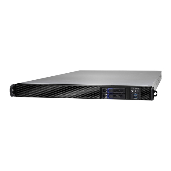
IT environment but also offers a smooth path for future application usage. ® TYAN also offers the GA88-B5631 in a version that can support up to two 2.5” Hot-Swap SSDs/HDDs.GA88-B5631 uses rack-mountable 1U chassis featuring a robust structure and a solid mechanical enclosure. - Page 15 Features TYAN GA88-B5631 (B5631G88V2HR-2T-N) Form Factor 1U Rackmount Chassis Model GA88 System Dimension (D x W x 34.5" x 17.24" x 1.7" (885 x 438 x 43.5mm) Motherboard S5631GM2NR-2T Buttons (1) PWR, (1) RST, (1) ID (1) PWR, (1) HDD, (2) LAN, (1)
- Page 16 1.2V PCI-E (5) PCI-E Gen3 x16 slots M2091-R, PCI-E x16 1U riser card (right), (3) M5631-R16-1, PCI-E x16 Expansion Slots Pre-install TYAN @front, 1U riser card (right), Riser Card M5631-R16-2, PCI-E x16 @rear, 1U riser card (right) Port Q'ty (2) 10GbE ports, (1) PHY...
- Page 17 - 40° C ~ 70° C (-40° F ~ 158° F) Operating Environment In/Non-operating 90%, non-condensing at 35° C Humidity RoHS RoHS 6/6 Compliant (1) Web User's manual, (1) Quick Manual Installation Guide Package Contains Installation CD (1) TYAN installation CD (1) GA88-B5631 w/NV Barebone Tesla-aware FW Barebone...
-
Page 18: Standard Parts List
Standard Parts List This section describes GA88-B5631 package contents and accessories. Open the box carefully and ensure that all components are present and undamaged. The product should arrive packaged as illustrated below. 1.2.1 Box Contents (1) 1U chassis ... -
Page 19: About The Product
About the Product The following views show you the product. 1.3.1 System Front View M1716G75 Front Panel Board Switch and LED Indication State LED Color Behavior Power/ Power On Green System Power On / Green Solid On System ID LED Power Off / Green Off Power Off ID free... -
Page 20: System Rear View
1.3.2 System Rear View Description Type-A USB3.0 Ports 1Gb RJ45 LAN from Realtek RTL8211E (dedicated for BMC/IPMI) 10Gb RJ45 LAN from Intel X550-AT2 (LAN2) 10Gb RJ45 LAN from Intel X550-AT2 (LAN1) VGA Port (1)+(1) 1600W RPSU GPU Card Slot PCI-E Gen3 x16 Slot, support low profile add-on card... -
Page 21: Internal View
1.3.3 Internal View system Fans CPU and Memory Socket PCIE Riser Card ( with M2091-R) Power Supply Cage M5631-R16-1F-1 Riser Card (FH/FL/DW PCI-E Gen.3 x16 slot) M5631-R16-1F-2 Riser Card (FH/FL/DW PCI-E Gen.3 x16 slot) -
Page 22: Chapter 2: Setting Up
Working on a system that is connected to a power supply can be extremely dangerous. Follow the guidelines below to avoid damage to GA88-B5631 or injury to yourself. Ground yourself properly before removing the top cover of the ... - Page 23 The motherboard is pre-installed in the system. When removing the motherboard, always place it on a grounded anti-static surface until you are ready to reinstall it. Hold electronic circuit boards by the edges only. Do not touch the components on the board unless it is necessary to do so.
-
Page 24: Installing Motherboard Components
2.1.1 Removing the Chassis Cover Follow these instructions to remove GA88-B5631 chassis cover. Remove the top screw on the chassis cover as in the small diagram. Loosen the Thumb screw on the back side of the chassis as in the small diagram in a counterclockwise direction. -
Page 25: Installing The Cpu And Heat Sink
2.1.2 Installing the CPU and Heat sink Follow the steps below on installing CPUs and CPU heat sinks. Locate the CPU socket. Remove the CPU protection cap. Put the Narrow-Fabric processor on the Carrier hook clips. Align and install the processor on the carrier. Carefully flip the heatsink. - Page 26 Place the heatsink on top of the CPU. Align the heatsink on the CPU socket by the guide pins and make sure the gold arrow is located in the correct direction. Then place the heatsink onto the top of the CPU socket. To secure the heatsink, use a T30 Security Torx to tighten the screws in a sequential order (1->2 ->...
-
Page 27: Installing The Memory
2.1.3 Installing the Memory Follow these instructions to install the memory modules onto the motherboard. Press the memory slot locking levers in the direction of the arrows as shown in the following illustration. 2. Align the memory module with the slot. When inserted properly, the memory slot locking levers lock automatically onto the indentations at the ends of the module. -
Page 28: Installing Hard Drives
2.1.4 Installing Hard Drives The GA88-B5631 supports 2 2.5” Hard Drives. Follow these instructions to install a hard drive. 2.5” Hard Disk Drive Located at the 2.5” HDD tray. Press the locking lever to release the 2.5”SSD/ HDD tray Pull out the 2.5”SSD/ HDD tray. - Page 29 Remove the 4 screws to detach HDD tray bracket. Place a hard drive into the drive tray. Use four screws to secure the HDD. Reinsert the HDD tray into the chassis. Press the locking lever to lock the SSD/ HDD tray.
- Page 30 Activity LED Status LED Description Color: Green Color: Amber No Driver Present or power disconnected Solid On Drive present, no activity Blinking Drive present, with activity Do not care Solid On HDD Fail Do not care Blinking @1Hz Drive Locate Identify Do not care Blinking @4Hz Rebuilding...
-
Page 31: Installing The Add-On Card
2.1.5 Installing the Add-On Card The GA88-B5631 has one preinstalled M2091-R riser card. You can install an Add-On card into the expansion slot which is available with riser card. The following instructions are for Add-On card installation. You may refer to the procedures below for the installation. - Page 32 4. Reinstall the M2091-R riser card to the chassis and secure with one screw.
-
Page 33: Rack Mounting
2.2.1 Installing the Server in a Rack Follow these instructions to mount the TYAN GA88-B5631 into an industry standard 19" rack. NOTE: Before mounting the TYAN GA88-B5631 in a rack, ensure that all internal components have been installed and that the unit has been fully tested. -
Page 34: Installing The Outer Rails To The Rack
Pull the inner sliding rail forward to secure it to the chassis. 2.2.3 Installing the Outer Rails to the Rack Secure the outer rails to the rack. -
Page 35: Rack Mounting The Server
2.2.4 Rack mounting the Server Lift the unit and then insert the inner slide rails into the middle rails. Push the whole system into the rack. -
Page 36: Chapter 3: Replacing Pre-Installed Components
Chapter 3: Replacing Pre-Installed Components Introduction This chapter explains how to replace the pre-installed components, including the S5631GM2NR-2T Motherboard, M1716G75-FPB Front Panel Board, M1287G88-BP12-2 Backplane, M5631-R16-1F-1/ M5631-R16-1F-2/M2091-R Riser Card, System Fan and Power Supply etc. Disassembly Flowchart The following flowchart outlines the disassembly procedure. -
Page 37: Removing The Cover
Removing the Cover Before replacing any parts you must remove the chassis cover. Follow Chapter 2.1.1 to remove the cover of GA88-B5631. Replacing the Riser Card The GA88-B5631 has preinstalled (3) M5631-R16-1F-1 and (1) M5631-R16-1F-2 and (1) M2091-R riser cards. - Page 38 The following instructions are for how to detach the PCIE riser card and installation. You may refer to the procedures below for the installation. 1. Remove the 3 screws to release the M5631-R16-1F-1 riser card. 2. Remove the 3 screws to release the M5631-R16-1F-2 riser card.
- Page 39 3.4.1 Riser card Feature M5631-R16-1F-1 M5631-R16-1F-2...
-
Page 40: Replacing The Hdd Backplane
Replacing the HDD Backplane Follow these instructions to replace the M1287G88-BP12-2 Front Panel Board. 4. Disconnect all the cables connected to the HDD Backplane. 5. Remove the two screws securing the bracket to the chassis base. -
Page 41: Hdd Backplane Features
3.5.1 HDD Backplane Features Front View Rear View PCB Dimensions: 93*36*2mm Layer: 4 layers (2) SATA Connectors (1) JTAG Jumper(J1) Integrated I/O (1) SGPIO Connector(J2) (2) Mini-SAS HD connector (1) 4 Pin Power connector... -
Page 42: Connector Definition
3.5.2 Connector Definition HDD0: HDD Connector Definition Definition SAS_TX0+ SAS_TX0- SAS_RXBN0 SAS_RXBP0 SAS0_PRESENT_L HD0_V5 VDD_5_RUN VDD_5_RUN HD0_PRS_L SAS0_LED HD0_V12HD VDD_5_RUN VDD_5_RUN GND1 GND2 HDD1: HDD Connector Definition Definition SAS_TX1+ SAS_TX1- SAS_RXBN1 SAS_RXBP1 SAS0_PRESENT_L HD1_V5 VDD_5_RUN VDD_5_RUN HD1_PRS_L SAS1_LED HD1_V12HD VDD_5_RUN VDD_5_RUN GND1 GND2... - Page 43 SATA0: SATA Connector Definition Definition SAS_TX0+ SAS_TX0- SAS_RXBN0 SAS_RXBP0 SATA1: SATA Connector Definition Definition SAS_TX1+ SAS_TX1- SAS_RXBN1 SAS_RXBP1 J1: JTAG Connector Definition Definition CPLD_JTAG_TCK CPLD_JTAG_TDO VDD_3P3_RUN CPLD_JTAG_TMS CPLD_JTAG_TDI J2: SGPIO Connector Definition Definition SMBUS_3V3_CLK SAS_SIO_DIN_A SMBUS_3V3_DATA SAS_SIO_DOUT_A SAS_SIO_END_A SAS_SIO_CLK_A VCC3_AUX PW1: Power Connector Definition Definition...
-
Page 44: Replacing The System Fan
Replacing the System Fan 1. GA88-B5631 has equipment with ten system fans which you need to replace up. 2. Disconnect the fan cable. 3. Lift the fan which you need to replace a new one. - Page 45 Fan Sequence...
-
Page 46: Replacing The Front Panel Board
Replacing the Front Panel Board Follow these instructions to replace the M1716G75-FPB Front Panel Board. 1. Disconnect both cables from the front panel board. 2. Unscrew the front panel board module. 3. Unscrew the front panel board from the front panel tray for a new one. 4. -
Page 47: Front Panel Board Features
3.7.1 Front Panel Board Features Front View Rear View Form Factor 28 x 35.4 x 1.6 (mm), 4-layer PCB I/O: (2) USB3.0 Port LED Indicators: (1) HDD LED (1) Warning LED Specifications (2) LAN LED (1) Power/ID LED Switch: (1) Reset Button (1) ID Button (1) Power Button... -
Page 48: Connector Definition
3.7.2 Connector Definition Location Definition HDD_LED HDD LED BMC_EVENT_LED Warning LED LAN1_LED LAN1 LED LAN2_LED LAN2 LED ID_PW_LED Power/ID LED USB3.0 Port USB3.0 Port Reset Button ID Button Power Button Front Panel Control Board Connector USB3.0 Connector J7: USB3.0 Header Definition Definition USB3_VCC_FPB... - Page 49 J4: FPIO Connector Definition Definition PW_LED+ VCC_FPB ID_LED+ PW_LED- ID_LED- HD_LED+ BMC_HW_FAULT_N HD_LED- BMC_SYS_FAULT_N FP_PWR_BTN_N LAN1_LED+ LAN1_LED- FP_RST_BTN_N FP_IDLED_BTN_N TEMP_SENSOR LAN2_LED+ HD_FAIL_LED- LAN2_LED- GND1 GND2...
-
Page 50: Replacing The Power Supply
Replacing the Power Supply To replace the power supply follow these instructions. Press the tab as shown in the diagram and pull out the power. Free the power from the power socket. Replace a new single power and reinsert it into the power socket following the above steps in reverse. -
Page 51: Replacing The Motherboard
Replacing the Motherboard Follow these instructions to remove all of below mentioned cables on the motherboard from the chassis. 1. Disconnect all the fan cables. 2. Disconnect all the fan cables. - Page 52 2. Disconnect the front panel control cable. 3. Disconnect the SATA and USB cable.
-
Page 53: Chapter 4: Installing Gpu Cards
® NVDIA Tesla The GA88-B5631 supports three PCI-E Riser Card Brackets. A power cable (2x4p) is required for GPU cards. Follow these instructions to install GPU card in your system. Remove the screw marked in the red circle and disconnect the power cable to lift up the GPU front bracket. - Page 54 Remove the 4 screws as in the image to take off the GPU original shielding. (NOTE: After detach the Tesla original shielding, screw back the one screw on back side to the GPU card, and remain the other 3 screws for GPU front bracket installation.) Secure the GPU cards to the GPU front bracket with 5 screws (use GPU screws and M3_L4 screws in the screw pack from Accessory box) and plug in...
-
Page 55: Installing The #4 Gpu Card (Tesla)
Reinsert the GPU module with one screw to the chassis and connect the GPU power cable. Installing the #4 GPU card (Tesla) Remove the 2 screws to take out the GPU back bracket. Remove the 2 screws and pull out the back brackets in the direction of the arrow. - Page 56 Insert the Tesla GPU card onto the M5631-R16-1F-2 riser card. Secure the GPU card onto the GPU bracket. Connect the GPU power cable. Reinsert the GPU module to the chassis and connect the GPU power cable.
- Page 57 Cable Routing (Tesla)
- Page 58 ® NVIDIA GTX (Optional) The same procedure as step 1~2 in chapter 4.1 Installing the #1~3 GPU cards to take out the GPU front bracket. Release the nylon cable ties marked with red circle. ® Release the screw to take off the NVIDIA rear bracket.
- Page 59 ® The following picture is NVIDIA GTX GPU card. Release the 5 screws from the GPU card bracket. Then remove the bracket as in the picture. (NOTE: After detach the GTX original shielding, screw back the one screw on back side to the GPU card, and remain the other screws for GPU front bracket installation.)
-
Page 60: Installing The #1~3 Gpu Cards (Gtx)
Installing the #1~3 GPU cards (GTX) ® Insert the NVIDIA GTX card into the GPU front bracket. ® Secure the Nvidia GTX GPU card into the bracket with the 6 screws. (use GPU screws and M3_L4 screws pack from Accessory box) - Page 61 Connect the GTX GPU card power cable. Reinsert the GPU module with 1 screw to the chassis. Connect the GTX GPU power cable to the motherboard.
-
Page 62: Installing The #4 Gpu Cards (Gtx)
Installing the #4 GPU cards (GTX) The same procedure as step1~2 in chapter 4.2 Installing the #4 GPU cards to take out the GPU back bracket. 1. Insert the GTX GPU card onto the M5631-R16-1F-2 riser card. 2. Secure the GPU card onto the GPU back bracket. Connect the GTX GPU card power cable. - Page 63 Secure the GTX GPU module to the chassis with 2 screws and connect the power cable to the motherboard. Now the installation of Tesla and GTX GPU card has completed.
- Page 64 Cable Routing (GTX)
-
Page 65: Installing The Air Duct
Installing the Air Duct The GA88-B5631 system chassis air duct equipped in the accessory kit. Follow the instruction below to install all the 4 air ducts onto the chassis kit. 1. Align by the guide pins marked with red arrow and then install the air ducts onto the chassis. - Page 66 3. The air duct installation onto the chassis has been complete.
-
Page 67: Chapter 5: Mainboard Information
Chapter 5: Mainboard Information You are now ready to install your motherboard. How to install our products right… the first time The first thing you should do is read this user‟s manual. It contains important information that will make configuration and setup much easier. Here are some precautions you should take when installing your motherboard: (1) Ground yourself properly before removing your motherboard from the antistatic bag. -
Page 68: Board Image
Board Image S5631 This picture is representative of the latest board revision available at the time of publishing. The board you receive may not look exactly like the above picture. -
Page 69: Block Diagram
Block Diagram B5631 Block Diagram... -
Page 70: Mainboard Mechanical Drawing
Mainboard Mechanical Drawing... -
Page 71: Board Parts, Jumpers And Connectors
The board you receive may not look exactly like the above diagram. The DIMM slot numbers shown above can be used as a reference when reviewing the DIMM population guidelines shown later in the manual. For the latest board revision, please visit our web site at http://www.tyan.com. - Page 72 21. CPU0 PWOK LED (P0_PG_LED1) 42. CATERR LED (CAT_LED1) 43. CPU Error LED (ERR_LED1) Jumpers a. TYAN Module Header (DBG_HD1) g. Intel MIC card/ NVIDIA GPU card Select Jumper (3PHD8) b. IPMB Pin Header (IPMB_HD1) h. PSU Alert Function Jumper (3PHD9) c.
- Page 73 Signal SOUT CPU0_FAN_1: 4-pin CPU0 FAN Connector Signal P12V_IN TACH Use this header to connect the cooling fan to your motherboard to keep the system stable and reliable. DBG_HD1: TYAN Module Header Signal Signal VCC3 FRAME# LAD0 LAD1 RESET# LAD2...
- Page 74 TYPEA_USB3: Type-A USB3.0 Header (blue) Signal Signal USB3_VCC USB2_N8 USB2_P8 USB3_N3_RX USB3_P3_RX USB3_N3_TX USB3_P3_TX USB3_FPIO1: Front USB3.0 Connector Signal Signal USB3_VCC USB3_N5_RX USB3_VCC USB3_P5_RX USB3_N6_RX USB3_P6_RX USB3_N5_TX USB3_P5_TX USB3_N6_TX USB3_P6_TX USB2_N4 USB2_P4 USB2_N6 USB2_P6 INTRUDER_HD1: Chassis Intrusion Header Signal Signal PCH_INTRUDER_N CLEAR_BTN1: RTC Reset Button for Clear CMOS You can reset the CMOS settings by using this button, if...
- Page 75 DOM_5V_PW1/DOM_5V_PW2: SSATA DOM Power Connector Signal Signal VCC5 SSATA_DOM4/SSATA_DOM5: SSATA DOM Connector Signal Signal SSATA_TX+ SSATA_TX- SSATA_RX- SSATA_RX+ VCC5 SSATA_SGPIO1: PCH SATA SGPIO Pin Header for HD BP Signal Signal BMC_SCL BMC_DAT SGPIO_DOUT SGPIO_LOAD SGPIO_CLK VCC3_AUX IPMB_HD1: IPMB Connector Signal BMC_SMB_DATA BMC_SMB_CLK SATA2/SATA3: SATA Connector...
- Page 76 3PHD3: ME Firmware Recovery Mode Jumper Signal FM_ME_RCVR_N Pin1-2 closed: Normal (Default) Pin2-3 closed: ME Firmware Recovery Mode 3PHD6/SPHD7: BMC Console Port5 Select Jumper (for BMC Debug) Signal Signal BMC_TXD5 TXD_OUT BMC_RXD5 RXD_OUT BMC_TXD BMC_RXD Pin1-2 closed: BMC COM2 Debug (Default) Pin2-3 closed: BMC COM5 Debug 3PHD8: Intel MIC card/NVIDIA GPU card Select Jumper...
- Page 77 J109: Select SPI Path Jumper Signal Signal 3.3V_AUX SPI-BUS-1 Pin1-2 closed: Normal Mode (Default) Pin2-3 closed: Pass through mode FAN1~FAN10: 8-pin System FAN Power Connector Signal Signal GND1 VCC12 FAN TACH1 FAN PWM1 GND2 VCC12 FAN TACH2 FAN PWM2 J116: small 4-pin Power Connector Signal Signal P12V_IN...
-
Page 78: Tips On Installing Motherboard In Chassis
Tips on Installing Motherboard in Chassis Before installing your motherboard, make sure your chassis has the necessary motherboard support studs installed. These studs are usually metal and are gold in color. Usually, the chassis manufacturer will pre-install the support studs. If you are unsure of stud placement, simply lay the motherboard inside the chassis and align the screw holes of the motherboard to the studs inside the case. - Page 79 NOTE: Be especially careful to look for extra stand-offs. If there are any stand-offs present that are not aligned with a mounting hole on the motherboard, it will likely short components on the back of the motherboard when installed. This will cause malfunction and/or damage to your motherboard.
-
Page 80: Connecting External Devices
Connecting External Devices Connecting external devices to the motherboard is an easy task. The motherboard supports a number of different interfaces through connecting peripherals. See the following diagrams for the details. LAN (IPMI) Dedicate to BMC VGA Port LAN2 (IX550) LAN1(X550) NOTE: Peripheral devices can be plugged straight into any of these... - Page 81 1Gbps LAN Port LAN Indication 10/100/1000 Mbps LAN Link/Activity LED Scheme Left LED Right LED (Link/Activity) (Speed) No Link Solid Green Link 10 Mbps Blinking Green Active Solid Green Solid Green Link 100 Mbps Blinking Green Solid Green Active Solid Green Solid Amber Link 1000 Mbps...
-
Page 82: Memory
Memory Before installing memory, ensure that the memory you have is compatible with the motherboard and processor. Check the TYAN Web site at http://www.tyan.com for details of the type of memory recommended for your motherboard. Supports twelve (6+6) DDR4 RDIMM/RDIMM 3DS/LRDIMM/LRDIMM 3DS 2666,... - Page 83 3. Populate the same DIMM type in each channel, specifically - Use the same DIMM size - Use the same # of ranks per DIMM 4. Dual-rank DIMMs are recommended over single-rank DIMMs. 5. Always install with CPU0 Socket and DIMM_0 Slot first, following the alphabetical order. http://www.tyan.com...
-
Page 84: Power Supply
Power Supply There are five (5) power connectors on your S5631 motherboard. The S5631 supports EPS 12V power supply. PWR1: 4-pin Power Connector Signal Signal P12V_IN VCC5 PE_PW1/PE_PW2/PE_PW4/PE_PW5: 8-pin GPU Power Connector Signal Signal P12V_IN P12V_IN P12V_IN P12V_IN http://www.tyan.com... -
Page 85: Chapter 6: Bios Setup
The table below shows how to navigate in the setup program using the keyboard. Function Left/Right Arrow Keys Change from one menu to the next Up/Down Arrow Keys Move between selections Enter Open highlighted section PgUp/PgDn Keys Change pages Change options Exit http://www.tyan.com... -
Page 86: Getting Help
The following pages provide the details of BIOS menu. Please be noticed that the BIOS menu are continually changing due to the BIOS updating. The BIOS menu provided are the most updated ones when this manual is written. Please visit TYAN‟s website at http://www.tyan.com for the information of BIOS updating. -
Page 87: Main Menu
BIOS Information It displays BIOS related information. Product Name It displays Product information. BIOS Version It displays BIOS version information Build Date and Time It displays the time when built Access Level Adminstrator Platform Information It displays the platform information http://www.tyan.com... - Page 88 It displays the total memory size. System Date Set the Date. Use Tab to switch between Date elements. Default Ranges: Year: 2010-2079 Months: 1-12 Days: dependent on month System Time Set the Time. Use Tab to switch between Time elements. http://www.tyan.com...
-
Page 89: Advanced Menu
This formset allows the user to manage Intel® Virtual RAID on CPU. Trusted Computing Trusted Computing Settings. ACPI Settings System ACPI Parameters. Hardware Health Configuration Hardware health Configuration Parameters. Onboard Device Configuration Onboard Device Configuration. AST2500 Super IO Configuration System Super IO Chip Parameters. http://www.tyan.com... - Page 90 Serial Port Console Redirection. Option ROM Dispatch Policy Option ROM Dispatch Poligy. PCI Subsystem Settings PCI, PCI-X and PCI Express Settings. Network Stack Configuration Network Stack Settings. CSM Configuration CSM configuration: Enable/Disable, Option ROM execution settings, etc. USB Configuration USB Configuration Parameters. http://www.tyan.com...
-
Page 91: Intel ® Virtual Raid On Cpu
/ PStack1 (Slot 5~8) / PStack2 (Slot 9~12) Step 2. Suppose the card is installed in CPU0 Slot 3, then Intel® VMD for Volume Management Device for PStack0 will be set to [Enabled]. Step 3. Save changes and reboot. http://www.tyan.com... -
Page 92: Trusted Computing
6.3.2 Trusted Computing Security Device Support Enables or Disables BIOS support for security device. O.S. will not show Security Device. TCG EFI protocol and INT1A interface will not be available. Enabled / Disabled http://www.tyan.com... -
Page 93: Acpi Settings
ACPI Settings Enable ACPI Auto Configuration Enable or disable BIOS ACPI Auto Configuration. Disabled / Enabled Enable Hibernation Enable or disable System ability to Hibernate (OS/S4 Sleep State). This option may not be effective with some OS. Disabled / Enabled http://www.tyan.com... -
Page 94: Hardware Health Configuration
6.3.4 Hardware Health Configuration Auto Fan Control Auto Fan Control Help. Disabled / Enabled BMC Alert Beep Enable/Disable BMC Alert Beep. On / Off PMBus Support PMBus Support Enabled / Disabled http://www.tyan.com... - Page 95 6.3.4.1 Sensor Data Register Monitoring When you enter the Sensor Data Register Monitoring submenu, you will see the following dialog window pop out. Please wait 8~10 seconds. http://www.tyan.com...
- Page 96 NOTE: SDR can not be modified. Read only. http://www.tyan.com...
-
Page 97: Onboard Device Configuration
6.3.5 Onboard Device Configuration Onboard LAN (Intel X550) LAN Enable/Disable control function. Disabled / Enabled Chassis Intrusion detect ENABLED: when a chassis open event is detected, the BIOS will record the event. Disabled / Enabled http://www.tyan.com... -
Page 98: Ast2500 Super Io Configuration
6.3.6 AST2500 Super IO Configuration Super IO Chip Read only. http://www.tyan.com... - Page 99 / IO=3F8h, IRQ=3, 4, 5, 6, 7, 9, 10, 11, 12; / IO=2F8h; IRQ=3, 4, 5, 6, 7, 9, 10, 11, 12; / IO=3E8h, IRQ=3, 4, 5, 6, 7, 9, 10, 11, 12; / IO=2E8h, IRQ=3, 4, 5, 6, 7, 9, 10, 11, 12; http://www.tyan.com...
-
Page 100: S5 Rtc Wake Settings
Select 0-23. For example enter 3 for 3am and 15 for 3pm. Wake up minute Select 0-59 for Minute. Wake up second Select 0-59 for Second. When Wake system from S5 is set to [Dynamic Time] Wake up Minute increase 1-5. http://www.tyan.com... -
Page 101: Serial Port Console Redirection
Console redirection enable or disable. Disabled / Enabled Legacy Console Redirection Settings Legacy Console redirection settings. Console Redirection Settings The settings specify how the host computer (which the user is using) will exchange data. Both computers should have the same or compatible settings. http://www.tyan.com... - Page 102 0 if the num of 1‟s in the data bits is even. Odd: parity bit is 0 if the num of 1‟s in the data bits is odd. Mark: parity bit is always 1. Space: parity bit is always 0. Mark and Space parity do not allow for error detection. None / Even / Odd / Mark / Space http://www.tyan.com...
- Page 103 Redirection after BIOS POST The settings specify if BootLoader is selected than Legacy console redirection is disabled before booting to Legacy OS. Default value is Always Enable which means Legacy Console Redirection is enabled for Legacy OS. Always Enable / BootLoader http://www.tyan.com...
- Page 104 6.3.8.2 Legacy Console Redirection Settings Legacy Serial Redirection Port Select a COM port to display redirection of Legacy OS and Legacy OPROM Messages. COM1 / COM2 http://www.tyan.com...
- Page 105 VT-UTF8 / VT100 / VT100+ / ANSI Bits per Second Select serial port transmission speed. The speed must be matched on the other side. Long or noisy lines may require lower speeds. 115200 / 9600 / 19200 / 57600 http://www.tyan.com...
- Page 106 „start‟ signal can be sent to restart the flow. Hardware flow control uses two wires to send start/stop signal. None / Hardware RTS/CTS / Software Xon/Xoff Data Bits / Parity / Stop Bits Read only. http://www.tyan.com...
-
Page 107: Option Rom Dispatch Policy
Onboard LAN1 Option ROM type Select onboard LAN1 Option ROM type. PXE / iSCSI Onboard LAN2 (X550) Enable or disable onboard LAN2 Option ROM. Disabled / Enabled PCIE_5 Empty Enable or Disable Option ROM execution for selected Slot. Disabled / Enabled http://www.tyan.com... -
Page 108: Pci Subsystem Settings
Enables or Disables 64bit capable Devices to be Decoded in Above 4G Address Space (Only if System Supports 64 bit PCI Decoding). Enabled / Disabled SR-IOV Support If system has SR-IOV capable PCIe Devices, this option Enables or Disables Single Root IO Virtualization Support. Enabled / Disabled http://www.tyan.com... -
Page 109: Csm Configuration
UEFI and Legacy / Legacy only / UEFI only Network Controls the execution of UEFI and Legacy PXE OpROM. Legacy / Do not launch / UEFI Storage Controls the execution of UEFI and Legacy Storage OpROM. Legacy / Do not launch / UEFI http://www.tyan.com... - Page 110 Video Controls the execution of UEFI and Legacy Video OpROM Legacy / Do not launch / UEFI Other PCI Devices Determines OpROM execution policy for devices other than Network, Storage, or Video. Legacy / Do not launch / UEFI http://www.tyan.com...
-
Page 111: Usb Configuration
XHCI Hand-off This is a workaround for OSes without XHCI hand-off support. The XHCI ownership change should be claimed by XHCI driver. Enabled / Disabled USB Mass Storage Driver Support Enable/Disable USB Mass Storage Driver Support. Enabled / Disabled http://www.tyan.com... - Page 112 Maximum time the device will take before it properly reports itself to the Host Controller. „AUTO‟ uses default value: for a Root port it is 100 ms, for a Hub port the delay is taken from Hub descriptor. Auto / Manual http://www.tyan.com...
-
Page 113: Platform Configuration
Platform Configuration PCH Configuration Displays and provides option to change the PCH Settings. Server ME Configuration Configure Server ME Technology Parameters. http://www.tyan.com... -
Page 114: Pch Configuration
PCH sSATA Configuration sSATA devices and settings. USB Configuration USB Configuration Settings. PCH DFX Configuration PCH DFX Configuration Options. PCH state after G3 Select S0/S5 for ACPI state after a G3. S0 / Onboard / S5 / Leave power state unchanged http://www.tyan.com... - Page 115 L1 Substates PCI Express L1 Substates settings. Disabled / L1.1 / L1.2 / L1.1 & L1.2 PCIe Speed Configure PCIe Speed. Auto / Gen1 / Gen2 / Gen3 Max Payload Size PCIE Max Payload Size Selection. MPL128B / MPL256B http://www.tyan.com...
- Page 116 Determines how SATA controller(s) operate. AHCI / RAID Port 0 Enable or Disable SATA Port. Disabled / Enabled Hot Plug Designates this port as Hot Pluggable. Disabled / Enabled Configure as eSATA Configures port as External SATA (eSATA). Disabled / Enabled http://www.tyan.com...
- Page 117 Identify the SATA port is connected to Solid State Drive or Hard disk Drive. Hard Disk Drive / Solid State Drive SATA Topology Identify the SATA Topology if it is Default or ISATA or Flex or DirectConnect or M2. Unknown / ISATA / Direct Connect / Flex / M2 http://www.tyan.com...
- Page 118 6.4.1.3 PCH sSATA Configuration http://www.tyan.com...
- Page 119 Identify the SATA port is connected to Solid State Drive or Hard disk Drive. Hard Disk Drive / Solid State Drive SATA Topology Identify the SATA Topology if it is Default or ISATA or Flex or DirectConnect or M2. Unknown / ISATA / Direct Connect / Flex / M2 http://www.tyan.com...
- Page 120 6.4.1.4 USB Configuration XHCI Idle L1 Enabled XHCI Idle L1. Disabled to workaround USB3 hot plug will fail after 1 hot plug removal. Please put the system to G3 for the new settings to take effect. Enabled / Disabled http://www.tyan.com...
- Page 121 Enabled / Disabled Enable/Disable ADR Timer Held-off for DEBUG PURPOSES ONLY!. Enabled / Held-off ADR timer expire time Select proper ADR timer value: 25uS, 50uS, 100uS or 0. 25 uS / 50 uS / 100 uS / 0 us http://www.tyan.com...
- Page 122 ADR timer multiplier Select proper ADR timer multiplier: x1, 8, 24, 40, 56, 64, 72, 80, 88, 96. x1 / x8 / x24 / x40 / x56 / x64 / x72 / x80 / x88 / x96 http://www.tyan.com...
-
Page 123: Miscellaneous Configuration
6.4.2 Miscellaneous Configuration Active Video Select active video type. Auto / Onboard Device / PCIE Device http://www.tyan.com... -
Page 124: Server Me Configuration
6.4.3 Server ME Configuration Read only. http://www.tyan.com... -
Page 125: Socket Configuration
Displays the provides option to change the Common RefCode Settings. Memory Configuration Displays and provides option to change the Memory Settings. IIO Configuration Displays and provides option to change the IIO Settings. Advanced Power Management Configuration Displays and provides option to change the Power Management Settings. http://www.tyan.com... -
Page 126: Processor Configuration
Disabled / Enabled Execute Disable Bit When disabled, forces the XD feature flag to always return 0. Disabled / Enabled Enable Intel® TXT Enables Intel® TXT. Disabled / Enabled Enables the Vanderpool Technology, takes effect after reboot. Disabled / Enabled http://www.tyan.com... - Page 127 Lock or Unlock chipset. Disabled / Enabled Hardware Prefetcher MLC Streamer Prefetcher (MSR 1A4h Bit[0]). Enabled / Disabled Adjacent Cache Prefetch MLC Spatial Prefetcher (MSR 1A4h Bit[1]). Enabled / Disabled Extended APCI Enable/Disable extended APIC support. Disabled / Enabled http://www.tyan.com...
-
Page 128: Common Refcode Configuration
Per stack mmioh resource assignments are multiples of the granularity where 1 unit per stack is the default allocation. 1G / 4G / 16G / 64G / 256G / 1024G Numa Enable or Disable Non uniform Memory Access (NUMA). Disabled / Enabled http://www.tyan.com... -
Page 129: Memory Configuration
Auto / POR / Disable Data Scrambling for NVMDIMM Enable – Enables data scrambling for NVMDIMM. Disable – Disables this feature. Auto – Sets it to the MRC default setting; current default is Enable. Auto / Disabled / Enabled http://www.tyan.com... - Page 130 6.5.3.1 Memory Topology Read only. http://www.tyan.com...
- Page 131 Mirror Enable will disable XPT Prefetch. Disabled / Partial Mirror mode 1LM / Partial Mirror mode 2LM Memory Rack Sparing Enable/Disable Memory Rank Sparing. Disabled / Enabled Correctable Error Threshold Correctable Error Threshold (1 – 32767) used for sparing, tagging, and leaky bucket. http://www.tyan.com...
- Page 132 Enable/Disable ADDDC Sparing. Disabled / Enabled Patrol Scrub Enable/Disable Patrol Scrub. Disabled / Enabled 6.5.5 IIO Configuration Socket0 Configuration Socket0 Configuration Intel® VT for Directed I/O (VT-d) Press <Enter> to bring up the Intel® VT for Directed I/O (VT-d) Configuration menu. http://www.tyan.com...
- Page 133 Enable/Disable PCIe ACPI Hot Plug globally, or allow per-port control. When Disabled, MSI is generated on HP event. When Enabled, _HPGPE message is generated. Disabled / Enable / Per-Port PCIe Access Control Services Enable or disable Access Control Services (ACS) in PCIe Downstream Switch Port. Disabled / Enable http://www.tyan.com...
- Page 134 Selects PCIe port Bifurcation for selected slot(s). x4x4x4x4 / x4x4x8 / x8x4x4 / x8x8 / x16 / Auto Socket 0 PcieBr1D00F0 – Port 1A Settings related to PCI Express Ports (0/1A/1B/1C/1D/2A/2B/2C/2D/3A/3B/3C/3D/4A/5A). Socket 0 PcieBr2D00F0 – Port 2A Settings related to PCI Express Ports (0/1A/1B/1C/1D/2A/2B/2C/2D/3A/3B/3C/3D/4A/5A). http://www.tyan.com...
- Page 135 Socket 0 PcieBr3D00F0 – Port 3A Settings related to PCI Express Ports (0/1A/1B/1C/1D/2A/2B/2C/2D/3A/3B/3C/3D/4A/5A). Socket 0 PcieBr4D00F0 – MCP 0 Settings related to PCI Express Ports (0/1A/1B/1C/1D/2A/2B/2C/2D/3A/3B/3C/3D/4A/5A). Socket 0 PcieBr5D00F0 – MCP1 Settings related to PCI Express Ports (0/1A/1B/1C/1D/2A/2B/2C/2D/3A/3B/3C/3D/4A/5A). http://www.tyan.com...
- Page 136 This option disables the link so that the no training occurs but the CFG space is still active. Enabled / Disabled Link Speed Choose Link Speed for this PCIe port. Auto / Gen 1 (2.5 GT/s) / Gen 2 (5 GT/s) / Gen 3 (8 GT/s) http://www.tyan.com...
- Page 137 HP capable. Disable is used to disable the port and hide its CFG space. Auto / Disabled / Enabled Hot Plug Capable This option specifies if the link is considered Hot Plug capable. Disabled / Enabled http://www.tyan.com...
- Page 138 Auto / Gen 1 (2.5 GT/s) / Gen 2 (5 GT/s) / Gen 3 (8 GT/s) PCI-E ASPM Support This option enables/disables the ASPM (L1) support for the downstream devices. Auto / L1 Only / Disabled L0s Support When disabled, IIO never puts its transmitter in L0s state. Disabled / Enabled http://www.tyan.com...
- Page 139 Choose Link Speed for this PCIe port. Auto / Gen 1 (2.5 GT/s) / Gen 2 (5 GT/s) / Gen 3 (8 GT/s) PCI-E ASPM Support This option enables/disables the ASPM (L1) support for the downstream devices. Auto / L1 Only / Disabled http://www.tyan.com...
- Page 140 Disabled / Enabled 6.5.5.3 Intel® VT for Directed I/O (VT-d) Intel® VT for Directed I/O (VT-d) Enable/Disable Intel® Virtualization Technology for Directed I/O (VT-d) by reporting the I/O device assignment to VMM through DMAR ACPI Tables. Enabled / Disabled http://www.tyan.com...
- Page 141 6.5.5.4 Intel® VMD Technology http://www.tyan.com...
- Page 142 Intel® VMD for Volume Management Device for PStack1 Enable/Disable Intel® Volume Management Device Technology in this Stack. Disabled / Enabled Intel® VMD for Volume Management Device for PStack2 Enable/Disable Intel® Volume Management Device Technology in this Stack. Disabled / Enabled http://www.tyan.com...
- Page 143 P State Control Configuration Sub Menu, include Turbo, XE and ete. Hardware PM State Control Hardware P-State setting. CPU C State Control CPU C State setting. Package C State Control Package C State setting. CPU T State Control CPU T State setting. http://www.tyan.com...
- Page 144 Max Performance / Max Efficient / Set by Intel Node Manager Energy Efficient Turbo Energy Efficient Turbo Disable, MSR 0x1FC [19]. Enabled / Disabled Turbo Mode Enable/Disable processor Turbo Mode (requires EMTTM enabled too). Disabled / Enabled CPU Flex Ratio Override Enable/Disable CPU Flex Ratio Programming. Disabled / Enabled http://www.tyan.com...
- Page 145 Disable: Hardware chooses a P-state based on OS Request (Legacy P-States). Native Mode: Hardware chooses a P-state based on OS guidance. Out of Band Mode: Hardware autonomously chooses a P-state (no OS guidance). Disabled / Native Mode / Out of Band Mode / Native Mode with NO Legacy Support http://www.tyan.com...
- Page 146 Enable/Disable CPU C6 (ACPI C3) report to OS. Disabled / Enabled / Auto Enhanced Halt State (C1E) Core C1E auto promotion Control. Takes effect after reboot. Disabled / Enabled OS ACPI Cx Report CC3/CC6 to OS ACPI C2 or ACPI C3. ACPI C2 / ACPI C3 http://www.tyan.com...
- Page 147 6.5.5.5.4 Package C State Control Package C State Package C State limit. C0/C1 state / C2 state / C6 (non Retention) state / C6 (Retention) state / No Limit / Auto http://www.tyan.com...
- Page 148 6.5.5.5.5 CPU T State Control Software Controlled T-States Enable/Disable Software Controlled T-States. Disabled / Enabled http://www.tyan.com...
-
Page 149: Server Management
OS Watchdog Timer If enabled, starts a BIOS timer which can only be shut off by Management Software after the OS loads. Helps determine that the OS successfully loaded or follows the OS Boot Watchdog Timer policy. Enabled / Disabled http://www.tyan.com... - Page 150 Do Nothing / Reset / Power Down / Power Cycle BMC Logo Enable or Disable BMC Logo. Enabled / Disabled System Event Log Press <Enter> to change the SEL event log configuration. BMC network configuration Configure BMC network parameters. http://www.tyan.com...
-
Page 151: System Event Log
Choose options for reactions to a full SEL. Do Nothing / Erase Immediately Log EFI Status Codes Disable the logging of EFI Status Codes or log only error code or only progress code or both. Disabled / Both / Error Code / Progress Code http://www.tyan.com... -
Page 152: Bmc Network Configuration
Enable/Disable BMC Share Nic. Enabled / Disabled Configuration Address Source Select the configure LAN channel parameters statically or dynamically (by BIOS or BMC). Unspecified option will not modify any BMC network parameters during BIOS phase. Unspecified / Static / DynamicBmcDhcp / DynamicBmcNonDhcp http://www.tyan.com... - Page 153 Enable or Disable LAN1 IPV6 Support. Enabled / Disabled Configuration Address Source Select the configure LAN channel parameters statically or dynamically (by BIOS or BMC). Unspecified option will not modify any BMC network parameters during BIOS phase. Unspecified / Static / DynamicBmcDhcp http://www.tyan.com...
-
Page 154: Security
Set user password in the Create New Password window. After you key in the password, the Confirm New Password window will pop out to ask for confirmation. Security Frozen Mode Enable or disable HDD security freeze lock. Disable to support secure erase function. http://www.tyan.com... -
Page 155: Secure Boot
Secure boot activated when Platform Key (PK) is enrolled, System mode is User/Deployed, and CSM function is disabled. Disabled / Enabled Secure Boot Mode Secure Boot mode selector: Standard/Custom. In Custom mode Secure Boot Variables can be configured without authentication. Standard / Custom http://www.tyan.com... - Page 156 Save NVRAM content of all Secure Boot variables to the files (EFI_SIGNATURE_LIST data format) in root folder on a target file system device. Platform Key (PK) Enroll Factory Defaults or load certificates from a file: 1. Public Key Certificate in: a) EFI_SIGNATURE_LIST http://www.tyan.com...
- Page 157 EFI_CERT_SHA256, 384, 512 (bin) 2. Authenticated UEFI Variable 3. EFI PE/C0FF Image (SHA256) Key source: Default, External, Mixed, Test Set New / Append Authorized TimeStamps Enroll Factory Defaults or load certificates from a file: 1. Public Key Certificate in: http://www.tyan.com...
- Page 158 Enroll Factory Defaults or load certificates from a file: 1. Public Key Certificate in: a) EFI_SIGNATURE_LIST b) EFI_CERT_X509 (DER encoded) c) EFI_CERT_RSA2048 (bin) d) EFI_CERT_SHA256, 384, 512 (bin) 2. Authenticated UEFI Variable 3. EFI PE/C0FF Image (SHA256) Key source: Default, External, Mixed, Test Set New / Append http://www.tyan.com...
-
Page 159: Boot
Quiet Boot Enable or disable Quiet Boot option. Disabled / Enabled Wait for ‘ESC’ If Error Wait for „ESC‟ key to be pressed if error occurs. Disabled / Enabled Endless Boot Enable or disable Endless Boot. Disabled / Enabled http://www.tyan.com... - Page 160 Boot Option Priorities Boot Option #1~#4 Select the first/second boot device. Device Name / Disabled Network Device BBS Priorities Set the order of the legacy devices in this group. http://www.tyan.com...
-
Page 161: Network Device Bbs Priorities
6.8.1 Network Device BBS Priorities Boot Option #1/#2 Set the system boot order. Device Name / Disabled http://www.tyan.com... -
Page 162: Save & Exit
Reset system setup without saving any changes. Save Changes Save changes done so far to any of the setup options. Discard Changes Discard changes done so far to any of the setup options. Restore Defaults Restore/Load Default values for all the setup options. http://www.tyan.com... - Page 163 Save as User Defaults Save the changes done so far as User Defaults. Restore User Defaults Restore the User Defaults to all the setup options. Boot Override Read only. http://www.tyan.com...
-
Page 164: Chapter 7: Diagnostics
PNOR flash failure, you must contact your dealer for a replacement PNOR. There are no exceptions. TYAN does not have a policy for replacing PNOR chips directly with end users. In no event will TYAN be held responsible for damages done by the end user. -
Page 165: Hostboot Ipls Progress Code
Builds targeting ISTEP 06.06 Do Gard ISTEP 06.07 Clear deconfigured states ISTEP 06.08 Clean up MCS extent regs ISTEP 06.09 Setup centaur ref clocks ISTEP 06.10 Update SBE config data area ISTEP 06.11 Start the SBE engine on slave chips http://www.tyan.com... - Page 166 Cen TP Chiplet init 2 ISTEP 10.06 Cen TP Chiplet array init ISTEP 10.07 Cen TP Chiplet Start clocks ISTEP 10.08 Cen Chiplet Init ISTEP 10.09 Chiplet array init ISTEP 10.10 Cen DTS init ISTEP 10.11 Cen Scan overrides http://www.tyan.com...
- Page 167 ISTEP 13.07 Soft reset of DDR PHY macros ISTEP 13.08 DRAM initialize ISTEP 13.09 DRAM training ISTEP 13.10 Advanced DRAM training ISTEP 13.11 Hand off control to MC ISTEP 13.12 Pass in all DIMMs on a given power domain http://www.tyan.com...
- Page 168 ISTEP 18.13 Create TOD topology ISTEP 18.14 Start TOD to running state IStep 21 - Start Payload ISTEP 21.01 Host runtime setup ISTEP 21.02 Host verify HDAT structures ISTEP 21.03 Start shutdown sequence of Hostboot and start the Payload http://www.tyan.com...
- Page 169 NOTE http://www.tyan.com...
-
Page 170: Appendix I: How To Recover Uefi Bios
UEFI recovery bootloader that would prevent the recovery process itself from working. In no event shall Tyan be liable for direct, indirect, incidental, special or consequential damages arising from the BIOS update or recovery. - Page 171 “Flash update completed. Press any key to reset the system” displayed on screen. Remove the USB disk and reboot. If your system does not have video output or the POST code halts at “FF” on the right-lower portion of the screen, please contact Tyan representatives for RMA service. http://www.tyan.com...
-
Page 172: Appendix Ii: Cable Connection Tables
SATA2 / SATA3 SATA Cable → J116 S4P PWR Cable → SSATA_SGPIO1 SGPIO Cable 3. FP Ctrl Cable & USB Cable Front Panel Board (FPB) to S5631 MB M1716G75-FPB Connect to S5631 Control Cable → FPIO_1 USB 3.0 Cable → USB3_FPIO1 http://www.tyan.com... -
Page 173: Appendix Iii: Fan And Temp Sensors
Fan and Temp Sensor Location: Fan Sensor: It is located in the third and seventh pin of the fan connector, which detects the fan speed (rpm) Temp Sensor: Sys Air Outlet, MB Air Inlet, PLX_Area_Temp1 and PLX_Area_Temp2. They detect the system temperature around. http://www.tyan.com... - Page 174 BIOS Temp Sensor Name Explanation: http://www.tyan.com...
- Page 175 http://www.tyan.com...
- Page 176 Fan Speed of System Fan5 SYS_FAN_6 Fan Speed of System Fan6 SYS_FAN_7 Fan Speed of System Fan7 SYS_FAN_8 Fan Speed of System Fan8 SYS_FAN_9 Fan Speed of System Fan9 SYS_FAN_10 Fan Speed of System Fan10 SYS_FAN_11 Fan Speed of System Fan11 http://www.tyan.com...
- Page 177 Fan Speed of System Fan14 SYS_FAN_15 Fan Speed of System Fan15 SYS_FAN_16 Fan Speed of System Fan16 SYS_FAN_17 Fan Speed of System Fan17 SYS_FAN_18 Fan Speed of System Fan18 SYS_FAN_19 Fan Speed of System Fan19 SYS_FAN_20 Fan Speed of System Fan20 http://www.tyan.com...
-
Page 178: Appendix Iv: Fru Parts Table
Appendix IV: FRU Parts Table GA88-B5631 FRU Parts Item Model Number Part Number Picture Description TF-POWER SUPPLY;SBU,1600 Power FRU-PS-0130 471100000193 W,DELTA,DPS-1600EB- B,(S0F),1U Supply MODULE,REV.S0F FRU-TS-0171 336210000063 40*40*56mm,8PIN (HEADER 1*8) Module HF-HEATSINK;SBU,AL/CU,SOLDERLING+PIPE, 3647-1U-NARROW-PASSIVE Heatsink FRU-TH-0200 343T55800003 HEATSINK,1A0-D032800962,108X78X25.5MM, SCREW,TN76-B7102 Riser 411739100498 M2091-R TF-CABLE ASSY;SATA INTERNAL,SBU,30... - Page 179 TF-AC/DC POWER CABLE;SBU,20 422T56700004 AWG,600MM,GPU PWR TF-AC/DC POWER CABLE;SBU,20 422T54100001 AWG,200MM,GPU PWR http://www.tyan.com...
- Page 180 NOTE http://www.tyan.com...
-
Page 181: Appendix V: Technical Support
MITAC serves multiple market segments with the industry‟s most competitive services to support them. Please feel free to contact us directly for this service at tech-support@tyan.com Help Resources: 1. See the POST codes section of this manual. - Page 182 (RMA) number. The RMA number should be prominently displayed on the outside of the shipping carton and the package should be mailed prepaid. TYAN will pay to have the board shipped back to you. ® TYAN GA88-B5631 Service Engineer‟s Manual V1.0 D2396 - 100 Document No.:...
Need help?
Do you have a question about the GA88-B5631 and is the answer not in the manual?
Questions and answers