Table of Contents
Advertisement
Quick Links
Advertisement
Table of Contents

Subscribe to Our Youtube Channel
Related Manuals for TYAN GN70-B7056


Summary of Contents for TYAN GN70-B7056
- Page 1 GN70-B7056 Service Engineer’s Manual http://www.tyan.com...
- Page 2 http://www.tyan.com...
- Page 3 Neither this manual, nor any material contained herein, may be reproduced without written consent of manufacturer. ® Copyright 2012 MiTAC International Corporation. All rights reserved. TYAN a registered trademark of MiTAC International Corporation. Version 1.0 Disclaimer Information contained in this document is furnished by MiTAC International Corporation and has been reviewed for accuracy and reliability prior to printing.
- Page 4 There will be danger of explosion if battery is incorrectly replaced. Replace only with the same or equivalent type recommended by manufacturer. Dispose of used battery according to manufacturer instructions and in accordance with your local regulations. http://www.tyan.com...
-
Page 5: About This Manual
About this Manual This manual provides you with instructions on installing your TYAN GN70-B7056. This Manual is intended for experienced users and integrators with hardware knowledge of personal computers. This manual consists of the following parts: Chapter1: Provides an introduction to the TYAN GN70-B7056... -
Page 6: Safety And Compliance Information
Safety and Compliance Information Before installing and using TYAN GN70-B7056, take note of the following precautions: Read all instructions carefully. Do not place the unit on an unstable surface, cart, or stand. Do not block the slots and opening on the unit, which are provided for ventilation. -
Page 7: Safety Information
You must become familiar with the safety information in this guide before you install, operate, or service TYAN products. Symbols on Equipment Caution. This symbol indicates a potential hazard. - Page 8 Make sure the stabilizing feet are attached to the rack if it is a single-rack installation. Make sure racks are coupled together if it is a multiple-rack installation. Make sure the rack is level and stable before installing an appliance in the rack. Make sure the leveling jacks are extended to the floor. http://www.tyan.com...
- Page 9 If you do not ground the Green/Yellow tab, it can cause an electrical shock due to high leakage currents. Do not place objects on AC power cords or cables. Arrange them so that no http://www.tyan.com...
- Page 10 TYAN, your authorized TYAN partner, or their agents. Equipment Modifications Do not make mechanical modifications to the system. TYAN is not responsible for the regulatory compliance of TYAN equipment that has been modified.
- Page 11 – Liquid has been spilled on the product or an object has fallen into the product. – The product has been exposed to rain or water. – The product has been dropped or damaged. – The product does not operate normally when you follow the operating instructions. http://www.tyan.com...
- Page 12 http://www.tyan.com...
-
Page 13: Table Of Contents
Table of Contents Chapter 1: Overview............... 15 About the TYAN GN70-B7056 ..........15 Product Models............... 15 Features ................16 Standard Parts List ..............23 1.4.1 Box Contents ..............23 1.4.2 Accessories ..............24 About the Product..............26 1.5.1 System Front View ............26 1.5.2... - Page 14 Replacing the HDD Backplane Board ........80 3.9.1 HDD BP Board Specifications ......... 81 Appendix I: Cable Connection Tables .......... 83 Appendix II: FRU Parts Table ............85 Appendix III: Fan and Temp Sensors ........... 87 Appendix IV: Technical Support ........... 91 http://www.tyan.com...
-
Page 15: Chapter 1: Overview
Leveraging advanced technology from Intel , the GN70-B7056 server system is capable of offering scalable 32 and 64-bit computing, high bandwidth memory design, and lightning-fast PCI-E bus implementation. The GN70-B7056 not only empowers your company in nowadays IT demand but also offers a smooth path for future application usage. -
Page 16: Features
Features TYAN GN70-B7056 (B7056G70V8HR) Form Factor 2U Rackmount Gross Weight 25 kg Chassis Model GN70 System Dimension (D x W x 27.56" x 17.72" x 3.43" (700 x 450 x 87mm) Motherboard S7056GM3NR Board Dimension EATX, 12"x13" (305x330mm) Buttons (1) RST / (1) ID / (1) PWR w/ LED... - Page 17 PCI-E x16 slot (w/x16 or x8 link) + (1) PCI-E x8 slot (w/x0 or x8 link) + (1) PCI-E x8 slot Expansion Slots Recommended M7056-L24-3F, PCI-E x16 2U riser card (left) / TYAN Riser Card M7056-R24-3F, PCI-E x16 2U riser card (right) Port Q'ty (3) GbE ports Controller...
- Page 18 (1) sliding rail kit Package Manual (1) MB User's manual + (1) BB User's manual Contains Installation CD (1) TYAN installation CD (2) CCBL-0317, US type power cord / (2) Cable Power Cord CCBL-0300, EU type power cord TYAN GN70-B7056 (B7056G70W8HR)
- Page 19 PCI-E x16 slot (w/x16 or x8 link) + (1) PCI-E x8 slot (w/x0 or x8 link) + (1) PCI-E x8 slot Expansion Slots Recommended M7056-L24-3F, PCI-E x16 2U riser card (left) / TYAN Riser Card M7056-R24-3F, PCI-E x16 2U riser card (right) Port Q'ty (3) GbE ports Controller...
- Page 20 (1) sliding rail kit Package Manual (1) MB User's manual + (1) BB User's manual Contains Installation CD (1) TYAN installation CD (2) CCBL-0317, US type power cord / (2) Cable Power Cord CCBL-0300, EU type power cord TYAN GN70-B7056 (B7056G70W8HR-2T)
- Page 21 (w/x0 or x8 link) + (1) PCI-E x8 slot Expansion Slots M7056-L24-3F, PCI-E x16 2U riser card (left) / Recommended M7056-R24-3F, PCI-E x16 2U riser card (right) TYAN Riser Card Port Q'ty (1) GbE port, (2) 10 GbE ports Controller Intel 82574L / Intel X540-AT2...
- Page 22 Rail kit (1) sliding rail kit Package Manual (1) MB User's manual + (1) BB User's manual Contains Installation CD (1) TYAN installation CD (2) CCBL-0317, US type power cord / (2) Cable Power Cord CCBL-0300, EU type power cord http://www.tyan.com...
-
Page 23: Standard Parts List
Standard Parts List This section describes GN70-B7056 package contents and accessories. Open the box carefully and ensure that all components are present and undamaged. The product should arrive packaged as illustrated below. 1.4.1 Box Contents Component Description 2U chassis, (8) hot swap HDD bays ®... -
Page 24: Accessories
If any items are missing or appear damaged, contact your retailer or browse to ® TYAN ’s website for service: http://www.tyan.com ® The web site also provides information of other TYAN products, as well as FAQs, compatibility lists, BIOS settings, etc. ® TYAN Motherboard... - Page 25 Barebone Manual Mainboard Manual Addendum for China Use Only http://www.tyan.com...
-
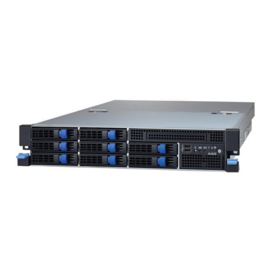
Page 26: About The Product
The following views show you the product. 1.5.1 System Front View Ears 3.5” /2.5” HDD bays USB Ports ID Button NMI Button RESET Button LAN1/LAN2/LAN3 ID LED System Fan Fail LED System Warning LED Power On/OFF Button with LED http://www.tyan.com... - Page 27 2 PSU and 2 PSU AC cords are Amber solid on connected. After system is powered on, disconnect 1 PSU AC cord. 2 PSU and 2 PSU AC cords are Amber solid on connected. After system is powered on, disconnect 1 PSU. http://www.tyan.com...
- Page 28 HDD LED HDD Status Status LED Activity LED Color: Amber Color: Green No Driver Present or power disconnected Driver Present No Activity Solid ON Access Activity Blinking HDD Fail Solid ON Rebuild Blinking @4Hz Identify (Locate the HDD) Blinking @1Hz http://www.tyan.com...
-
Page 29: System Rear View
Blinking Green Solid Green Active Solid Green Solid Yellow Link 1000 Mbps (1Gbps) Blinking Green Solid Yellow Active Solid Yellow Solid Yellow Link 10 Gbps Blinking Yellow Solid Yellow Active NOTE: “Left” and “Right” are viewed from the rear panel. http://www.tyan.com... - Page 30 When X540 LAN chip is on, LAN1 and LAN2 can support up to 100Mbps~10Gbps. Peripheral devices can be plugged straight into any of these ports but software may be required to complete the installation. ID LED Behavior Status Remark Color Normal ID LED Blue Local and Located Solid on remote http://www.tyan.com...
-
Page 31: Motherboard (S7056) Layout
The board you receive may not look exactly like the above diagram. The DIMM slot numbers shown above can be used as a reference when reviewing the DIMM population guidelines shown later in the manual. For the latest board revision, please visit our web site at http://www.tyan.com. http://www.tyan.com... -
Page 32: Jumpers & Connectors
ME Firmware Update Header IDLED_BTN ID LED Button ID_LED ID LED SATA0/SATA1 Serial ATA Connector J19/J20/J64/J65/J66 4-pin Fan Power Connector J45/J63 4-pin CPU1/CPU0 Fan Power Connector Jumper Legend OPEN - Jumper OFF Without jumper cover CLOSED - Jumper ON With jumper cover http://www.tyan.com... -
Page 33: System Block Diagram (S7056)
1.5.5 System Block Diagram (S7056) http://www.tyan.com... -
Page 34: Internal View
1.5.6 Internal View With Riser Card Brackets 3.5”/2.5” HDD cage (underneath) SAS/SATA HDD Backplane Board System Fan Unit Power Distribution Board PCI-E Riser Card Bracket Power Supply (underneath) http://www.tyan.com... - Page 35 Without Riser Card Brackets 3.5”/2.5” HDD cage (underneath) SAS/SATA HDD Backplane Board System Fan Unit Power Distribution Board Power Supply (underneath) http://www.tyan.com...
- Page 36 NOTE http://www.tyan.com...
-
Page 37: Chapter 2: Setting Up
Caution! To avoid damaging the motherboard and associated components, do not use torque force greater than 7kgf/cm (6.09 lb/in) on each mounting screw for motherboard installation. Do not apply power to the board if it has been damaged. http://www.tyan.com... -
Page 38: Precautions
Working on a system that is connected to a power supply can be extremely dangerous. Follow the guidelines below to avoid damage to GN70-B7056 or injury to yourself. Ground yourself properly before removing the top cover of the system. -
Page 39: Installing Motherboard Components
CPUs, memory modules, HDD and PCI-E cards. 2.1.1 Removing the Chassis Cover Follow these instructions to remove the GN70-B7056 chassis cover. Unscrew the rear top cover on the back side. Unscrew the front top cover and pull the latches aside to lift up the top cover. - Page 40 Slide the rear top cover out. http://www.tyan.com...
-
Page 41: Removing The Riser Card Brackets
2.1.2 Removing the Riser Card Brackets Follow these instructions to remove the PCI-E Riser Card Brackets. Loose three thumb screws to release the PCI-E Riser Card Brackets. Lift up the Riser Card Brackets. http://www.tyan.com... -
Page 42: Installing The Cpu And Heatsink
Locate the CPU sockets. Always start with CPU0 first. Pull the first and second levers slightly away from the socket and then push them to a fully open position. Push the CPU socket cover to a fully open position. Take out the protection http://www.tyan.com... - Page 43 Place the CPU into the socket and make sure that the gold arrow is located in the right direction. http://www.tyan.com...
- Page 44 Close the CPU socket cover and press the levers down to secure the CPU. Position the heatsink on top of the CPU and secure it with 4 screws. Repeat the procedures mentioned earlier to install the second CPU and heatsink. http://www.tyan.com...
-
Page 45: Installing The Memory
Align the memory module with the slot. When inserted properly, the memory slot locking levers lock automatically onto the indentations at the ends of the module. Follow the recommended memory population table to install the other memory modules. http://www.tyan.com... - Page 46 Memory Population Option Table The following pictures show common types of DDR3 memory modules. http://www.tyan.com...
- Page 47 DIMM per channel. 6. Always install with DIMM_A0 Slot first, following the alphabetical order (starting with DIMM_A0, DIMM_B0, DIMM_C0, DIMM_D0), and then the numerical order (starting with DIMM_A1, DIMM_B1, DIMM_C1, DIMM_D1, DIMM_A2, DIMM_B2, DIMM_C2, DIMM_D2). http://www.tyan.com...
- Page 48 DIMM per channel. 6. Always install with DIMM_A0 Slot first, following the alphabetical order (starting with DIMM_A0, DIMM_B0, DIMM_C0, DIMM_D0), and then the numerical order (starting with DIMM_A1, DIMM_B1, DIMM_C1, DIMM_D1, DIMM_A2, DIMM_B2, DIMM_C2, DIMM_D2). http://www.tyan.com...
- Page 49 Physical Ranks are used to calculate DIMM Capacity. Supported and validated DRAM Densities are 2Gb and 4Gb. Command Address Timing is 1N. The speeds are estimated targets and will be verified through simulation. DDP -Dual Die Package DRAM stacking. P –Planer monolithic DRAM Die. http://www.tyan.com...
- Page 50 QR RDIMM are supported but have not been validated by Intel/PMO in a homogenous environment. The coverage will have limited system level testing, no signal integrity testing, and no interoperability testing. All quad rank DIMMs that pass internal validation testing will be posted on http://www.tyan.com. http://www.tyan.com...
-
Page 51: Installing Hard Drives
2.1.4 Installing Hard Drives The GN70-B7056 can support up to eight (8) 3.5” or 2.5” hard drives. Follow these instructions to install a hard drive. Warning!!! Always install the hard disk drive to the chassis after the chassis is secured on the rack. - Page 52 Option A: for 2.5” hard drives Place a 2.5” hard drive into the HDD tray and use 4 screws to secure the HDD. Option B: for 3.5” hard drives Unscrew the drive bracket from the HDD tray. http://www.tyan.com...
- Page 53 Place a 3.5” hard drive into the drive tray and use 6 screws to secure the HDD. Reinsert the HDD tray into the chassis and press the locking lever to secure the tray. http://www.tyan.com...
-
Page 54: Installing The Pci-E Cards
2.1.5 Installing the PCI-E Cards The GN70-B7056 supports PCI-E Riser Card Brackets. A power cable (2x3p/2x4p) is required for GPU cards. Follow these instructions to install PCI-E cards. Unscrew the PCI-E slot to take out the PCI bracket. Insert the PCI-E card and securely screw as shown. - Page 55 Repeat the same procedures for the second Riser Card Bracket. http://www.tyan.com...
-
Page 56: Rack Mounting
CRAL-0190 Rail Kit Front view 2.2.1 Installing the Server in a Rack Follow these instructions to mount the TYAN GN70-B7056 into an industry standard 19” rack. NOTE: Before mounting the TYAN GN70-B7056 in a rack, ensure that all internal components have been installed and that the unit has been fully tested. However, to make the installation easier, we suggest that you remove all HDD trays before you insert the chassis to the rack. - Page 57 Repeat the same procedures for the front end of the rail. Front Push the locking latch to secure the rail to the rack. Repeat the same procedures for the other rail. Left Right http://www.tyan.com...
- Page 58 There are three holes on each rail which are used to hook and secure the chassis. Align the studs on the chassis with the holes on the rails and make sure the chassis is securely hooked. http://www.tyan.com...
- Page 59 Push the chassis back into the rack. The installation is now complete. http://www.tyan.com...
-
Page 60: Removing The Server From A Rack
2.2.2 Removing the Server from a Rack Follow these instructions to remove the TYAN GN70-B7056 from an industry standard 19” rack. Push the ears to pull the chassis forward. Push forward the locking tabs on both rails to unhook the chassis from the rails. -
Page 61: Chapter 3: Replacing Pre-Installed Components
This chapter explains how to replace the pre-installed components, including the S7056 Motherboard, M1709G70-FPB Front Panel Board, PCI-E Riser Card, M1245G70-BP6-8 SATA/SAS HDD Board, System Fan and Power Supply Unit etc. Disassembly Flowchart The following flowchart outlines the disassembly procedure. http://www.tyan.com... -
Page 62: Removing The Cover
Removing the Cover Before replacing any parts you must remove the chassis cover. Follow Section 2.1.1 Removing the Chassis Cover (page 39) to remove the cover of the GN70-B7056. Replacing Motherboard Components Follow these instructions to replace motherboard components, including the motherboard. - Page 63 Locate the PCH Upgrade ROM Header on your motherboard. Insert the Upgrade ROM Kit in the direction as the arrow shows. You have completed the PCH Upgrade ROM Kit installation. http://www.tyan.com...
-
Page 64: Replacing Pci-E Riser Card Cards
3.4.2 Replacing PCI-E Riser Card Cards The GN70-B7056 has pre-installed PCI-E×16 riser cards. Follow the instructions below to disassemble the M7056-L24-3F and M7056-R24-3F PCI-E riser cards. Unscrew to take out the PCI-E card. Unscrew the M7056-R24-3F riser card to replace a new one if necessary. - Page 65 Repeat the same procedures for the second Riser Card Bracket. Unscrew the M7056-L24-3F riser card to replace a new one if necessary. http://www.tyan.com...
-
Page 66: Disconnecting All Motherboard Cables
Before replacing the motherboard or certain components, remove cables connected to the motherboard. Follow these instructions to remove all cables. Disconnect the Fan control, PSMI and power cables. Disconnect the Mini SAS, USB and front panel cables. Disconnect the 2x4pin power cable. http://www.tyan.com... -
Page 67: Removing The Motherboard
After removing all of the aforementioned cables, follow the instructions below to remove the motherboard from the chassis. Remove the heatsinks and processors if installed. Remove the nine screws securing the motherboard to the chassis. Carefully lift the motherboard from the chassis. http://www.tyan.com... -
Page 68: Replacing The Power Distribution Board
Replacing the Power Distribution Board Follow these instructions to replace the M1601T70-D-PDB power distribution board. Disconnect all cables. Unscrew to replace a new power distribution board. http://www.tyan.com... -
Page 69: Replacing The Front Panel Board
Replacing the Front Panel Board Follow these instructions to replace the M1709G70-FPB Front Panel Board. Unscrew to release the Front Panel Board Module. Push the Front Panel Board Module forward. Disconnect the Front Panel Control and USB cables. http://www.tyan.com... - Page 70 Unscrew the Front Panel Board to replace a new one. Follow the steps described earlier in reverse to reinstall the Front Panel Board. http://www.tyan.com...
-
Page 71: Front Panel Board Specifications
HDD backplane board Power On/Off Button with LED: Green ID LED Color: Blue LEDs System Warning LED: Amber System Fan Fail LED: Red LAN1/LAN2/LAN3: Green RESET button ID button Push buttons Power On/Off button with LED NMI Button http://www.tyan.com... -
Page 72: Connector Pin Definition
Connector Pin Definition Front Panel Connector (J3) Definition Definition PW_LED+ ID_LED+ PW_LED- ID_LED- HD/LAN3_LED+ SYS_FAULT1- HD/LAN3_LED- SYS_FAULT2- PWR_SW+ LAN1_LED+ PWR_SW- LAN1_LED- RESET+ ICH_SMBDAT RESET- ICH_SMBCLK ID_SW+ INTRU# Temp_sensor LAN2_LED+ EXT_INT LAN2_LED- USB Connector (J1) Definition Definition USB1- USB2- USB1+ USB2+ http://www.tyan.com... -
Page 73: Replacing The System Fan
Replacing the System Fan Follow these instructions to replace the system fan. Press the latch in the direction as shown to lift up the fan from cage. Take out the fan unit. Loose the screws on both sides. http://www.tyan.com... - Page 74 Push the latch in the direction as the arrow shown to release the fan from the iron holder. Remove the iron holder to replace a new fan. After replacing a new one, put the fan unit back into the cage. http://www.tyan.com...
-
Page 75: Replacing The Fan Backplane Board
Follow these instructions to replace the M1806G70-FB Fan Backplane Board in your system. Press the latch in the direction as shown to lift up the fan from cage. Remove all four fans from the chassis. Disconnect all cables attached to the Fan Backplane Board. http://www.tyan.com... - Page 76 Use a screw driver to unscrew the Fan Module. Disconnect the power and fan cables. Lift up the Fan Module. http://www.tyan.com...
- Page 77 Release the 14 screws on the Fan Backplane Board to replace a new one. Follow the steps described in reverse order to reinstall the fan cage. http://www.tyan.com...
-
Page 78: Fan Bp Board Specifications
254 mm x 82 mm, 4-layer PCB (2) 1x4pin R/A Power Connector (8) 2x2pin Fan Connectors Integrated I/O (1) 2x10pin Barebone Fan Connector (1) 2x2pin Connector for S7015 3.8.2 Fan BP Board LED Definitions FAN Status Green LED Red LED With Fan Without Fan http://www.tyan.com... -
Page 79: Connector Pin Definitions
3.8.3 Connector Pin Definitions Power Connector (PW1/PW2) Definition Definition +12V Barebone Fan Connector (J9) Definition Definition FANIN1 FANIN6 FANIN2 FANIN7 FANIN3 FANIN8 FANIN4 SIO_FANIN1 FANIN5 SIO_ FANIN2 MB_PWM2 MB_PWM1 SIO_ FANIN3 SMBUS_3V3_DATA SIO_ FANIN4 SMBUS_3V3_CLK VDD_3.3_AUX MB_PWM3 http://www.tyan.com... -
Page 80: Replacing The Hdd Backplane Board
Fan Module. Disconnect the power cables attached to the HDD BP Board. Unscrew the HDD BP Board. Remove the HDD BP Board from the hook. Replace a new HDD BP Board and reinstall it into the chassis following the steps in reverse. http://www.tyan.com... -
Page 81: Hdd Bp Board Specifications
(8) SAS HDD Connectors Integrated I/O (2) Mini SAS Connectors to MB and RAID Card (1) 2 x 4-pin Power Connector 8 HDD active LEDs LEDs 8 HDD fault LEDs PW3 Pin definition Definition Definition +12V +12V +12V +12V http://www.tyan.com... -
Page 82: Replacing The Power Supply
Follow these instructions to replace the power supply units. Press and hold the latch to pull the power supply out. After replacing a new power supply, press and hold the latch to push the power supply back into the chassis. http://www.tyan.com... -
Page 83: Appendix I: Cable Connection Tables
Connects to Motherboard M1601T70-D-PDB PW1 (MB) PATX1 (MB1) PATX2 (MB2) J7 (PSMI) Power Board FAN Board Connects to M1601T70-D-PDB M1806G70-FB PW4 (FAN BD1) PW5 (FAN BD2) Power Board SAS/SATA Backplane Connects to M1601T70-D-PDB M1245G70-BP6-8 PATX6 (HDD BP1) PATX7 (HDD BP2) http://www.tyan.com... - Page 84 NOTE http://www.tyan.com...
-
Page 85: Appendix Ii: Fru Parts Table
PCI-E x16 2U Riser Card PCBA M7056-L24-3F 412100000213 PCI-E x16 2U Riser Card Rack CRAL-0190 452T44600001 Slide Rail Kit Mounting A/C power cord, L=1830mm, EU CCBL-0300 332810000281 type Power cord; US, 125V, 18AWGX3C, Cable CCBL-0317 332810000397 L:1800mm CCBL-0689 422797800004 Mini-SAS to Mini-SAS, L=500mm http://www.tyan.com... - Page 86 NOTE http://www.tyan.com...
-
Page 87: Appendix Iii: Fan And Temp Sensors
SYS_FAN_1, SYS_FAN_2, SYS_FAN_3 and SYS_FAN_4. They detect the fan speed (rpm) Temp Sensor: PCH_Area_Temp, LAN_Temp and M/B_Inlet_Temp. They detect the system temperature around. NOTE: The system temperature is measured in a scale defined by Intel, not in Fahrenheit or Celsius. http://www.tyan.com... - Page 88 BIOS Temp Sensor Name Explanation: http://www.tyan.com...
- Page 89 Temperature of CPU0 DIMM A1 Slot CPU0_DIMM_B0 Temperature of CPU0 DIMM B0 Slot CPU0_DIMM_B1 Temperature of CPU0 DIMM B1 Slot CPU0_DIMM_C0 Temperature of CPU0 DIMM C0 Slot CPU0_DIMM_C1 Temperature of CPU0 DIMM C1 Slot CPU0_DIMM_D0 Temperature of CPU0 DIMM D0 Slot http://www.tyan.com...
- Page 90 Fan speed of SYS_FAN_3 SYS_FAN_4 Fan speed of SYS_FAN_4 SYS_FAN_5 Fan speed of SYS_FAN_5 SYS_FAN_6 Fan speed of SYS_FAN_6 SYS_FAN_7 Fan speed of SYS_FAN_7 SYS_FAN_8 Fan speed of SYS_FAN_8 PSU1_Fan Fan speed of PSU1 PSU2_Fan Fan speed of PSU2 http://www.tyan.com...
-
Page 91: Appendix Iv: Technical Support
By offering plenty of options for users, MiTAC serves multiple market segments with the industry’s most competitive services to support them. Please feel free to contact us directly for this service at tech-support@tyan.com Help Resources: 1. See the beep codes section of this manual. - Page 92 (RMA) number. The RMA number should be prominently displayed on the outside of the shipping carton and the package should be mailed prepaid. TYAN will pay to have the board shipped back to you. TYAN® GN70-B7056 Service Engineer’s Manual V1.0 Document No.: D2159-100 http://www.tyan.com...
Need help?
Do you have a question about the GN70-B7056 and is the answer not in the manual?
Questions and answers