Table of Contents
Advertisement
Quick Links
Advertisement
Table of Contents

Subscribe to Our Youtube Channel
Related Manuals for TYAN GC68-B8036


Summary of Contents for TYAN GC68-B8036
- Page 1 GC68-B8036/ GC68A-B8036 Service Engineer’s Manual http://www.tyan.com...
- Page 2 http://www.tyan.com...
- Page 3 MITAC assumes no liability whatsoever, and ® disclaims any express or implied warranty, relating to sale and/or use of TYAN products including liability or warranties relating to fitness for a particular purpose or merchantability. MITAC retains the right to make changes to produce descriptions and/or specifications at any time, without notice.
- Page 4 This Class A digital apparatus complies with Canadian ICES-003. Cet appareil numérique de la Classe A est conforme à la norme NMB-003 du Canada. Notice for Europe (CE Mark) ● This product is in conformity with the Council Directive 2014/30/EU and 2014/35/EU. http://www.tyan.com...
- Page 5 Replace only with the same or equivalent type recommended by manufacturer. Dispose of used battery according to manufacturer instructions and in accordance with your local regulations. VCCI-A ● この装置は、クラスA機器です。この装置を住宅環境で使用すると電波妨害を引き 起こすことがあります。この場合には使用者が適切な対策を講ずるよう要求される VCCI-A ことがあります。 Safety: IEC/EN 62368-1 ● This equipment is compliant with CB/LVD of Safety: IEC/EN 62368-1. http://www.tyan.com...
- Page 6 This manual is intended for skilled person with hardware knowledge of computers. Components inside the compartments should be serviced only by a skilled person. This manual is aimed to provide you with instructions on installing your TYAN GC68-B8036. How this guide is organized...
- Page 7 Safety and Compliance Information Before installing and using TYAN GC68-B8036, take note of the following precautions: ·Read all instructions carefully. ·Do not place the unit on an unstable surface, cart, or stand. ·Do not block the slots and opening on the unit, which are provided for ventilation.
- Page 8 You must become familiar with the safety information in this guide before you install, operate, or service TYAN products. Symbols on Equipment Caution. This symbol indicates a potential hazard.
- Page 9 · Do not attempt to move a fully loaded rack. Remove equipment from the rack before moving it. · Do not attempt to move a rack on an incline that is greater than 10 degrees http://www.tyan.com...
- Page 10 This will reduce the risk of personal injury, fire, or damage to the equipment. The total rack load should not exceed 80 percent of the branch circuit rating. Consult the electrical authority having jurisdiction over your facility wiring and installation requirements. http://www.tyan.com...
- Page 11 TYAN, your authorized TYAN partner, or their agents. Equipment Modifications · Do not make mechanical modifications to the system. TYAN is not responsible for the regulatory compliance of TYAN equipment that has been http://www.tyan.com...
- Page 12 – The product does not operate normally when you follow the operating instructions. · Retain all screws or other fasteners when removing access cover(s). Upon completion of accessing inside the product, refasten access cover with original screws or fasteners. http://www.tyan.com...
-
Page 13: Table Of Contents
Table of Contents Chapter 1: Overview............... 15 About the TYAN GC68-B8036 ..........15 Product Models ............... 16 Features .................. 17 Standard Parts List ..............27 1.4.1 Box Contents and Accessories ........27 About the Product ..............28 ... - Page 14 Appendix II: Installing IO Plate for OCP Card ......93 Appendix III: Cable Connection Tables ........95 Appendix IV: Fan and Temp Sensors ........... 99 Appendix V: FRU Parts Table ............103 Appendix VI: Technical Support ..........105 http://www.tyan.com...
-
Page 15: Chapter 1: Overview
IT demand but also offers a smooth path for future application usage. TYAN® also offers GC68A-B8036 in a version that supports up to 12 hot-swappable 2.5” NVMe U.2 devices with (4) SATA 6G/SAS 12G option, while GC68-B8036 supports 4 hot-swappable 2.5"... -
Page 16: Product Models
Product Models The system board within the Tyan Barebone is defined by the following models: B8036G68AE12HR: Single-socket AMD EPYC 7002 barebone platform with (12) tool-less, hot-swappable 2.5” drive trays supports (8) NVMe U.2 devices and (4) NVMe/SATA 6G/SAS12G devices ... -
Page 17: Features
Interface (12) NVMe The SAS/SATA HDD backplane is connected to onboard SATA connection by default. Please *Notification contact Tyan technical support if a discrete SAS HBA/RAID adapter is required. System Cooling (6) 4028 fans + tailored air duct Configuration pre-installed... - Page 18 8 Channels per CPU Memory voltage 1.2V (1) FH/HL + (1) HH/HL PCI-E Gen4 PCI-E (1) M8036-R16-1F for (1) FH/HL Pre-install TYAN PCI-E Gen 4 x16 slot (Right), (1) Riser Card M8036-L16-1F for (1) HH/HL PCI-E Expansion Slots (PCI-E Gen4)
- Page 19 Class A CE (DoC) Class A Regulation CB/LVD Class A VCCI Class A Operating Temp. 10° C ~ 35° C (50° F~ 95° F) Operating Environment Non-operating Temp. - 40° C ~ 70° C (-40° F ~ 158° F) http://www.tyan.com...
- Page 20 Interface (2) NVMe The SAS/SATA HDD backplane is connected to onboard SATA connection by default. Please *Notification contact Tyan technical support if a discrete SAS HBA/RAID adapter is required. System Cooling (6) 4028 fans + tailored air duct Configuration pre-installed...
- Page 21 8 Channels per CPU Memory voltage 1.2V (1) FH/HL + (1) HH/HL PCI-E Gen4 PCI-E (1) M8036-R16-1F for (1) FH/HL Pre-install TYAN PCI-E Gen 4 x16 slot (Right), (1) Riser Card M8036-L16-1F for (1) HH/HL PCI-E Expansion Slots (PCI-E Gen4)
- Page 22 (BMC), Feature 10/100/1000 Mb/s MAC interface Brand / ROM size AMI, 32MB Hardware Monitor, SMBIOS 3.0/PnP/Wake on LAN, Boot from BIOS USB device/PXE via LAN/Storage, Feature Console Redirection, ACPI 6.1, ACPI sleeping states S0, S5, FAN speed control automatic http://www.tyan.com...
- Page 23 Humidity RoHS RoHS 6/6 Compliant Barebone (1) GC68A-B8036 Barebone Package Contains Manual (1) Quick Installation Guide GC68-B8036 (B8036G68V4E4HR-LE) Form Factor 1U Rackmount Chassis Model GC68 Dimension (D x W x 26.77" x 17.26" x 1.69" (680 x 438.5 x 43mm)
- Page 24 Tyan technical support if a discrete SAS HBA/RAID adapter is required. System Cooling (6) 4028 fans + tailored air duct Configuration pre-installed Type RPSU Input Range AC 100~240V/ 12~6A Frequency 50-60 Hz Power Supply Output Watts 850 Watts Efficiency...
- Page 25 Onboard Chipset Onboard Aspeed AST2500 24-bit high quality video AST2500 iKVM compression, Supports storage over Feature IP and remote platform-flash, USB Server Management 2.0 virtual hub IPMI 2.0 compliant baseboard AST2500 IPMI management controller (BMC), Feature 10/100/1000 Mb/s MAC interface http://www.tyan.com...
- Page 26 In/Non-operating 90%, non-condensing at 35° C Humidity RoHS RoHS 6/6 Compliant Barebone (1) GC68-B8036 Barebone Package Contains Manual (1) Quick Installation Guide NOTE: 1. The specifications are subject to change without prior notice. 2. Please visit our Web site for the latest specifications.
-
Page 27: Standard Parts List
Standard Parts List This section describes GC68-B8036 package contents and accessories. Open the box carefully and ensure that all components are present and undamaged. The product should arrive packaged as illustrated below. 1.4.1 Box Contents and Accessories If any items are missing or appear damaged, contact your retailer or browse to TYAN’s website for service:... -
Page 28: About The Product
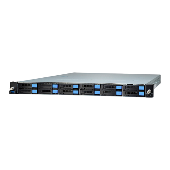
About the Product The following views show you the product. 1.5.1 System Front View GC68A-B8036 (B8036G68AV10E2HR-LE) GC68A-B8036 (B8036G68AE12HR) GC68-B8036 (B8036G68V4E4HR-LE) Description Description USB3.0 Port (M1725G68-USB Power Button with green & red pre-installed) Drive Trays ID Button with blue LED http://www.tyan.com... - Page 29 Status LED (Red) Drive present, no activity Green Solid On Drive present with activity Green Blinking Drive Fail Don’t care Red Solid On Drive identify Don’t care Red Blinking @ 1Hz Drive Rebuild Don’t care Red Blinking @ 4Hz http://www.tyan.com...
-
Page 30: System Rear View
Serial Port (COM1) LAN2 LAN3 OCP Card Area ID LED ID Button Expansion Slots (Half-height / Half-length PCI-E Gen.4 x16 card w/ tall bracket x2) Rear Panel LED Indication Color Behavior ID LED Blue Remote located / Blue Sold On http://www.tyan.com... -
Page 31: Psu And Lan Led Indications
Green Solid On Green Solid On 100 Mbps Active Green Blinking Green Solid On Link Green Solid On Amber Solid On 1000 Mbps (1Gbps) Active Green Blinking Amber Solid On NOTE: “Left” and “Right” are viewed from the rear panel. http://www.tyan.com... -
Page 32: System Top View
System Fans Riser Card Bracket M1631G68-D-PDB (M8036-R16-1F & M8036-L16-1F (pre-installed) pre-installed) *NOTE: 1. M1312G68-BP6E-4 & M1312G68-BP12-4 Drive Backplane Boards pre-installed on B8036G68V4E4HR-LE SKU 2. M1303G68A-BP12E-12 Drive Backplane Board pre-installed on B8036G68AV10E2HR-LE SKU 3. M1299G68A-BPE-12 Drive Backplane Board pre-installed on B8036G68AE12HR http://www.tyan.com... -
Page 33: Chassis Dimensions
1.5.5 Chassis Dimensions http://www.tyan.com... -
Page 34: Block Diagram (S8036)
1.5.6 Block Diagram (S8036) http://www.tyan.com... -
Page 35: Board Image (S8036)
1.5.7 Board Image (S8036) NOTE: Please refer to Tyan S8036 User Guide for more MB details. http://www.tyan.com... - Page 36 NOTE http://www.tyan.com...
-
Page 37: Chapter 2: Setting Up
Caution! To avoid damaging the motherboard and associated components, use torque force within the range kgf/cm (4.35 ~ 6.09 lb/in) on each mounting screw for motherboard installation. Do not apply power to the board if it has been damaged. http://www.tyan.com... -
Page 38: Precautions
Working on a system that is connected to a power supply can be extremely dangerous. Follow the guidelines below to avoid damage to GC68-B8036 or injury to yourself. Ground yourself properly before removing the top cover of the system. -
Page 39: Installing Motherboard Components
This section describes how to install components on to the motherboard, including CPUs, memory modules and Add-on cards. 2.1.1 Removing the Chassis Cover Follow these instructions to remove the GC68-B8036 chassis cover. 1. Use a screw driver to loosen the screw. 2. Pull up the latch and slide it backwards. http://www.tyan.com... - Page 40 3. Slide to lift up the rear top cover. 4. Slide out the drive trays. Unscrew the front top cover and then slide it forwards to lift it up. http://www.tyan.com...
-
Page 41: Replacing The Chassis Cover
2.1.2 Replacing the Chassis Cover Follow these instructions to replace the GC68-B8036 chassis cover. Place the front top cover on the chassis and slide it backwards. Secure the front top cover with two screws and then insert the HDD drives into the chassis. - Page 42 Use a screw driver to fasten the rear top cover. http://www.tyan.com...
-
Page 43: Installing The Cpu And Heat Sink
2.1.3 Installing the CPU and Heat sink Follow the steps below on installing CPU and CPU heat sink. The GC68-B8036 supports single AMD Socket SP3. The following installation is based on an AMD Socket SP3. 1. Use a T20 Torx screwdriver to loosen the screws securing the force frame in a sequential order (3->2->1). - Page 44 4. Align and install the carrier frame with package into the slot on the rail frame. 5. Using your thumbs and forefinger, remove the PnP cap by lifting it up vertically. Carefully close the rail frame with the installed package. Then push both edges of the rail frame firmly until it locks in place. http://www.tyan.com...
- Page 45 6. Close the force frame. Then use a T20 Torx screwdriver to tighten the screws to secure the force frame in a sequential order (1 ->2->3). 7. Place a heatsink on top of the processor. Use a T20 Torx screwdriver to tighten four screws in a diagonal sequence to secure the heat sink. http://www.tyan.com...
-
Page 46: Installing The Memory
Press the memory slot locking levers in the direction of the arrows as shown in the following illustration. Align the memory module with the slot. When inserted properly, the memory slot locking levers lock automatically onto the indentations at the ends of the module. http://www.tyan.com... - Page 47 Memory Population table http://www.tyan.com...
- Page 48 D-R,LR, or 3DS DIMM type Populating NVDIMMs with capacity-2x D RDIMMs or capacity LRDIMMs Table2.RDIMM Max Freq Support SP3 Package Motherboard Type1 Slots DIMMs DIMM Frequency(MT/s) Populated 1.2V 3200 3200 3200 3200 2933 2933 2933 http://www.tyan.com...
-
Page 49: Installing The Expansion Card
2.1.5 Installing the Expansion Card Follow these instructions to install the expansion card. Loosen two screws to take out the riser card bracket. Unscrew to remove the dummy bracket. http://www.tyan.com... - Page 50 Insert the expansion card into the riser card bracket and secure with a screw. Replace the Riser Card Bracket into the chassis. http://www.tyan.com...
-
Page 51: Installing The 2.5" Hard Drive
Follow these instructions to install the 2.5” hard drives for B8036G68AV10E2HR-LE & B8036G68AE12HR SKU. 1. Press the locking tab to pull the lever open. 2. Slide the drive tray out. 3. Press the locking tab to pull the tray side rail open. http://www.tyan.com... - Page 52 4. Align the hard drive with the guide pins and install the hard drive into the drive tray. Close the tray side rail. http://www.tyan.com...
- Page 53 5. Insert the drive tray into the chassis and close the lever. http://www.tyan.com...
-
Page 54: Installing The Slim 2.5" Hard Drives
Follow these instructions to install the slim 2.5” hard drives for B8036G68V4E4HR-LE SKU. 1. Press the locking tab to pull the lever open. 2. Slide the drive tray out. 3. Align the hard drive with the guide pins and install the hard drive into the drive tray. http://www.tyan.com... - Page 55 4. Insert the drive tray into the chassis and close the lever. http://www.tyan.com...
-
Page 56: Installing The 3.5" Hard Drives
2.1.8 Installing the 3.5” Hard Drives Follow these instructions to install the 3.5” hard drives for B8036G68V4E4HR-LE SKU. 1. Press the locking tab to pull the lever open. 2. Slide the drive tray out. http://www.tyan.com... - Page 57 3. Pull the tray side rail open. 4. Align the hard drive with the guide pins and install the hard drive into the drive tray. Close the tray side rail. 5. Insert the drive tray into the chassis and close the lever. http://www.tyan.com...
-
Page 58: Installing The Micro Sd Card
Installing the Micro SD Card Follow these instructions to install the Micro SD Card. 1. Open the protection cap. 2. Insert the Micro SD Card into the slot and close the cap. 3. Slide the protection cap slightly forwards to lock. http://www.tyan.com... -
Page 59: Installing The M.2 Latch
Follow these instructions to install the M.2 Latch. 1. Take out the M.2 Latch from the AK box. 2. Measure the length of the M.2 card and insert the latch into the appropriate hole. 3. Turn the M.2 Latch 90 to the right. http://www.tyan.com... - Page 60 4. Insert the M.2 card into the slot. Pull the latch to lock the M.2 card. http://www.tyan.com...
-
Page 61: Rack Mounting
Rails x 2 Screw Sacks x 2 2.2.1 Installing the Server in a Rack Follow these instructions to mount the GC68-B8036 into an industry standard 19” rack. Note: Before mounting GC68-B8036 in a rack, ensure that all internal components have been installed and that the unit has been fully tested. -
Page 62: Installing Slide Rails To The Rack
Take out the rails from the accessory kit. Push the white tab in the direction as the arrow shows to draw out the inner rail. Attach the inner rails to both sides of the chassis. Push the inner rails backward to lock in place. http://www.tyan.com... - Page 63 Attach the outer rail to the rack. Pull the latch open and align the square stud with the square hole on the rack rail. Please note that the square stud must be fully attached inside the square hole and then close the latch to lock. Rear http://www.tyan.com...
- Page 64 Front http://www.tyan.com...
-
Page 65: Rack Mounting The Server
Must be done with at least 2 people. Properly place the chassis directly on the rack and install. Slide in the chassis half way to the lock position. Push the blue tabs simultaneously to slide the chassis all in. http://www.tyan.com... - Page 66 Fasten the chassis ear to the front surface of chassis. http://www.tyan.com...
-
Page 67: Removing The Server From Rack
Pull out the chassis half way to the lock position. Push the white locking tabs forward to slide the chassis all out from the rack. Caution: Remove the server from the rack carefully. Must be done with at least 2 people. http://www.tyan.com... - Page 68 NOTE http://www.tyan.com...
-
Page 69: Chapter 3: Replacing Pre-Installed Components
This chapter explains how to replace the pre-installed components, including the S8036 Motherboard, M1724G68-FPB Front Panel Board, M8036-L16-1F M8036-R16-1F Riser Cards, 4 HDD Backplane Boards, M1631G68-D-PDB Power Distribution Board, System Fan and Power Supply etc. Disassembly Flowchart The following flowchart outlines the disassembly procedure. http://www.tyan.com... -
Page 70: Removing The Cover
Removing the Cover Follow Chapter 2.1.1 to remove the cover of GC68-B8036. Replacing the Power Supply To replace the power supply follow these instructions. Press the latch as shown to pull out the power supply module. Replace a new single power and reinsert it into the power cage following the above steps in reverse. -
Page 71: Replacing The Front Panel Board
2. Loosen 2 screws to remove the front panel cage and bracket. 3. Disconnect the cable and unscrew the Front Panel Board. 4. After replacing with a new Front Panel Board, follow the steps described earlier in reverse order to reinstall the front panel bezel. http://www.tyan.com... -
Page 72: Front Panel Board Features
3.5.1 Front Panel Board Features Front View Rear View M1724G68-FPB Front Panel Board Form Factor 33.5*21*1.6 mm (1) Signal Connector (J1) Integrated I/O (1) PWR Button (1) ID Button http://www.tyan.com... -
Page 73: Replacing The Usb Board
2. Loosen 2 screws to remove the USB cage and bracket. 3. Disconnect the cable and unscrew the USB Board. 4. After replacing with a new USB Board, follow the steps described earlier in reverse order to reinstall the front USB bezel. http://www.tyan.com... -
Page 74: Usb Board Features
3.6.1 USB Board Features Front View Rear View M1725G68-USB Front Panel Board Form Factor 31.9*19.4*1.6 mm (1) Signal Connector (J2) Integrated I/O (1) USB3.0 Connector http://www.tyan.com... -
Page 75: Replacing The Hdd Backplane Board
Follow these instructions to replace the HDD Backplane Boards. B8036G68V4E4HR-LE SKU (M1312G68-BP6E-4 & M1302G68-BP12-4 pre-installed) 1. Slide out the hard drive trays and disconnect all cables connected to the M1312G68-BP6E-4 HDD Backplane Board. 2. Unscrew to remove the M1312G68-BP6E-4 HDD BP Board. http://www.tyan.com... - Page 76 Use a screw driver to loosen two screws. 4. Lift up the M1302G68-BP12-4 HDD Backplane Board to get off the hook. 5. After replacing with new HDD Backplane Boards, follow the procedures described earlier in reverse order to reinsert the HDD Backplane Board into the chassis. http://www.tyan.com...
- Page 77 HDD Backplane Board. 3. Lift up the HDD Backplane Board to get off the hook. 4. After replacing with new HDD Backplane Boards, follow the procedures described earlier in reverse order to reinsert the HDD Backplane Board into the chassis. http://www.tyan.com...
-
Page 78: Hdd Bp Board Features
Form Factor 435*38.3*2.6 mm PCI-EGen3 12-pot NVMe U.2 BP Board (12) Hot-swap 2.5” NVMe U.2 SSD (2) ATX 2x4-pin Power Connector Integrated I/O (2) 5V connector for DOM (6) Slim-SAS connector (8) Fan connector (1) 2x15-pin Fan Control Connector (J31) http://www.tyan.com... - Page 79 (2) Hot-swap 2.5” SAS 12G / SATA 6G & NVMe devices +(10) Hot-swap 2.5” SAS 12G / SATA 6G HDD/SSD (2) ATX 2x4-pin Power Connector Integrated I/O (2) 5V Connector for DOM (3) Mini-SAS HD Connector (1) Slim-SAS Connector (8) Fan Connector (1) 2x15-pin Fan Control Connector (J31) http://www.tyan.com...
- Page 80 PCI-EGen3 4-port 3.5”/2.5” HDD BP Board, supports 4x SATA 6G/s & SAS 12Gb/s (1) Big 4-pin Power Connector (PW2) Integrated I/O (1) ATX 4x2-pin Power Connector (J30) (1) Mini-SAS HD Connector (6) Fan Connector (1) 2x15-pin Fan Control Connector (J31) http://www.tyan.com...
- Page 81 (for B8036G68V4E4HR-LE SKU) Form Factor 303*40.1*1.6 mm PCI-EGen3 4-port 2.5” slim HDD BP Board (4) Hot-swap slim SATA 6Gb/s SSD or (4) hot-swap slim 2.5” NVMe U.2 Integrated I/O (1) ATX 8-pin Power Connector (J1) (4) OCULink Connector (4) SATA Connector http://www.tyan.com...
-
Page 82: Replacing Power Distribution Board
1. Pull the power supply modules slightly away from the chassis. Release the cable tie and disconnect all cables on the Power Distribution Board. 2. Unscrew to replace the M1631G68-D-PDB Power Distribution Board. 3. Follow the steps described earlier in reverse order to reinstall the power distribution board into the chassis. http://www.tyan.com... -
Page 83: Power Distribution Board Features
3.7.1 Power Distribution Board Features M1631G68-D-PDB Power Distribution Board Form Factor 171*108*1.6 mm (1) ATX24P (2) ATX8P (1) HDD 4P PWR Specifications (2) DOM 5V PWR (1) PMBUS (2) Micro ATX8P http://www.tyan.com... -
Page 84: Connector Definitions
3.7.2 Connector Definitions Location Definition Power supply slot Power supply slot PWR1 ATX Power 12x2 ATX Power 4x2 ATX Power 4x2 HDD Power 4x1 Micro ATX Power 4x2 Micro ATX Power 4x2 PMBUS DOM_5V_PW1 DOM Power DOM_5V_PW2 DOM Power http://www.tyan.com... -
Page 85: Replacing The Riser Card
1. Lift up the Riser Card Bracket from the chassis. Unscrew to replace with a new riser card M8036-L16-1F. 2. Unscrew to replace with a new riser card M8036-R16-1F. 3. Follow the steps described earlier in reverse order to reinstall the riser card bracket into the chassis. http://www.tyan.com... -
Page 86: Riser Card Features
PCI-E x16 Gen3 adapter card Specification (1) PCI-E x16 Gen3 slot support (1) PCI-E x16 Add-on card M8036-R16-1F Riser Card Form Factor 123.2*29.58*1.6 mm PCI-E x16 Gen3 adapter card Specification (1) PCI-E x16 Gen3 slot support (1) PCI-E x16 Add-on card http://www.tyan.com... -
Page 87: Replacing The Fan
1. Release the cable tie and then disconnect the fan cable. 2. Lift up the fan module from the chassis. 3. Release the rubber screws and push pins from the fan module. Replace with a new fan and then insert the rubber screws and push pins. http://www.tyan.com... - Page 88 4. Place the new fan module into the chassis and reconnect the fan cable. Remember to tie cables after fan replacement. http://www.tyan.com...
-
Page 89: 3.10 Replacing The Motherboard
3.10 Replacing the Motherboard After removing all of the aforementioned components, follow these instructions to remove the motherboard from the chassis. Release the cable tie and disconnect all MB cables. http://www.tyan.com... - Page 90 Unscrew the motherboard to lift it up for replacement. http://www.tyan.com...
-
Page 91: Appendix I: How To Recover Uefi Bios
UEFI recovery bootloader that would prevent the recovery process itself from working. In no event shall Tyan be liable for direct, indirect, incidental, special or consequential damages arising from the BIOS update or recovery. - Page 92 “Flash update completed. Press any key to reset the system” displayed on screen. Remove the USB disk and reboot. If your system does not have video output or the POST code halts at “FF” on the right-lower portion of the screen, please contact Tyan representatives for RMA service. http://www.tyan.com...
-
Page 93: Appendix Ii: Installing Io Plate For Ocp Card
2. Take out the IO plate for LAN card. Use a screwdriver to break the LAN port’s semi-shearing. Break one semi-shearing if a single-port LAN card is installed. Break both for a dual-port LAN card. SFP I/O Plate LAN I/O Plate http://www.tyan.com... - Page 94 3. Insert the IO Plate to the OCP card LAN port. Screw the IO Plate to the chassis. 4. Insert the LAN card into the OCP slot and secure the LAN card to the chassis with four screws. http://www.tyan.com...
-
Page 95: Appendix Iii: Cable Connection Tables
USB Panel Board to S8036 (MB) for all Series S8036GM2NE-LE M1725G68-USB Connect to S8036GM2NE USB 3.0 → USB3_FPIO1 4. Fan Ctrl Cable BP to S8036 (MB) for all Series M1302G68-BP12-4 S8036GM2NE-LE M1303G68A-BP12E-12 Connect to S8036GM2NE M1299G68A-BPE-12 FAN CTRL → FAN_HD1 5. Power Cable http://www.tyan.com... - Page 96 Power Board (PDB) to BP for B8036G68AV10E2HR-LE M1631G68-D-32A- M1303G68A-BP12E- Connect to (2)2*4P Micro-Fit → (2)1*2P Micro-Fit DOM_5V-PW1 DOM_5V-PW1 → DOM_5V-PW2 DOM_5V-PW2 Power Board (PDB) to BP for B8036G68AE12HR M1631G68-D-32A- Connect to M1299G68A-BPE-12 (2)2*4P Micro-Fit → (2)1*2P Micro-Fit DOM_5V-PW1 DOM_5V-PW1 → DOM_5V-PW2 DOM_5V-PW2 http://www.tyan.com...
- Page 97 SATADOM2/ 4*SATA SATA3/SATA4 Slim-SAS 8i NVME01 Slim SAS3 → → Slim-SAS 8i NVME23 Slim SAS4 → Slim-SAS 8i NVME45 Slim SAS5 → Slim-SAS 8i NVME67 Slim SAS7 → Slim-SAS 8i NVME89 Slim SAS6 → Slim-SAS 8i NVME1011 Slim SAS8 http://www.tyan.com...
- Page 98 Connect to S8036GM2NE-LE Mini-SAS HD to → HDR_4 4*SATA S8036 BP to (MB) for B8036G68AV10E2HR-LE M1303G68A-BP1 Connect to S8036GM2NE-LE 2E-12 NVME SIGNAL HDR1 → HDR_4 S8036 BP to (MB) for B8036G68AE12HR M1299G68A-BPE- Connect to S8036GM2NE → NVME SIGNAL HDR1 HDR_4 http://www.tyan.com...
-
Page 99: Appendix Iv: Fan And Temp Sensors
The red dot indicates the sensor. Fan and Temp Sensor Location: Fan Sensor: It is located in the third pin of the fan connector, which detects the fan speed (rpm) Temp Sensor: refer to Figure 1: Sensor Location. They detect the system temperature around. http://www.tyan.com... - Page 100 BIOS Temp Sensor Name Explanation: http://www.tyan.com...
- Page 101 The highest temperature of CPU0 D3 UMC0 channel E slot P0_D3_UMC1_CH_F The highest temperature of CPU0 D3 UMC1 channel F slot P0_D2_UMC1_CH_G The highest temperature of CPU0 D2 UMC1 channel G slot P0_D2_UMC0_CH_H The highest temperature of CPU0 D2 UMC0 channel H slot http://www.tyan.com...
- Page 102 Fan speed of SYS_FAN_5 SYS_FAN_6 Fan speed of SYS_FAN_6 SYS_FAN_7 Fan speed of SYS_FAN_7 SYS_FAN_8 Fan speed of SYS_FAN_8 SYS_FAN_9 Fan speed of SYS_FAN_9 SYS_FAN_10 Fan speed of SYS_FAN_10 SYS_FAN_11 Fan speed of SYS_FAN_11 SYS_FAN_12 Fan speed of SYS_FAN_12 http://www.tyan.com...
-
Page 103: Appendix V: Fru Parts Table
Appendix V: FRU Parts Table GC68-B8036/GC68A-B8036 FRU Parts Item Model Number Part Number Picture Description Power FRU-PS-0360 471100000414 850 W,DELTA,DPS-850AB-5 C Supply 12V, 31000 RPM,40*40*28mm,4 PIN FRU-TS-0270 422T60300001 (HEADER2*4) Heatsink FRU-TH-0310 343T60900003 1U-PASSIVE HEATSINK,w/screw Airduct FRU-TA-0210 Airduct for CPU 346T60300006... - Page 104 GC68-B8036/GC68A-B8036 FRU Parts 350mm, SlimSAS 8i 74P to SlimSAS 8i FRU-CS-1330 422T61600001 74P cable for B8036G68AE12HR 250mm, SlimSAS 8i 74P to SlimSAS 8i FRU-CS-1640 422T61600021 74P cable for B8036G68AE12HR 450mm, SlimSAS 8i 74P to SlimSAS 8i FRU-CS-1340 422T61600002 74P cable for B8036G68AE12HR...
-
Page 105: Appendix Vi: Technical Support
MITAC serves multiple market segments with the industry’s most competitive services to support them. Please feel free to contact us directly for this service at tech-support@tyan.com Help Resources: 1. See the beep codes section of this manual. - Page 106 (RMA) number. The RMA number should be prominently displayed on the outside of the shipping carton and the package should be mailed prepaid. TYAN will pay to have the board shipped back to you. TYAN® GC68-B8036 Service Engineer’s Manual V1.0a Document No.: D2506-100...
Need help?
Do you have a question about the GC68-B8036 and is the answer not in the manual?
Questions and answers