Table of Contents
Advertisement
Quick Links
Advertisement
Table of Contents

Related Manuals for TYAN GT24-B7066


Summary of Contents for TYAN GT24-B7066
- Page 1 GT24-B7066 Service Engineer’s Manual http://www.tyan.com...
- Page 2 http://www.tyan.com...
- Page 3 Neither this manual, nor any material contained herein, may be reproduced without written consent of manufacturer. ® Copyright 2013 MiTAC International Corporation. All rights reserved. TYAN a registered trademark of MiTAC International Corporation. Version 1.0 Disclaimer Information contained in this document is furnished by MiTAC International Corporation and has been reviewed for accuracy and reliability prior to printing.
- Page 4 There will be danger of explosion if battery is incorrectly replaced. Replace only with the same or equivalent type recommended by manufacturer. Dispose of used battery according to manufacturer instructions and in accordance with your local regulations. http://www.tyan.com...
-
Page 5: About This Manual
About this Manual This manual provides you with instructions on installing your TYAN GT24-B7066. This Manual is intended for experienced users and integrators with hardware knowledge of personal computers. This manual consists of the following parts: Chapter1: Provides an introduction to the TYAN GT24-B7066... -
Page 6: Safety And Compliance Information
Safety and Compliance Information Before installing and using TYAN GT24-B7066, take note of the following precautions: ·Read all instructions carefully. ·Do not place the unit on an unstable surface, cart, or stand. ·Do not block the slots and opening on the unit, which are provided for ventilation. -
Page 7: Safety Information
You must become familiar with the safety information in this guide before you install, operate, or service TYAN products. Symbols on Equipment Caution. This symbol indicates a potential hazard. - Page 8 · Make sure racks are coupled together if it is a multiple-rack installation. · Make sure the rack is level and stable before installing an appliance in the rack. · Make sure the leveling jacks are extended to the floor. http://www.tyan.com...
- Page 9 If you do not ground the Green/Yellow tab, it can cause an electrical shock due to high leakage currents. · Do not place objects on AC power cords or cables. Arrange them so that no http://www.tyan.com...
- Page 10 TYAN, your authorized TYAN partner, or their agents. Equipment Modifications · Do not make mechanical modifications to the system. TYAN is not responsible for the regulatory compliance of TYAN equipment that has been modified.
- Page 11 – Liquid has been spilled on the product or an object has fallen into the product. – The product has been exposed to rain or water. – The product has been dropped or damaged. – The product does not operate normally when you follow the operating instructions. http://www.tyan.com...
- Page 12 http://www.tyan.com...
-
Page 13: Table Of Contents
Table of Contents Chapter 1: Overview............... 15 About the TYAN GT24-B7066..........15 Product Models............... 15 Features ................16 Standard Parts List ..............22 1.4.1 Box Contents ..............22 1.4.2 Accessories ..............24 About the Product..............25 1.5.1 System Front View ............25 1.5.2... - Page 14 Installing the Power Supply Unit........75 Replacing the Motherboard ............ 77 Appendix I: Cable Connection Tables .......... 81 Appendix II: Fan and Temp Sensors ..........83 Appendix III: FRU Parts Table ............87 Appendix IV: Technical Support ........... 89 http://www.tyan.com...
-
Page 15: Chapter 1: Overview
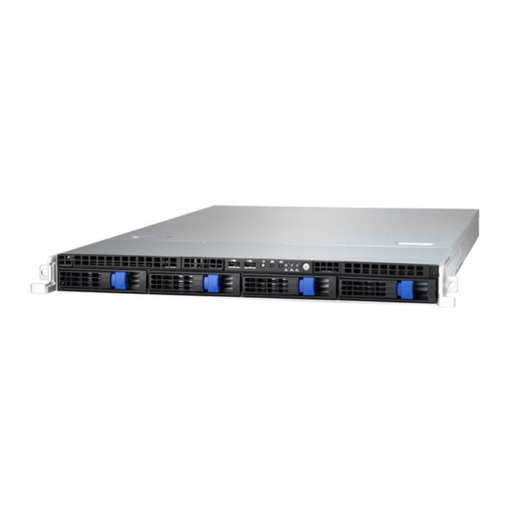
® TYAN also offers the GT24-B7066 in a version that can support up to four 2.5” or 3.5” hot-swap hard drives. The GT24-B7066 uses TYAN’s latest chassis featuring a robust structure and a solid mechanical enclosure. All of this provides GT24-B7066 the power and flexibility to meet the needs of nowadays server application. -
Page 16: Features
Features TYAN GT24B7066 (B7066G24W4H) Form Factor 1U Rackmount Gross Weight 17 kg Chassis Model GT24 System Dimension (D x W x 25.4" x 17.2" x 1.72" (645 x 436 x 43.6mm) Motherboard S7066WGM3NR Buttons (1) RST / (1) NMI / (1) ID / (1) PWR w/ LED... - Page 17 Non-operating Temp. - 40° C ~ 70° C (-40° F ~ 158° F) Environment In/Non-operating 90%, non-condensing at 35° C Humidity RoHS RoHS 6/6 Compliant Yes Barebone (1) GT24B7066 Barebone Package Manual (1) Quick Installation Guide Contains Installation CD (1) TYAN installation CD http://www.tyan.com...
- Page 18 TYAN GT24B7066 (B7066G24V4H) Form Factor 1U Rackmount Gross Weight 17 kg Chassis Model GT24 System Dimension (D x W x 25.4" x 17.2" x 1.72" (645 x 436 x 43.6mm) Motherboard S7066GM3NR Buttons (1) RST / (1) NMI / (1) ID / (1) PWR w/ LED...
- Page 19 Non-operating Temp. - 40° C ~ 70° C (-40° F ~ 158° F) Environment In/Non-operating 90%, non-condensing at 35° C Humidity RoHS RoHS 6/6 Compliant Yes Barebone (1) GT24B7066 Barebone Package Manual (1) Quick Installation Guide Contains Installation CD (1) TYAN installation CD http://www.tyan.com...
- Page 20 TYAN GT24B7066 (B7066G24W4HR【BTO】) Form Factor 1U Rackmount Gross Weight 17 kg Chassis Model GT24 System Dimension (D x W x 25.4" x 17.2" x 1.72" (645 x 436 x 43.6mm) Motherboard S7066WGM3NR Buttons (1) RST / (1) NMI / (1) ID / (1) PWR w/ LED...
- Page 21 Non-operating Temp. - 40° C ~ 70° C (-40° F ~ 158° F) Environment In/Non-operating 90%, non-condensing at 35° C Humidity RoHS RoHS 6/6 Compliant Yes Barebone (1) GT24B7066 Barebone Package Manual (1) Quick Installation Guide Contains Installation CD (1) TYAN installation CD http://www.tyan.com...
-
Page 22: Standard Parts List
Standard Parts List This section describes GT24-B7066 package contents and accessories. Open the box carefully and ensure that all components are present and undamaged. The product should arrive packaged as illustrated below. 1.4.1 Box Contents Component Description (1) 1U Barebone, (4) hot swap HDD bays ®... - Page 23 (1) M7016-PDB Power Distribution Board (B7066G24W4HR only) http://www.tyan.com...
-
Page 24: Accessories
® TYAN ’s website for service: http://www.tyan.com ® The web site also provides information of other TYAN products, as well as FAQs, compatibility lists, BIOS settings, etc. Sliding Rail x 1 and CPU Heatsink x 2 Screw Pack x 1... -
Page 25: About The Product
System Front View LED Control Panel Hot-swap HDD Bays M1008 FPB (Front Panel LED Control Board) USB Ports ID Button NMI Button Reset Button ID LED HDD LED Warning LED LAN1 LED LAN2 LED LAN3 LED Power on/off Button with LED http://www.tyan.com... -
Page 26: System Rear View
1.5.2 System Rear View 10 11 Power Supply Thumb Screw for Top Cover LAN3 (shared with IPMI) VGA Port Expansion Slot Expansion Slot USB Ports Serial Port ID LED Button LAN1 LAN2 http://www.tyan.com... -
Page 27: Led Definitions
ID LED will light blue if the system is identified. Users from remote sites can also activate the ID LED by entering a few commands in IPMI. For detailed software support, please visit http://www.tyan.com for the latest AST2300 user guide. - Page 28 100 Mbps Active Green Blinking Green Solid On Link 1000 Mbps Green Solid On Yellow Solid On (1Gbps) Active Green Blinking Yellow Solid On Link Yellow Solid On Yellow Solid On 10 Gbps Active Yellow Blinking Yellow Solid On http://www.tyan.com...
-
Page 29: Motherboard (S7066) Layout
The board you have received may not look exactly like the above diagram. The DIMM slot numbers shown above can be used as a reference when reviewing the DIMM population guidelines shown later in the manual. For the latest board revision, please visit our web site at http://www.tyan.com. http://www.tyan.com... -
Page 30: Jumpers & Connectors
LSI 2308 Enable/Disable jumper 2PHD_1 LSI IMR KEY (Optional) ID_LED ID LED SATA0/SATA1 Serial ATA Connector J19/J20/J64/J65/J66 Fan Connector (SYS_FAN1/2/3/4/5) J45/J63 CPU1/CPU0 Fan Power Connector Jumper Legend OPEN - Jumper OFF Without jumper cover CLOSED - Jumper ON With jumper cover http://www.tyan.com... -
Page 31: System Block Diagram (S7066)
1.5.6 System Block Diagram (S7066) http://www.tyan.com... -
Page 32: System Top View
(4) HDD trays (1) M1235 HDD Backplane Board (pre-installed) (1) M1008-FPB Front Panel Board (pre-installed) (6) 12038 hot-swap system fans (pre-installed) (1) M2091 Riser Card (pre-installed) (1) M2091-R Riser Card (pre-installed) (2) Expansion slots System Main Board Power Supply Module http://www.tyan.com... -
Page 33: Chapter 2: Setting Up
Caution! To avoid damaging the motherboard and the associated components, do not use torque force greater than 7kgf/cm (6.09 lb/in) on each mounting screw for motherboard installation. Do not apply power to the board if it has been damaged. http://www.tyan.com... -
Page 34: Precautions
Working on a system that is connected to a power supply can be extremely dangerous. Follow the guidelines below to avoid damage to GT24-B7066 or injury to yourself. Ground yourself properly before removing the top cover of the system. -
Page 35: Removing And Installing The Chassis Cover
Removing and Installing the Chassis Cover Follow these instructions to remove the GT24-B7066 chassis cover. Unless you are installing a hot-swappable component, be sure to turn off the system, disconnect all attached peripherals and disconnect the system from the electrical source. -
Page 36: Installing Motherboard Components
2. Push down the lever (1) and slightly pull away from the socket (2) to release the latch, and then lift up the lever to a fully open position (3). Do the same procedures to release the other lever. http://www.tyan.com... - Page 37 3. Lift the CPU socket cover to a fully open position. 4. Remove the protection cap from the CPU socket. 5. Place the CPU into the socket making sure that the gold arrow is located in the right direction. http://www.tyan.com...
- Page 38 7. Pull down the lever (1), press down (2) and hook towards the latch (3). Repeat the same procedures to hook the other lever. 8. Position the heatsink on top of the CPU and secure it with 4 screws. 9. Repeat steps 2 to 8 to install the second CPU and heatsink. http://www.tyan.com...
-
Page 39: Installing The Expansion Cards
2.3.2 Installing the Expansion Cards GT24-B7066 comes with a PCI-E riser bracket with two pre-installed PCI-E x16 riser cards. The two PCI-E riser cards connect to the two PCI-E slots on the mainboard. (2) PCI-E x16 slot direction (x16 link) Follow these instructions to install expansion cards. - Page 40 Unscrew the PCI dummy bracket. Slide to remove the PCI dummy bracket. Insert the expansion card to the riser bracket. Make sure the expansion card is connected to the PCI-E slot on the riser card and properly latched onto the riser bracket. http://www.tyan.com...
- Page 41 Attach the screw to secure the expansion card to the riser bracket. Insert the riser cards to the PCI-E slots on the main board as you align the riser bracket onto the chassis. Attach the 2 screws to secure the riser bracket to the chassis. http://www.tyan.com...
-
Page 42: Installing The Memory
Align and insert the memory module down onto the slot. When inserted properly, the memory slot locking levers lock automatically on the indentations at the ends of the module. Follow the recommended memory population table to install the other memory modules. http://www.tyan.com... - Page 43 Memory Population Option Table The following pictures show common types of DDR3 memory modules. http://www.tyan.com...
- Page 44 4. Dual-rank DIMMs are recommended over single-rank DIMMs. 5. Un-buffered DIMM can offer slightly better performance than registerd DIMM if populating only a single DIMM per channel. 6. Always install with CPU0 Socket and DIMM_0 Slot first, following the alphabetical order. http://www.tyan.com...
- Page 45 √ √ √ √ √ √ √ √ √ CPU1_DIMM_B1 √ √ √ √ √ √ √ √ √ CPU1_DIMM_C0 √ √ √ √ √ √ √ CPU1_DIMM_C1 √ √ √ √ √ CPU1_DIMM_D0 √ √ √ CPU1_DIMM_D1 √ http://www.tyan.com...
-
Page 46: Installing Hard Drives
2.3.4 Installing Hard Drives The GT24-B7066 can support up to four (4) 3.5” / 2.5” hard drives. Installing 3.5” Hard Drives Follow these instructions to install a 3.5” HDD. Warning!!! Always install the hard disk drive to the chassis after the chassis has been secured on the rack. - Page 47 Unscrew the 5 screws securing the HDD bracket to the HDD tray. Place the 3.5” hard disk drive into the HDD tray and secure the HDD to the HDD tray using 4 screws. Reinsert the HDD tray into the chassis. http://www.tyan.com...
- Page 48 Push to secure the locking lever until it clicks into place. http://www.tyan.com...
- Page 49 Follow these instructions to install a 2.5” HDD. Warning!!! Always install the hard disk drive to the chassis after the chassis has been secured on the rack. Press the locking lever latch and pull the locking lever open. Slide the HDD tray out. http://www.tyan.com...
- Page 50 Turn the HDD tray over and place the 2.5” HDD on its bay. Secure the HDD to the tray using 4 screws. Reinsert the HDD tray into the chassis. Push to secure the locking lever until it clicks into place. http://www.tyan.com...
-
Page 51: Rack Mounting
Mounting Ears Screw Pack x 1 2.4.1 Installing the Server in a Rack Follow these instructions to mount the TYAN GT24-B7066 into an industry standard 19” rack. NOTE: Before mounting the TYAN GT24-B7066 in a rack, ensure that all internal components have been installed and that the unit has been fully tested. - Page 52 Installing the Inner Rails to the Unit Screw the mounting ears to each side of the GT24-B7066 as shown using four screws from the supplied mounting ears screw pack. Draw out the inner rail from the rail assembly. When the rail comes to a stop, pull the tab to release the latch and completely draw the inner rail out.
- Page 53 (2) to secure the three hooks. Secure the inner sliding rail to the server using one M4 x 4L screw (C). Repeat steps 2 to 4 to secure the sliding rail to the other side of the server. http://www.tyan.com...
- Page 54 Secure the outer rails to the rack using four M5 screws and four washers (B) on each side. Rack Mounting the Server Pull out the middle rail to the latch position. Lift the unit and then insert the inner slide rails into the middle rails. http://www.tyan.com...
- Page 55 When the inner rails come to a stop, pull the tab to release the latch and push the whole system in. Secure the mounting ears of the unit to the rack using two M5 x 20L screws (A). http://www.tyan.com...
- Page 56 NOTE http://www.tyan.com...
-
Page 57: Chapter 3: Replacing Pre-Installed Components
This chapter explains how to replace the pre-installed components, including the S7066 Motherboard, M1008-FPB Front Panel Board, M1235-HDD BP HDD Backplane Board, PCI-E Riser Card, System Fan and Power Supply Unit etc. Disassembly Flowchart The following flowchart outlines the disassembly procedures. http://www.tyan.com... -
Page 58: Replacing The System Fan
Follow these instructions to remove the system fan. Remove the chassis cover (see 2.2 Removing and Installing the Chassis Cover on page 35). Disconnect all fan cables from the HDD backplane board. Lift the system fans from the chassis. http://www.tyan.com... - Page 59 Press the tab towards the direction of the arrow (1) and pull the fan (2) to detach it from the group. While holding the fan with two hands, push the fan downwards with both thumbs to release it from the fan cage. http://www.tyan.com...
-
Page 60: Installing The System Fan
Install the fan into the fan cage and connect the fan cage to the group. Align the system fans into the chassis. Connect the fan cables to the HDD backplane board. Install the chassis cover (see 2.2 Removing and Installing the Chassis Cover on page 35). http://www.tyan.com... -
Page 61: Replacing The Front Panel Board
Turn off the system, disconnect all attached peripherals and disconnect the system from the electrical source. Remove the two screws securing the front panel board to the chassis. Carefully pull out the front panel board. Disconnect the cables from the connectors on the front panel board. http://www.tyan.com... - Page 62 Remove the three screws securing the front panel board to the bracket. Slightly pull the front panel board away from the front panel connectors slot and then lift it to remove from the bracket. http://www.tyan.com...
-
Page 63: Installing The Front Control Board
Installing the Front Control Board Replace with a new front panel board and secure it to the bracket with three screws. Connect the cable connectors to the front panel board connectors. Insert the front panel board inside the chassis. http://www.tyan.com... - Page 64 Secure the front panel board to the chassis using two screws. http://www.tyan.com...
-
Page 65: Front Panel Board Features
Bottom: LAN1 LED (green) USB 1 Top: HDD LED (green) USB 2 Bottom: LAN2 LED (green) ID Switch (SW1) Top: Warning LED (amber) NMI Switch (SW2) Bottom: LAN3 LED (green) Reset Switch (SW3) Power Button (J6) Form Factor: TBD http://www.tyan.com... -
Page 66: Pin Definitions
J1: 2x5-pin USB Header Definition Definition USB1- USB2- USB1+ USB2+ J3: 2x15-pin SSI Front Panel Header Definition Definition PWD_LED+ ID_LED+ PW_LED- ID_LED- HDD LED+ SYS_FAULT1- HDD LED- SYS_FAULT2- PWR_SW- LAN1_LED+ LAN1_LED- RESET- ICH_SMBDAT ICH_SMBCLK ID_SW- INTRU# TEMP_SENSOR LAN2_LED+ NMI_SW LAN2_LED- LAN3_LED+ LAN3_LED- http://www.tyan.com... -
Page 67: Replacing The Hdd Backplane Board
Cover on page 35). Disconnect all the system fan cables attached to the HDD backplane board. Disconnect the power cables, SAS cable, and fan header cable. Remove the three screws securing the HDD backplane board bracket to the chassis. http://www.tyan.com... - Page 68 Lift the HDD backplane bracket to remove it from the chassis. Remove the ten (10) screws securing the HDD backplane board to the HDD backplane board bracket. Lift the HDD backplane board to remove it from the HDD backplane board bracket. http://www.tyan.com...
-
Page 69: Installing The Hdd Backplane Board
Connect the power cables, SAS cable, and fan header cable to the connectors on the HDD backplane board. Connect all the system fan cables to the connectors on the HDD backplane board. Install the chassis cover (see 2.2 Removing and Installing the Chassis Cover on page 35). http://www.tyan.com... -
Page 70: Hdd Bp Board Features
2x2P Power Connector (PW2) Fan Connector (FAN1) 4-P Power Connector (PW1) Fan Connector (FAN2) (J43) Fan Connector (FAN3) (J42) (J40) SGPIO For IOH (J41) Fan Connector (FAN4) Mini SAS Connector (J39) Form Factor 422.4 (L) mm x 38.7 (H) mm, 6-layer PCB http://www.tyan.com... -
Page 71: Connector Pin Definitions
Definition CPLD_JTAG_TCK CPLD_JTAG_TDO 3.3V CPLD_JTAG_TMS KEY Pin CPLD_JTAG_TDI J41: SGPIO For IOH Definition Definition SM_CLK SGPIO_0 SM_DATA SGPIO_1 SGPIO_2 KEY Pin SGPIO_3 HD_ERR_LED PW1: Big 4-pin Power Connector Definition Definition +12V PW2: 2X2-pin Power Connector Definition Definition +12V +12V http://www.tyan.com... -
Page 72: Replacing The Power Supply Unit
Remove the chassis cover (see 2.2 Removing and Installing the Chassis on page 35). Cover Disconnect the power cables from the HDD backplane board. Disconnect the power cable from the mainboard connector. Disconnect the power cables from the mainboard connectors. http://www.tyan.com... - Page 73 Remove the two screws securing the power supply to the chassis. Remove the five screws securing the power supply to the chassis. Slide the power supply out from the chassis. http://www.tyan.com...
- Page 74 Remove the two screws securing the power supply panel bracket to the power supply unit. Detach the power supply panel bracket from the power supply unit. Remove the two screws to detach the bracket from the power supply unit. http://www.tyan.com...
-
Page 75: Installing The Power Supply Unit
On the back of the new power supply unit, attach the bracket using two screws. Align and attach the power supply panel bracket to the front of the power supply unit using two screws. Slide the power supply unit into the chassis bay and secure it using five screws. http://www.tyan.com... - Page 76 Attach the two screws to secure the power supply unit to the chassis. Connect the power connectors to the motherboard. Connect the power connectors to the HDD backplane board. Install the chassis cover (see 2.2 Removing and Installing the Chassis Cover on page 35). http://www.tyan.com...
-
Page 77: Replacing The Motherboard
Remove the chassis cover (see 2.2 Removing and Installing the Chassis on page 35). Cover Unscrew the 2 screws securing the riser bracket to the chassis. Lift the riser bracket up. Disconnect all the cables connected to the motherboard. http://www.tyan.com... - Page 78 Set the necessary jumpers (see 1.5.5 Jumpers & Connectors on page 30 for jumper placement). Secure the motherboard to the chassis using nine screws (see marked image above). Connect the cable connectors (see 1.5.5 Jumpers & Connectors on page 30 for connector placement). http://www.tyan.com...
- Page 79 Insert the riser cards to the PCI-E slots on the motherboard as you align the riser bracket onto the chassis. Attach the two screws to secure the riser bracket to the chassis. Install the the chassis cover (see 2.2 Removing and Installing the Chassis Cover on page 35). http://www.tyan.com...
- Page 80 NOTE http://www.tyan.com...
-
Page 81: Appendix I: Cable Connection Tables
SGPIO Cable M1235 Connect to S7066WGM3NR → Mini-SAS Cable LS1_SAS_CON1 → Fan cable 3. Control Cable and USB Cable M1008-G2024 LED Control Board to S7066 MB M1008-G2024 Connect to S7066 → Control Cable J39 & J44 → USB Cable http://www.tyan.com... - Page 82 2x4P P2 PWR3 → 2x4P P7 PWR2 → PSMI P8 PSU to M1235 BP BD 500W PSU Connect to M1235 → 2x2P P3 → B4P P4 5. Chassis Intrusion Cable Chassis Intrusion Cable Chassis Connect to S7066 → Intrusion Cable http://www.tyan.com...
-
Page 83: Appendix Ii: Fan And Temp Sensors
Fan Sensor: It is located in the third pin of the fan connector, which detects the fan speed (rpm) Temp Sensor: PCH Area Temp, SAS Area Temp and M/B Inlet Temp. They detect the system temperature around. NOTE: The system temperature is measured in a scale defined by Intel, not in Fahrenheit or Celsius. http://www.tyan.com... - Page 84 BIOS Temp Sensor Name Explanation: http://www.tyan.com...
- Page 85 BIOS FAN Sensor Name Explanation CPU0_FAN Fan speed of CPU0_FAN CPU1_FAN Fan speed of CPU1_FAN SYS_FAN_1 Fan speed of SYS_FAN_1 SYS_FAN_2 Fan speed of SYS_FAN_2 SYS_FAN_3 Fan speed of SYS_FAN_3 SYS_FAN_4 Fan speed of SYS_FAN_4 SYS_FAN_5 Fan speed of SYS_FAN_5 http://www.tyan.com...
- Page 86 NOTE http://www.tyan.com...
-
Page 87: Appendix Iii: Fru Parts Table
Appendix III: FRU Parts Table GT24-B7066 FRU Parts Item Model Number Part Number Picture Description M2091 411739100498 PCI-E X16 1U Riser Card (Left) Riser Card PCI-E X16 1U Riser Card (Right) M2091-R 411790500004 Mini-SAS cable, 500m CCBL-0689 422797800004 CCBL-0317 332810000397... - Page 88 NOTE http://www.tyan.com...
-
Page 89: Appendix Iv: Technical Support
By offering plenty of options for users, MiTAC serves multiple market segments with the industry’s most competitive services to support them. Please feel free to contact us directly for this service at tech-support@tyan.com Help Resources: 1. See the beep codes section of this manual. - Page 90 (RMA) number. The RMA number should be prominently displayed on the outside of the shipping carton and the package should be mailed prepaid. TYAN will pay to have the board shipped back to you. TYAN® GT24-B7066 Service Engineer’s Manual V1.0 Document No.: D2230-100 http://www.tyan.com...
Need help?
Do you have a question about the GT24-B7066 and is the answer not in the manual?
Questions and answers