Table of Contents
Advertisement
SPECIFICATIONS
Wingspan:
Wingspan:
80 in [2030 mm]
80 in [2030 mm]
Length:
67 in [ 1700 mm]
2
Wing Area:
1184 in
[76.4 dm
WARRANTY
Great Planes
®
Model Manufacturing Co. guarantees this kit to
be free from defects in both material and workmanship at the
date of purchase. This warranty does not cover any component
parts damaged by use or modification. In no case shall Great
Planes' liability exceed the original cost of the purchased kit.
Further, Great Planes reserves the right to change or modify this
warranty without notice.
In that Great Planes has no control over the final assembly or
material used for final assembly, no liability shall be assumed nor
accepted for any damage resulting from the use by the user of
the final user-assembled product. By the act of using the
user-assembled product, the user accepts all resulting liability.
If the buyer is not prepared to accept the liability associated
with the use of this product, the buyer is advised to return
READ THROUGH THIS MANUAL BEFORE STARTING CONSTRUCTION. IT CONTAINS IMPORTANT
INSTRUCTIONS AND WARNINGS CONCERNING THE ASSEMBLY AND USE OF THIS MODEL.
© 2015 Great Planes Model Mfg. A subsidiary of Hobbico,
12.75– 13.75 lbs
12.75– 13.75 lbs
Weight:
Weight:
[5780 – 6230 g]
[5780 – 6230 g]
Wing
25– 27 oz/ft
2
]
Loading:
[76– 82 g /dm
®
Inc.
INSTRUCTION
MANUAL
Radio:
Radio:
4-6 Channel
4-6
Engine:
E
i
1.8− 2.0 cu in [30 − 35 cc]
1 8 2 0
2
2
Electric:
RimFire 1.60 (63-62-250) Brushless
]
this kit immediately in new and unused condition to the
place of purchase.
To make a warranty claim send the defective part or item to
Hobby Services at the address below:
Hobby Services
3002 N. Apollo Dr. Suite 1
Champaign IL 61822 USA
Include a letter stating your name, return shipping address, as
much contact information as possible (daytime telephone
number, fax number, e-mail address), a detailed description of
the problem and a photocopy of the purchase receipt. Upon
receipt of the package the problem will be evaluated as quickly
as possible.
Champaign, Illinois
(217) 398-8970, Ext 5
airsupport@greatplanes.com
MX 30cc
6
Chan
Ch
anne
nel
l
i [30 35
]
™
GPMA1210
Advertisement
Table of Contents

Related Manuals for GREAT PLANES ESCAPADE MX 30cc


Summary of Contents for GREAT PLANES ESCAPADE MX 30cc
- Page 1 3002 N. Apollo Dr. Suite 1 Champaign IL 61822 USA In that Great Planes has no control over the final assembly or material used for final assembly, no liability shall be assumed nor Include a letter stating your name, return shipping address, as...
-
Page 2: Table Of Contents
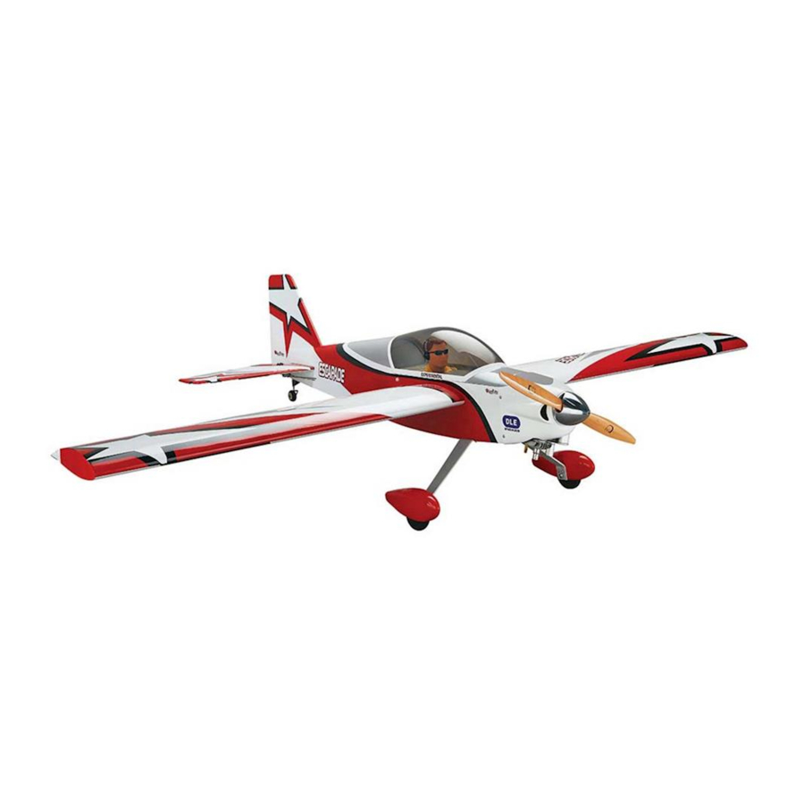
Continuing with the success of the Escapade line, Great Protect Your Model, Yourself & Others… Planes brings you the Escapade MX 30cc ARF. This is a Follow These Important Safety Precautions great fi rst gas powered model. The plane is as easy to fl y 1. -
Page 3: Decisions You Must Make
The Escapade MX 30cc ARF can be flown with a minimum of to reinforce the high stress points and/or substituting a 4-channel radio. -
Page 4: Additional Items Required
Here is a list of optional tools mentioned in the manual that Required Hardware and Accessories will help you build the Escapade MX 30cc ARF. ❍ 2 oz. [57g] spray CA activator (GPMR6035) ❍ (1) Dubro #554 X-Large Tygon Fuel Line (DUBQ0427) ❍... -
Page 5: Kit Contents
fi rms. Hardware items (screws, nuts, bolts) are also Order No. Description available from these outlets. GPMA5380 Wing Set To locate a hobby dealer, visit the Great Planes web site at GPMA5381 Fuselage Set www.greatplanes.com. Choose “Where to Buy”. Follow the GPMA5382 Tail Surface Set instructions provided on the page to locate a U.S., Canadian... -
Page 6: Preparations
PREPARATIONS ❏ 1. Firmly pull on each of the control surfaces to confi rm they are securely glued. ❏ 2. Tighten the covering with a covering iron as needed. ASSEMBLE THE WING Aileron Servo Installation Begin with the left wing panel. ❏... - Page 7 ❏ ❏ ❏ ❏ 6. Install servo horn. 10. Position control horn on aileron. ❏ ❏ 7. Aileron pushrod components. ❏ ❏ 8. Install the 4-40 threaded clevis. ❏ ❏ 11. Mount control horn. ❏ ❏ 9. Attach clevis to control horn.
- Page 8 HOW TO SOLDER Apply a few drops of soldering fl ux to the end of the pushrod. “Tin” the end of the pushrod by applying heat. Apply silver solder to the heated area. The pushrod should melt the solder, not the fl ame of the torch. The end of the pushrod should be tinned all the way around.
-
Page 9: Flap Servo Installation (Optional)
Flap Servo Installation (Optional) Flaps are not necessary to land the 30cc Escapade. However, if you have never fl own with fl aps, the 30cc Escapade is a great plane to learn with. ❏ 5. Install the fl ap servo following the same procedure used to install the aileron servos. -
Page 10: Assemble The Fuselage
ASSEMBLE THE FUSELAGE Install the Tail ❏ 5. Check the alignment of the horizontal stabilizer. The distance from the center of the nose of the fuselage to the tips of the horizontal stabilizer should be equal. ❏ 1. Slide the Carbon Wing Tube into the fuselage. The wing and stabilizer should be parallel. - Page 11 ❏ 6. Use 30-minute epoxy to glue the stabilizer in the fuselage. ❏ 8. Glue the fi ller blocks on both sides of the fuselage. ❏ 9. Attach the tail gear to the fuselage. ❏ 7. Use 30-minute epoxy to glue the vertical fi n in the fuselage.
-
Page 12: Install The Main Landing Gear
❏ ❏ 10. Install the tail wheel. 2. Cut the axle to length. Install the Main Landing Gear ❏ 3. File a fl at spot at the end of the axle. ❏ 1. Install the 3/16” [4.8mm] axles. -
Page 13: Install The Rudder And Elevator Servos
❏ ❏ 4. Install the main wheel. 6. Install the main landing gear on the fuselage. Install the Rudder and Elevator Servos ❏ 1. Install the rudder servo and plug it into the receiver. Temporarily plug the receiver battery into the receiver. ❏... - Page 14 ❏ 4. Install a 4-40 threaded coupler to the end of both pull- pull cables. ❏ 5. Install a 4-40 nut and threaded clevis on the coupler. ❏ 8. Attach rudder control horns. ❏ 6. Insert the pull-pull cables in the pushrod guide tubes. Attach the clevises to the servo arm.
- Page 15 ❏ 12. Install the elevator servos. Join the two servo leads with a Y-harness and plug the Y-harness into the receiver. ❏ 10. Pull the pull-pull cables tight and attach them to the rudder control horns. ❏ 13. Install the elevator control horns and attach the 4-40 ❏...
-
Page 16: Motor Installation
Electric Motor Installation Proceed to Engine and Tank Installation (page 19) if a gas engine will be installed. ❏ 14. Install the solder clevis. ❏ 1. Use epoxy to glue the front and back plates of the motor box together. ❏... - Page 17 ❏ ❏ 3. Glue three of the sides on. 6. Open the cooling hole. ❏ ❏ 4. Glue eight pieces of triangle stock between the front 7. Attach the motor box to the fi rewall. plate and the sides and the back plate and the sides. Then, glue the fourth side on.
-
Page 18: Engine Installation
❏ ❏ 9. Mount the ESC. Connect the wires from the ESC to the 14. Make two straps from the remaining hook and loop motor wires. material. Install the receiver, reciever switch and receiver battery. ❏ 15. Plug the ESC into the receiver. Check that the throttle is set to reverse on the Futaba transmitter. - Page 19 ❏ 6. Make three straps from the supplied hook and loop material. ❏ 3. Temporarily mount the engine using the hardware included with the engine. ❏ 7. Install the straps on the fuel tank tray. ❏ 4. Mark the fuel line, throttle and choke pushrod locations on the fi...
- Page 20 ❏ 11. Install the ignition battery and ignition module. ❏ 12. Reinstall the engine. ❏ 15. Install the throttle and choke servos and plug them into the receiver. ❏ 16. Make two straps from the remaining hook and loop material. Install the receiver switch, receiver and receiver battery. ❏...
- Page 21 ❏ ❏ 18. Install the choke pushrod. 22. Cut the outer pushrod tube. ❏ 23. Roughen the outer pushrod with sandpaper. ❏ 19. Assemble the choke clevis. ❏ 24. Install the outer pushrod. ❏ 20. Install the clevis on the choke servo. ❏...
-
Page 22: Assemble The Fuel Tank
❏ 3. Insert the brass tubes in the fuel tank stopper and stopper plates. ❏ 26. Install the throttle pushrod using the same procedure ❏ 4. Solder the barbs on the other end of the two shorter as used on choke pushrod. We recommend that a throttle brass tubes. -
Page 23: Install The Fuel Tank
Install the Fuel Tank ❏ 7. Loosely install the fuel tank stopper screw. ❏ 1. Install and mark the fuel lines: Vent, Carb and Fill. ❏ 2. Secure the fuel tank in the fuselage. ❏ 8. Slide the aluminum ring over the fuel tank neck. ❏... -
Page 24: Install The Cowl
Install the Cowl For the electric installation, skip to step 2. ❏ 2. Position the cowl. ❏ 1. Trim the cowl to fi t over the head and muffl er. ❏ 3. Drill 5/64" [1.5mm] pilot holes. Attach the cowl using #4x5/8"... -
Page 25: Get The Model Ready To Fly
GET THE MODEL READY TO FLY 4-CHANNEL RADIO SET UP (STANDARD MODE 2) Check the Control Directions RIGHT AILERON RUDDER MOVES UP MOVES LEFT AILERON RIGHT MOVES DOWN FULL ELEVATOR THROTTLE MOVES DOWN ❏ 3. Make certain that the control surfaces and the carburetor respond in the correct direction as shown in the diagram. -
Page 26: Install The Propeller
LESS Pushrod Farther Out THROW Pushrod Closer In MORE THROW Pushrod Farther Out Pushrod Closer In ❏ 4. Once the throws are set, apply a drop of threadlocker to the threads and tighten the 4-40 nuts against the clevises. Slide the silicone retainers over the clevises. IMPORTANT: Now that you have the throws set, be sure to set the failsafe on the radio. -
Page 27: Balance The Model Laterally
❏ 1. With the wing level, have an assistant help you lift the motor batteries installed, use a Great Planes C.G. Machine or model by the engine propeller shaft and the bottom of the apply narrow (1/16” [2mm]) strips of tape at the front and rear fuse under the TE of the fi... -
Page 28: Preflight
leather glove, such as a welder’s glove. When hand starting PREFLIGHT gas engines, if the engine should backfire, the large prop can cause severe injury to your hand and fingers. Identify Your Model ● Do not run the engine in an area of loose gravel or sand; the propeller may throw such material in your face or eyes. -
Page 29: Ama Safety Code (Excerpts)
FLYING a safe location, preferably outside. Place it in a bucket, The Escapade MX 30cc ARF is a great-fl ying sport model that covering the battery with sand. Never use water to try and put out a LiPo fi re. -
Page 30: Takeoff
It is a good idea to have an assistant on the fl ight line with you to keep an eye on other traffi c. Take it easy with the Escapade MX 30cc ARF for the fi rst few fl ights, gradually getting acquainted with it as you gain confi dence. Adjust the trims to maintain straight and level fl... - Page 31 Fill in your battery type, voltage and capacity. Then tape this chart to bottom of canopy hatch for reference: LOW RATE HIGH RATE ELEVATOR 7/8" [22mm] 13° 5/8" [16mm] 9° Up/Down RUDDER 2" [51mm] 19° 1-3/4" [44mm] 17° Left/Right AILERON 3/4"...
Need help?
Do you have a question about the ESCAPADE MX 30cc and is the answer not in the manual?
Questions and answers