Table of Contents
Advertisement
Quick Links
Advertisement
Table of Contents

Related Manuals for Contura C i41


Summary of Contents for Contura C i41
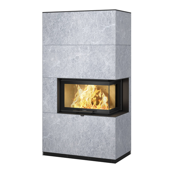
- Page 1 Installation Instruction C i41 www.contura.eu...
-
Page 2: Declaration Of Performance
See rating plate on the insert Intended area of use Heating of rooms in residential buildings Fuel Wood MANUFACTURER Name NIBE AB / Contura Address Box 134, Skulptörvägen 10 SE-285 23 Markaryd, Sweden CHECKS According to AVCP System 3 European standard... -
Page 3: Table Of Contents
A warm welcome to the Contura family. We hope you will get a great deal of pleasure from your new stove. As a new owner of a Contura stove, you have secured a product with timeless design and long service life. -
Page 4: Technical Specifications
Wall behind This manual contains instructions about Before installing a stove or erecting a If your Contura i41 is to be installed how Contura i41 must be assembled chimney, it is necessary for you to make against a combustible wall, the wall must and installed. -
Page 5: Surround
SURROUND Surround Only handle the stone with clean hands or gloves. Handle the stone that all the stone sections are straight and that all stones are of a carefully so as not to damage fragile corners and edges. uniform height. Use shims if necessary. The stone is a natural material, which means that there may be certain irregularities and variations in its appearance. -
Page 6: Chimney
CHIMNEY Chimney The stove is type approved in accordance with EN 13240 and Carefully check that the chimney is sealed and that there is no must be connected to a chimney dimensioned for at least 350°C leakage around soot hatches and flue connections. the external connection diameter is Ø150 mm. -
Page 7: Supply Of Combustion Air
SUPPLY Supply of combustion air Supply of combustion must be provided. Combustion air can be provided directly via a duct from outside, or indirectly via a vent in the outer wall of the room where the stove is placed. The amount of combustion air that is used for combustion is approx. -
Page 8: Installation Distances
INSTALLATION DISTANCES Installation distances C i41 Without shelf/ Bench Important! The dimension diagrams only show the minimum permitted the flue. The minimum distance to combustible parts of the installation distances for the stove. When connecting to a building or interior decoration in front of the stove must steel flue, also note the safety distance requirements of be at least 1.5 m. - Page 9 INSTALLATION DISTANCES Installation distances C i41 With shelf/ Bench Combustible roof Brännbart tak Ext. Ø 150 Utv. Ø 150 1010 Combustible roof Brännbart tak Ext. Ø 150 Utv. Ø 150 1560...
-
Page 10: Corner Installation
CORNER INSTALLATION Corner installation Contura i41 can be positioned in a corner with non-combustible walls according to the section “Walls behind” on page 228. This type of installation includes the following: - Lower rear brace is withdrawn (image 1) - Supplementary support for the top is installed (image 1) -
Page 11: Positioning The Insert
INSERT PLACEMENT Positioning the insert If the protective screen is selected – read these The stove can be positioned tight to the instructions before installing the insert or chimney. wall behind. When installing against non-vertical Position the floor section and check that the minimum permitted walls and to facilitate installation it is distance to combustible material is kept. - Page 12 INSERT PLACEMENT Place a spirit level on the moulding below the door, and adjust the front feet to the specified measurement from the floor to the moulding's lower edge and until the spirit level is straight. 13 mm Position the spirit level as illustrated and adjust the rear feet until the stove is level.
-
Page 13: Assembling The Stand
STAND ASSEMBLY Assembling the stand 90° 90° 5 0 m ~ 4 8 This brace (ring 1) The lower brace (ring 2) must must be twisted with protrude on the outside and the cut-out upwards to forwards, and provide surfaces for create clearance for the the stones. - Page 14 STAND ASSEMBLY x 12 M5 x 9 M4 x 10 M5 x 9 90°...
- Page 15 STAND ASSEMBLY M5 x 9 M5 x 9 M4 x 10...
- Page 16 STAND ASSEMBLY M5 x 9 M5 x 18...
- Page 17 STAND ASSEMBLY Align the stand using a spirit level. 13 mm 3 0 m M i n Ensure that the disc base can be pushed around the stand. Adjust the base height with the rubber feet. On heavily sloping floors the insert and stand may need to be raised further.
-
Page 18: Assembling The Surround Without Shelf/Bench
ASSEMBLING THE SURROUND WITHOUT SHELF/BENCH Assembling the surround – without shelf/bench 2 mm Place a foam sheet on the floor to prevent the stone corners from becoming damaged when handling. - Page 19 ASSEMBLING THE SURROUND WITHOUT SHELF/BENCH The stone must lie flush against the stand. This panel can be removed for servicing. Lock it in place by inserting two screws through the moving catch (A) in the front panel. Do not tighten the screws – it must be possible to be move the catch upwards to detach the panel.
- Page 20 ASSEMBLING THE SURROUND WITHOUT SHELF/BENCH When the front panel is correctly positioned in the depth direction, it must be lowered again for the installation of the side panels. Beware of the corners!
- Page 21 ASSEMBLING THE SURROUND WITHOUT SHELF/BENCH Check that the top of the stones are level using a spirit level. Use supplied shims if necessary. Carry out on the remaining stone sections. Place a foam sheet on the floor to prevent the stone corners from becoming damaged when handling.
- Page 22 ASSEMBLING THE SURROUND WITHOUT SHELF/BENCH 10 mm M5 x 9...
- Page 23 ASSEMBLING THE SURROUND WITHOUT SHELF/BENCH M6 x 10 Allen screw 4 The front panel must rest on the stand's metal tab, not on the lower front In the event of having to insert shims, do this on the metal tab.
- Page 24 ASSEMBLING THE SURROUND WITHOUT SHELF/BENCH M6 x 20 Allen screw 4...
- Page 25 ASSEMBLING THE SURROUND WITHOUT SHELF/BENCH Adjust the stones with the screws as necessary. 4 mm Final installation: See page 273...
-
Page 26: Assembling The Surround With Shelf
ASSEMBLING THE SURROUND WITH SHELF Assembling the surround – with shelf Place a foam sheet on the floor to prevent the stone corners from becoming damaged when handling. - Page 27 ASSEMBLING THE SURROUND WITH SHELF The stone must lie flush against the stand. M6 x 20 Allen screw 4 This panel can be removed for servicing. Lock it in place by inserting two screws through the moving catch (A) in the front panel.
- Page 28 ASSEMBLING THE SURROUND WITH SHELF When the front panel is correctly positioned in the depth direction, it must be lowered again for the installation of the side panels. Beware of the corners! Check that the top of the stones are level using a spirit level.
- Page 29 ASSEMBLING THE SURROUND WITH SHELF 2 mm M10 x 20 Allen 16 mm Do not tighten the screws completely in order to allow some lateral adjustment of the shelf after installation.
- Page 30 ASSEMBLING THE SURROUND WITH SHELF M5 x 9...
- Page 31 ASSEMBLING THE SURROUND WITH SHELF Ensure that there is a gap of about 2 mm between the shelf and insert and that the damper can move freely. 90°...
- Page 32 ASSEMBLING THE SURROUND WITH SHELF 10 mm M5 x 9...
- Page 33 ASSEMBLING THE SURROUND WITH SHELF M6 x 10 Allen screw 4 The front panel must rest on the stand's metal tab, not on the lower front In the event of having to insert shims, do this on the metal tab.
- Page 34 ASSEMBLING THE SURROUND WITH SHELF M6 x 20 Allen screw 4...
- Page 35 ASSEMBLING THE SURROUND WITH SHELF Adjust the stones with the screws as necessary. Final installation: See page 273...
-
Page 36: Assembling The Surround With Bench
ASSEMBLING THE SURROUND WITH BENCH Assembling the surround – with bench Place a foam sheet on the floor to prevent the stone corners from becoming damaged when handling. - Page 37 ASSEMBLING THE SURROUND WITH BENCH The stone must lie flush against the stand. M6 x 20 Allen screw 4 This panel can be removed for servicing. Lock it in place by inserting two screws through the moving catch (A) in the front panel.
- Page 38 ASSEMBLING THE SURROUND WITH BENCH When the front panel is correctly positioned in the depth direction, it must be lowered again for the installation of the side panels. Beware of the corners! Check that the top of the stones are level using a spirit level.
- Page 39 ASSEMBLING THE SURROUND WITH BENCH 2 mm...
- Page 40 ASSEMBLING THE SURROUND WITH BENCH M6 x 16 Allen 10...
- Page 41 ASSEMBLING THE SURROUND WITH BENCH M6 x 16 Allen screw 4...
- Page 42 ASSEMBLING THE SURROUND WITH BENCH M6 x 12 Allen screw 4 Adjust the feet on the leg so that the bench top has a flat mating surface. Position the bench top and check that it is stable and does not rock.
- Page 43 ASSEMBLING THE SURROUND WITH BENCH Ensure that there is a gap of about 2 mm between the shelf and insert and that the damper can move freely. 90° 10 mm...
- Page 44 ASSEMBLING THE SURROUND WITH BENCH M5 x 9...
- Page 45 ASSEMBLING THE SURROUND WITH BENCH M6 x 10 Allen screw 4 The front panel must rest on the stand's metal tab, not on the lower front In the event of having to insert shims, do this on the metal tab.
- Page 46 ASSEMBLING THE SURROUND WITH BENCH M6 x 20 Allen screw 4...
- Page 47 ASSEMBLING THE SURROUND WITH BENCH Adjust the stones with the screws as necessary. 4 mm...
- Page 48 ASSEMBLING THE SURROUND WITH BENCH Final installation: See page 273...
-
Page 49: Assembling Grate And Top
INSTALLING GRATE AND TOP Assembling grate and top For rear connection M6 x 10 Allen screw 4... - Page 50 INSTALLING GRATE AND TOP...
- Page 51 INSTALLING GRATE AND TOP For top connection M6 x 10 Allen screw 4...
- Page 52 INSTALLING GRATE AND TOP...
- Page 53 INSTALLING GRATE AND TOP Disc base...
- Page 54 INSTALLING GRATE AND TOP Adjust the rubber feet on the disc base so that the gap up to the stone is 5 mm. Final inspection of the installation It is extremely important that the installation is inspected by an authorised inspection body before the stove is used.
- Page 56 NIBE AB · Box 134 · SE-285 23 ? Markaryd · Sweden www.contura.eu Contura reserves the right to change dimensions and procedures described in these instructions at any 811206 IAV SE-EX Ci41-11 time without special notice. The current edition can be 2015-03-24 downloaded from www.contura.eu...
Need help?
Do you have a question about the C i41 and is the answer not in the manual?
Questions and answers