Advertisement
Quick Links
Advertisement

Related Manuals for Contura i50


Summary of Contents for Contura i50
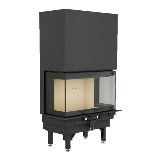
- Page 1 Installation instruction Ci50 www.contura.eu...
- Page 2 See rating plate on the insert Intended area of use Heating of rooms in residential buildings Fuel Wood MANUFACTURER Name NIBE AB / Contura Address Box 134, Skulptörvägen 10 SE-285 23 Markaryd, Sweden CHECKS According to AVCP System 3 European standard...
- Page 3 A warm welcome to the Contura family. We hope you will get a great deal of pleasure from your new insert. As a new owner of a Contura insert, you have secured a product with timeless design and long service life.
- Page 4 If the floor under the stove is flammable, how to assemble and install the Contura it must be protected by a non-flammable Model i50. To ensure the function and safety of material e.g. natural stone, concrete or Output 6-11 kW the insert, we recommend that installation at least 0.7 mm thick metal.
- Page 5 IMPORTANT DIMENSIONS / PRIOR TO INSTALLATION Important dimensions C i50 Tilluftsstos Ø100 Air Inlet Ø100 Prior to installation Opening sidelights...
- Page 6 PRIOR TO INSTALLATION Remove the loose parts from the firebox. The insert is secured to the pallet by the two rails, remove the screws and remove the angle brackets. Reinstall the screws on the legs before moving the insert from the pallet. 3 mm 10 mm...
- Page 7 PRIOR TO INSTALLATION Check wire routing and remove the transport locking devices! 10 mm...
- Page 8 For installation in the UK and in smoke control areas Mandatory for smoke control areas The Contura i50 and i51, 8 kW woodburning stoves has been recommended as suitable for use in smoke control areas. This when burning wood logs and operated in accordance with these instructions and when fitted with a permanent stop to prevent closure of primary air control beyond the 52 mm²...
- Page 9 PRIOR TO INSTALLATION Installing heat defl ector 10 mm...
- Page 10 PRIOR TO INSTALLATION Installing the fi rebox cladding...
- Page 11 PRIOR TO INSTALLATION...
- Page 12 PRIOR TO INSTALLATION...
- Page 13 OPTION Installing Powerstone Option Install the Powerstone blocks as illustrated. • With combustion air hose as option – now install according to separate instructions. • With recessing frame as option – now install according to separate instructions.
- Page 14 INSTALLATION Installation Ensure that the installation meets national and regional regulations. The installation must be approved by an authorized inspection body. Supply of combustion air must be provided. Combustion air can be provided directly via a duct from outside, or indirectly via a vent in the outer wall of the room where the stove is placed.
- Page 15 CHIMNEY / SELF-CLOSING DOOR Chimney The insert is approved and must be connected to a chimney Note that a flue with sharp bends and horizontal routing reduces dimensioned for at least 350°C, the external connection diameter the draught in the chimney. The maximum horizontal flue is 1 m, is Ø150 mm.
- Page 16 SELF-CLOSING DOOR...
- Page 17 RECESSING THE INSERT Recessing the insert When recessing the insert, adjacent walls that are not classed When connecting a steel flue, please refer to the particular as fire walls or are considered unsuitable for heat loads must manufacturer's installation instructions. Observe the safety be protected by non-combustible material according to the distance to combustible material required by the steel flue Heat specification below.
- Page 18 RECESSING THE INSERT Recess example Wall of combustible material Wall of non-combustible material that is not in contact with combustible The dimensions are the material and therefore has no minimum minimum dimensions, thickness requirement. unless otherwise stated. Chimney breast Wall of non-combustible material, made of 100 mm aerated concrete in the recess example.
- Page 19 RECESSING THE INSERT Sealing Avtätning Area out 600 cm Area ut 600 cm Area out 600 cm Area ut 600 cm Area in 600 cm Area in 600 cm Area in 600 cm Area in 600 cm Area out 600 cm Area ut 600 cm Area out 600 cm Area ut 600 cm...
- Page 20 NIBE AB · Box 134 · 285 23 · Markaryd · Sweden www.contura.eu Contura reserves the right to change dimensions and procedures described in these instructions at any 811267 IAV SE-EX Ci50-6 time without special notice. The current edition can be 2017-05-17 downloaded from www.contura.eu...
Need help?
Do you have a question about the i50 and is the answer not in the manual?
Questions and answers