
Related Manuals for Keithley 2290-10


Summary of Contents for Keithley 2290-10
- Page 1 Model 2290-10 10 kV Power Supply User’s Manual 2290-10-900-01 Rev. A / December 2013 *P22901090001A* 2290-10-900-01 A Greater M esure of Confidence A T ektr onix Company...
- Page 2 All rights reserved. Any unauthorized reproduction, photocopy, or use of the information herein, in whole or in part, without the prior written approval of Keithley Instruments, Inc. is strictly prohibited. All Keithley Instruments product names are trademarks or registered trademarks of Keithley Instruments, Inc.
-
Page 3: Safety Precautions
Keithley Instruments products are designed for use with electrical signals that are measurement, control, and data I/O connections, with low transient overvoltages, and must not be directly connected to mains voltage or to voltage sources with high transient overvoltages. - Page 4 (note that selected parts should be purchased only through Keithley Instruments to maintain accuracy and functionality of the product). If you are unsure about the applicability of a replacement component, call a Keithley Instruments office for information.
-
Page 5: Table Of Contents
Line voltage selection ........................ 2-2 Interlock circuit ........................2-2 Connecting the interlock of the Model 2290-10 ................. 2-3 Connecting the Model 2290-10 output to a custom text fixture ..........2-4 Basic operations ....................... 3-1 Numeric and cursor keys ..................... 3-1 Select, Enter, Clear ...................... - Page 6 Table of Contents Model 2290-10 10 kV Power Supply User's Manual Set the GPIB address ....................... 4-3 Bus connections ........................4-3 Command syntax ......................... 4-3 Multiple commands ........................4-3 Command buffer ........................4-3 Command queries ........................4-3 Command examples ......................... 4-4 Remote commands ......................
- Page 7 Model 2290-10 10 kV Power Supply User's Manual Table of Contents No high voltage ........................9-2 Service ..........................9-2...
-
Page 8: Introduction
Rear-panel familiarization............1-6 Welcome Thank you for choosing a Keithley Instruments product. The Model 2290-10 10 kV power supply is designed for use in the research laboratory and for test applications. It also has excellent regulation and low output voltage ripple. The digital displays provide accurate readings of voltage and current and also provide for easy, precise setting of output values using digital entry of current and voltage values. -
Page 9: Organization Of Manual
Unpacking and inspecting Inspect for damage Upon receiving the Model 2290-10, carefully unpack the unit, and inspect for any obvious signs of physical damage that might have occurred during shipment. Notify the shipping agent of any damage immediately. -
Page 10: Shipment Contents
Model 2290-10-SHVUC – 10 kV SHV male to unterminated cable; 3.05 meters (10 feet) • Model 2290-10-SHV – 10 kV SHV male to SHV male cable; 3.05 meters (10 feet) • Model 2290-INT-CABLE – 3-pin interlock connector to unterminated cable; 3.05 meters (10 feet) •... -
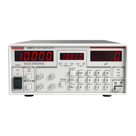
Page 11: Front-Panel Familiarization
Section 1: Introduction Model 2290-10 10 kV Power Supply User's Manual Front-panel familiarization The Model 2290-10 front panel is shown below. Descriptions of the controls on the front panel follow the figure. Figure 1: Model 2290-10 Front panel 2290-10-900-01 Rev. A/December 2013... - Page 12 Model 2290-10 10 kV Power Supply User's Manual Section 1: Introduction POWER button Applies power to the instrument. The instrument always powers up with the high voltage off. The current instrument configuration and any saved instrument presets are stored in non-volatile memory. The serial number, firmware version, and model number are displayed when power is turned on.
-
Page 13: Rear-Panel Familiarization
Section 1: Introduction Model 2290-10 10 kV Power Supply User's Manual Rear-panel familiarization The Model 2290-10 rear panel is shown below. Descriptions of the controls on the rear panel follow the figure. Figure 2: Model 2290-10 rear panel Power entry The power entry module contains the line fuse and the line voltage selection. -
Page 14: Connect To Other Instruments
#18 AWG or larger wire. If the instrument is used in a manner not specified by Keithley Instruments, the protection provided by the equipment may be impaired. -
Page 15: Safe Configuration And Test Setup
Interlock circuit ................. 2-2 Introduction The Model 2290-10 can generate hazardous voltages. It is intended for use with a test fixture or in a test system that has safety mechanisms in place to prevent an operator from accessing these voltages. -
Page 16: Safely Connect To Instruments
Make sure that you always use an outlet that has a protective ground. There are three versions of the Model 2290-10 to allow operation from a 100, 120, 220, or 240 V nominal AC power source with a line frequency of 50 or 60 Hz. Before connecting the power cord to a power source, verify that the line voltage selector card, located in the rear panel fuse holder, is set for the correct AC line voltage. -
Page 17: Connecting The Interlock Of The Model 2290-10
Pin 1: +5 V DC out (current limited) Figure 3: Model 2290 interlock connector wiring The following figure shows how to connect the Model 2290-10 internal 10 V source in order to engage the external interlock (or interlocks) circuits: Figure 4: Model 2290-10 Internal 10 kV source... -
Page 18: Connecting The Model 2290-10 Output To A Custom Text Fixture
You can use a high-voltage SHV bulkhead connector (Model 2290-10-SHVBH) on your test fixture. The following sections show you how to connect a Model 2290-10 to a custom fixture and also how to make connections to the device inside the custom fixture. - Page 19 Model 2290-10 10 kV Power Supply User's Manual Section 2: Safe configuration and test setup Item Description Notes Model 2290-10-SHV high-voltage cable Model 2290-10-SHVBH high-voltage male bulkhead connector Test fixture protective earth (safety ground) Test fixture interlocked metal safety enclosure A safety enclosure with an interlock that has a normally- open (NO) switch.
-
Page 20: Basic Operations
Section 3 Basic operations In this section: Numeric and cursor keys............3-1 Select, Enter, Clear ..............3-1 Set output voltage ..............3-2 Set voltage limit ................ 3-2 Set current limit ................ 3-3 Set current trip ................3-3 Store and recall ................ 3-4 Analog programming and monitor .......... -
Page 21: Set Output Voltage
Section 3: Basic operations Model 2290-10 10 kV Power Supply User's Manual Set output voltage To manually set the output voltage, with the high voltage on or off (refer to the Front-panel familiarization graphic for more information): 1. Press the SELECT button until the VOLTAGE SET LED is on. The present voltage setting will appear on the center display. -
Page 22: Set Current Limit
Model 2290-10 10 kV Power Supply User's Manual Section 3: Basic operations Set current limit The power supply output current is clamped at the current limit. If the current limit is reached, the output voltage may not equal its programmed value. When the unit is current limited, the STATUS LIMIT LED is on. -
Page 23: Store And Recall
Section 3: Basic operations Model 2290-10 10 kV Power Supply User's Manual Store and recall STO (store) and RCL (recall) allow up to nine complete instrument setups to be saved in nonvolatile memory and later recalled. To store a setup: 1. -
Page 24: Analog Programming And Monitor
Analog programming and monitor There are two MONITOR output BNC connections on the rear panel of the Model 2290-10. Both are 0 to +10 V outputs. There is also a SET BNC connection that is used to receive analog programming voltage. - Page 25 Section 3: Basic operations Model 2290-10 10 kV Power Supply User's Manual When the REAR LED is on, the output voltage is controlled by the rear panel signal and displayed on the center display when in the VOLTAGE SET mode. The voltage limit is still active, and the unit does not allow the rear panel voltage to set the output value above the voltage limit.
-
Page 26: Remote Operation
IEEE-488 (GPIB) interface and the RS-232 interface. Any computer that supports the IEEE-488 bus may be used to program the instrument. The Model 2290-10 supports the IEEE-488.1 (1978) interface standard, as well as the required common commands of the IEEE-488.2 (1987) standard. - Page 27 Section 4: Remote operation Model 2290-10 10 kV Power Supply User's Manual To make a parallel connection to the instrument, stack the connectors. Each connector has two screws to ensure that connections remain secure. The figure below shows a typical connection diagram for a test system with multiple instrument .
-
Page 28: Set The Gpib Address
A command to the Model 2290-10 must be followed by a command terminator. The terminator is a linefeed (<LF>) or EOI. No command processing occurs until a command terminator is received. -
Page 29: Command Examples
Sets the voltage to 100 V and queries the voltage. Remote commands The following Model 2290-10 commands are divided by the type of command: Output control, Setting control, Interface control, and Status reporting. Note that multiple parameters are separated by commas. -
Page 30: Setting Control Commands
Model 2290-10 10 kV Power Supply User's Manual Section 4: Remote operation VOUT? The VOUT? query returns the actual output voltage. This value is the same as that shown on the front panel VOLTS display. The value returned is a floating-point number and includes the + sign of the output voltage. -
Page 31: Interface Control Commands
Default value: 0 V Interface control commands *RST The *RST (Reset) common command resets the Model 2290-10 to its default configuration. This command performs the same function as holding down the front panel CLR button at power-on. *OPC? The OPC? command causes the operation complete bit in the status event register to be set when all previously started local overlapped commands are complete. -
Page 32: Status Reporting Commands
Programmatic errors for more information). Example: *IDN; LERR? *IDN? The *IDN? (Identification) common query returns the Model 2290-10 device configuration. The response string is in the format: KEITHLEY INSTRUMENTS INC., MODEL 2290-10, <serial_number>, <version_number> Where: 2290-10 is the model number. - Page 33 Section 4: Remote operation Model 2290-10 10 kV Power Supply User's Manual *ESR? [<n>] The *ESR? common query reads the value of the Standard Event Status Register. If the parameter <n> is present, the value of bit <n> is returned. Reading this register without specifying <n> will clear the register, but reading bit <n>...
-
Page 34: Status Messages
Status Enable Register are not used in the Model 2290-10 and are always set to zero. On power-up, the 2290-10 will either clear all of its status enable registers or maintain them in the state they were in during power-down. The action taken is controlled by the *PSC command and allows events such as SRQ on power-up to be generated if desired. -
Page 35: Status Byte Register
The next table summarizes bits in the Status Byte, which may be read with the *STB? query or with the serial polling sequence. The Model 2290-10 will generate a service request (SRQ) whenever one of these bits is set and the corresponding bit in the Service Request Enable Register is set, except for bit 6, the RQS/MSS bit. - Page 36 Model 2290-10 10 kV Power Supply User's Manual Section 5: Status messages Table: Standard event status register Decimal Name Description value Unused Unused Query Error Set by an output queue overflow. Recall Error Set if a stored configuration setting is corrupt.
-
Page 37: Errors
Section 6 Errors In this section: Error and status messages ............6-1 Error and status messages Table: Error messages The next table shows the error numbers that you will see on the center display. These errors also set corresponding bits of the Standard Event Status Register. Note that the CLR button clears any errors. -
Page 38: Table: Summarizes Status Messages
Section 6: Errors Model 2290-10 10 kV Power Supply User's Manual Table: Summarizes status messages The next table summarizes the status messages. Note that the message indicated in the next table is seen on the center display. Message Description VTRP... -
Page 39: Table: Programmatic Errors
Model 2290-10 10 kV Power Supply User's Manual Section 6: Errors Table: Programmatic errors Note that the error numbers in the next table are not available on the center display and are only available using the LERR? (last error) query. This query returns the error number of the last remote interface error. -
Page 40: Typical Applications
Introduction This section is broken into two examples: Example 1 demonstrates how to generate a basic linear voltage sweep with the Model 2290-10 to reverse bias a high voltage diode and make leakage current measurements at each point of the sweep. - Page 41 Model 2290-10 10 kV Power Supply User's Manual Device connections: The Model 2290-10 is a unipolar power supply. Therefore, the diode should be connected so that it can be reverse-biased, that is the cathode should be connected to the HI output terminal of the Model 2290-10.
-
Page 42: Example Program Code
Model 2290-10 10 kV Power Supply User's Manual Section 7: Typical applications Example program code The following code was created and tested using the Python programming language using the pyVISA module. To learn more about Python, go to www.python.org. The example python program code below can be copied and pasted for your testing purposes, however, the code must match to include the indents of specific lines. -
Page 43: Program Example 2
SourceMeter instrument to the test fixture The output of the Model 2290-10 can only be turned on when the interlock is engaged. The interlock is engaged when the interlock pin is pulled high through a switch to more than +3 V. The interlock is disengaged when the signal applied is less than +1.2 V. - Page 44 Model 2290-10 10 kV Power Supply User's Manual Section 7: Typical applications Figure 13: Model 2290-10 reverse-biased diode connections with SourceMeter 1 2290-10-900-01 Rev. A/December 2013...
- Page 45 A safety enclosure with an interlock that has a normally- open (NO) switch. Test fixture interlock switch connections For 2290-10 connect pin 2 (interlock) and pin 3 (ground) , and 263xB connect pin 22 (+5 V DC out), pin 24 (interlock), pin 19 (ground).
- Page 46 Model 2290-10 10 kV Power Supply User's Manual Section 7: Typical applications Example program code The following code was created and tested using the Python programming language using the pyVISA module. To learn more about Python, go to www.python.org. The example python program code below can be copied and pasted for your testing purposes, however, the code must match to include the indents of specific lines.
- Page 47 Section 7: Typical applications Model 2290-10 10 kV Power Supply User's Manual currRdgList.append(currReading) voltage = voltage + 300 Set the voltage of the 2290 to 0V and turn off its output ki2290.write("VSET 0") ki2290.write("HVOF") Turn off the output of the Model 263xB ki263x.write("smua.source.output = smua.OUTPUT_OFF")
-
Page 48: Performance Verification
70% or less, unless otherwise noted. Warm-up period The Model 2290-10 should be turned on and allowed to warm up for at least one hour before performing the verification procedures. The test equipment should also be allowed to warm up for the... -
Page 49: Recommended Test Equipment
High-voltage divider 0.01% DC accuracy Ohm-Labs, Inc. (formerly Julie Research) KV-10/.01 or KV-10R Multimeter 0.002% DC accuracy, 10 GΩ DC input impedance Keithley Model 2000 990 Ω load resistor 1%, 1 W Any appropriate resistor manufacturer 1 MΩ load resistor... -
Page 50: Dc Voltage Accuracy
#18 AWG or larger wire. Figure 15: Model 2290-10 Connections for DC voltage accuracy tests 2. Turn on the power, and set the Model 2290-10 to its default conditions. (Press RCL, 0, and then ENTER.) 3. Select the multimeter DCV function, and enable autoranging. -
Page 51: Dc Current Accuracy
2. With the power off, connect the 990 Ω resistor, the 1 MΩ load resistor, and the multimeter to the Model 2290-10 HIGH VOLTAGE output connector, as shown in the next figure. Note that the multimeter is connected across the 990 Ω resistor. - Page 52 5. With the high voltage off, allow the multimeter reading to settle and then enable REL to null any residual offset voltage. 6. Set the Model 2290-10 output voltage to 5000V, and set the current limit to 1 μA. Turn the high voltage on.
-
Page 53: Troubleshooting
Section 9 Troubleshooting In this section: Stuck buttons ................9-1 Line power................9-1 Repeated trips ................9-1 Incorrect rear-panel output voltage .......... 9-1 Front-panel test ................ 9-2 Power-on reset ................. 9-2 No high voltage ................ 9-2 Service ..................9-2 Stuck buttons If the center display is filled with a number (such as 4444) or one particular message (such as Err2), and the front panel buttons are unresponsive, check to see if a button is stuck. -
Page 54: Front-Panel Test
Doing so causes the unit to initialize the memory and load the default setup. No high voltage If the Model 2290-10 does not enable the high voltage, check to make sure that the HIGH VOLTAGE LED is on. If the HIGH VOLTAGE LED is OFF, check the following: 1. - Page 55 Specifications are subject to change without notice. All Keithley trademarks and trade names are the property of Keithley Instruments, Inc. All other trademarks and trade names are the property of their respective companies. Keithley Instruments, Inc. Corporate Headquarters 28775 Aurora Road Cleveland, Ohio 44139 440-248-0400 Fax: 440-248-6168 1-888-KEITHLEY www.keithley.com...
Need help?
Do you have a question about the 2290-10 and is the answer not in the manual?
Questions and answers