Sign In
Upload
Manuals
Brands
Keithley Manuals
Power Supply
2303B
Keithley 2303B Manuals
Manuals and User Guides for Keithley 2303B. We have
2
Keithley 2303B manuals available for free PDF download: User Manual, Service Manual
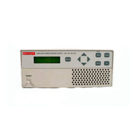
Keithley 2303B User Manual (152 pages)
high speed
Brand:
Keithley
| Category:
Power Supply
| Size: 1.2 MB
Table of Contents
Limitation of Warranty
2
Table of Contents
7
Getting Started
15
General Information
16
Warranty Information
16
Contact Information
16
Safety Symbols and Terms
16
Specifications
16
Getting Started
16
Inspection
17
Options and Accessories
17
Power Supply Overview
18
High Speed Power Supply
18
Getting Started
19
Remote Display Option
20
Power-Up
20
Line Power Connection
20
Fuse Replacement
21
Power-Up Sequence
21
Display Modes
22
Default Settings
23
Factory Defaults (RST)
23
Setups - Save, Power-On, and Recall
24
Menu
25
MENU Structure
26
Rules to Navigate MENU
27
SCPI Programming
27
Basic Power Supply Operation
29
Test Connections
30
Typical Connections
30
Basic Power Supply Operation
30
Outputting Voltage and Current
31
Setting Output Voltage and Current Limit
31
Output Capabilities
31
Current Ranges
32
Relay Control
34
Operate
36
SCPI Programming - Outputting Voltage and Current
36
SCPI Commands - Outputting Voltage and Current
36
Reading Back V and I
39
Actual V and I Display Mode
39
Measurement Configuration
39
SCPI Programming - Measure V and I, and DVM Input
40
SCPI Commands - Measure V and I, and DVM Input
40
Independent Voltage Measurements (DVM)
41
DVM Input Display Mode
41
Measurement Configuration
41
SCPI Programming - DVM
41
Sink Operation
42
Sink Operation Example
42
Sink Current Limits
42
Programming Examples
43
Outputting and Reading Back V and I
43
DVM Measurements
43
Basic Power Supply Operation
43
Pulse Current Measurements
45
Measurement Configuration
45
Overview
46
Trigger Level
47
Trigger Delay
47
Integration Times
47
Average Readings Count
47
Measurement Configuration
48
Current Range
48
Integration Times
48
Average Readings Count
49
Trigger Delay and Trigger Level
49
Pulse Current Display Mode
49
Pulse Current Measurement Procedure
50
Determining Correct Trigger Level (Pulse Current)
50
SCPI Commands - Pulse Current Measurements
51
Pulse Current Digitization
53
Programming Examples
54
SCPI Programming
51
Pulse Current Measurements
54
Long Integration Measurements
55
Overview
56
Integration Time
57
Trigger Edge
57
Trigger Level
57
Pulse Timeout
58
Measurement Configuration
58
Current Range
58
Integration Time
59
Pulse Timeout
59
Trigger Edge and Trigger Level
59
Long Integration Display Mode
60
Long Integration Measurement Procedure
60
General Notes
61
Determining Correct Trigger Level (Long Integration)
61
SCPI Programming
62
SCPI Commands - Long Integration Measurements
62
Programming Example
63
Long Integration Measurements
64
Relay Control
65
Overview
66
Relay Control
67
Connections
68
Miniature Phono Plug
68
Switchcraft Connection Accessories
68
Controlling the Relay
69
SCPI Programming
69
SCPI Command - Output Relay Control
69
Relay Control
70
GPIB Operation
71
General Bus Commands
71
Introduction
72
GPIB Bus Connections
72
GPIB Operation
72
IEEE-488 Connector
72
Primary Address
73
Output Format
73
General Bus Commands
74
REN (Remote Enable)
74
IFC (Interface Clear)
74
LLO (Local Lockout)
75
GTL (Go to Local)
75
DCL (Device Clear)
75
SDC (Selective Device Clear)
75
GET (Group Executive Trigger)
75
SPE, SPD (Serial Polling)
75
Front Panel Aspects of GPIB Operation
76
Remote Indicator and LOCAL Key
76
Error and Status Messages
76
Programming Syntax
77
Command Words
77
Program Messages
80
Response Messages
82
Message Exchange Protocol
82
Status Structure
83
Status Byte and Service Request
83
Overview
84
Status Byte and SRQ
84
Status Register Sets
84
Queues
84
Status Structure
84
Status Model Structure
85
Clearing Registers and Queues
86
Status Structure
86
Common and SCPI Commands - Reset Registers and Clear Queues
86
Programming and Reading Registers
87
Programming Enable Registers
87
16-Bit Status Register
87
Status Byte and Service Request (SRQ)
88
Status Byte Register
89
Service Request Enable Register
89
Serial Polling and SRQ
90
Status Byte and Service Request Commands
91
Command Commands - Status Byte and Service Request
91
Enable Registers
91
Status Register Sets
92
Register Bit Descriptions
92
Standard Event Status
93
Operation Event Status
94
Measurement Event Status
95
Questionable Event Status
96
Condition Registers
97
Event Registers
97
Common and SCPI Commands - Condition Registers
97
Common and SCPI Commands - Event Registers
97
Event Enable Registers
98
Common and SCPI Commands - Event Enable Registers
98
Programming Example - Program and Read Measurement Event Register
99
Queues
99
Output Queue
99
Error Queue
100
SCPI Commands - Error Queue
101
Common Commands
103
Overview
104
IEEE-488.2 Common Commands and Queries
104
IDN? - Identification Query
105
OPC - Operation Complete
105
OPC? - Operation Complete Query
105
SAV <Nrf> - Save
106
RCL <Nrf> - Recall
106
RST - Reset
106
TRG - Trigger
106
OPC and *OPC? Commands
106
TST? - Self-Test Query
107
WAI - Wait-To-Continue
107
Common Commands
108
Signal Oriented Measurement Commands
109
Overview
110
Fetch
110
Fetch:array
110
Signal Oriented Measurement Commands
110
Read
111
Read:array
111
Measure[:<Function>]
112
Measure:array[:<Function>]
112
Display, Format, and System
113
Display Subsystem
114
Display:enable <B
114
Display:text:data <A
114
Display, Format, and System
114
SCPI Commands - Display
114
Display:text:state <B
115
Format Subsystem
116
Format[:Data] <Type
116
SCPI Commands - Data Format
116
Display, Format, and System
117
IEEE-754 Single Precision Data Format
117
Format:border <Name
118
IEEE-754 Double Precision Data Format
118
System Subsystem
119
System:posetup <Name
119
SCPI Commands - System
119
SCPI Tables
121
SCPI Command Subsystems Reference Tables
122
11 SCPI Tables
123
Display Command Summary
123
Format Command Summary
123
Output Command Summary
123
Sense Command Summary
124
Source Command Summary
126
Status Command Summary
127
System Command Summary
128
Pulse Current Measurement
131
A Specifications
133
B Error and Status Messages
133
C Emulation Commands
137
100 C Emulation Commands
138
HP 6632A Power Supply Emulation Commands
138
HP Commands Used to Control the Power Supply
138
Fluke PM2811 Power Supply Emulation Commands
141
D Emulation Commands
141
Fluke Commands Used to Control Model 2303/2303B/2303-PJ
141
Selecting the 488.1 Protocol
144
Protocol Differences
145
General Operation Notes
146
Advertisement
Keithley 2303B Service Manual (104 pages)
Brand:
Keithley
| Category:
Power Supply
| Size: 0.91 MB
Table of Contents
Table of Contents
7
Performance Verification
12
Introduction
13
Verification Test Requirements
13
Environmental Conditions
13
Warm-Up Period
13
Line Power
14
Recommended Test Equipment
14
Resistor Connections
14
Recommended Verification Equipment
14
Resistor Considerations
15
Verification Limits
15
Example Limits Calculation
15
Test Resistor Connections
15
Performing the Verification Test Procedures
16
Test Summary
16
Test Considerations
16
Instrument Programming
16
Output Voltage Accuracy
16
Output Voltage Accuracy Limits
17
Voltage Readback Accuracy
18
Compliance Current Accuracy
18
Voltage Readback Accuracy Limits
18
Current Readback Accuracy
20
5A Range Readback Accuracy
20
Compliance Current Accuracy Limits
20
Models 2303 and 2303B 5Ma Range Readback Accuracy
21
Connections for Model 2303 and 2303B
21
5A Range Current Readback Accuracy Limits
21
Model 2303-PJ 500Ma Range Readback Accuracy
22
Model 2303 and 2303B 5Ma Range Current Readback Accuracy Limits
22
Digital Voltmeter Input Accuracy
24
Model 2303-PJ 500Ma Range Current Readback Accuracy Limits
24
Digital Voltmeter Input Accuracy Limits
25
Calibration
26
Introduction
27
Environmental Conditions
27
Temperature and Relative Humidity
27
Warm-Up Period
27
Line Power
27
Calibration Considerations
27
Calibration Cycle
28
Recommended Calibration Equipment
28
Resistor Connections
28
Resistor Considerations
29
Front Panel Calibration
29
Model 2303 Front Panel Calibration
29
Test Resistor Connections
29
Connections for Voltage Calibration
31
Connections for 5A Current Calibration
32
Connections for 5Ma Range Calibration
33
Calibration
34
Model 2303-PJ Front Panel Calibration
35
Connections for 500Ma Range Calibration
37
Calibration
38
Model 2303-PJ Front Panel Calibration Summary
38
Remote Calibration
39
Remote Calibration Commands
39
Remote Calibration Command Summary
39
Remote Calibration Display
40
Models 2303 and 2303B Remote Calibration Procedure
40
Models 2303 and 2303B Remote Calibration Summary
42
Model 2303-PJ Remote Calibration Procedure
43
Model 2303-PJ Remote Calibration Summary
45
Changing the Calibration Code
46
Changing the Code from the Front Panel
46
Changing the Code by Remote
46
Resetting the Calibration Code
47
Viewing Calibration Date and Count
47
Viewing Date and Count from the Front Panel
47
Acquiring Date and Count by Remote
47
Disassembly
48
Introduction
49
Handling and Cleaning
49
Handling PC Boards
49
Solder Repairs
49
Static Sensitive Devices
49
Assembly Drawings
50
Disassembly Procedures
50
Case Cover Removal
50
Analog Board Removal
51
Digital Board Removal
51
Front Panel Disassembly
51
Removing Mechanical Components
52
Instrument Re-Assembly
52
Replaceable Parts
54
Ordering Information
54
Factory Service
54
Parts Lists and Component Layouts
54
Models 2303 and 2303-PJ Parts Lists
55
Replaceable Parts
55
Models 2303 and 2303-PJ Digital Board Parts List
55
Models 2303 and 2303-PJ Analog Board Parts List
60
Models 2303 and 2303-PJ Display Board Parts
64
Models 2303 and 2303-PJ Mechanical Parts List
65
Model 2303B Parts Lists
66
Model 2303B Analog Board Parts List
71
Model 2303B Mechanical Parts List
75
Specifications
76
Accuracy Calculations
80
Output and Compliance Accuracy
80
Readback Accuracy
80
Digital Voltmeter Input Accuracy
80
B Calibration Reference Introduction
82
Command Summary
83
Remote Calibration Command Summary
83
Miscellaneous Commands
84
Calibration Step Summary
86
Detecting Calibration Errors
87
Reading the Error Queue
87
Error Summary
87
Status Byte EAV (Error Available) Bit
87
Calibration Errors
87
Generating an SRQ on Error
88
Detecting Calibration Step Completion
88
Using the *OPC Command
88
Using the *OPC? Query
88
Generating an SRQ on Calibration Complete
89
C Calibration Programs
90
Introduction
91
Computer Hardware Requirements
91
Software Requirements
91
Calibration Equipment
91
General Program Instructions
92
Instrument Control
97
Introduction
98
Front Panel Control
98
Setting the Display Mode
98
Selecting the Current Range
98
Turning on the Output
98
Setting Output Values
98
Setting the Reading Mode
99
Basic Remote Commands
99
Turning on the Output
100
Requesting Readings
100
Basic Control Program
100
Instrument Control
100
Advertisement
Related Products
Keithley 2302-PJ
Keithley 2302
Keithley 2306
Keithley 2306-VS
Keithley 2306-PJ
Keithley 2303
Keithley 2303-PJ
Keithley 2304a
Keithley 2220G-30-1
Keithley 2280S-32-6
Keithley Categories
Measuring Instruments
Multimeter
Power Supply
Test Equipment
Switch
More Keithley Manuals
Login
Sign In
OR
Sign in with Facebook
Sign in with Google
Upload manual
Upload from disk
Upload from URL