Table of Contents
Advertisement
Quick Links
Advertisement
Table of Contents

Subscribe to Our Youtube Channel
Related Manuals for CYP CMSI-48E


Summary of Contents for CYP CMSI-48E
- Page 1 CMSI-48E 4 by 8 Matrix Operation Manual Operation Manual...
- Page 3 DISCLAIMERS The information in this manual has been carefully checked and is believed to be accurate. Cypress Technology assumes no responsibility for any infringements of patents or other rights of third parties which may result from its use. Cypress Technology assumes no responsibility for any inaccuracies that may be contained in this document.
-
Page 4: Safety Precautions
SAFETY PRECAUTIONS Please read all instructions before attempting to unpack, install or operate this equipment and before connecting the power supply. Please keep the following in mind as you unpack and install this equipment: • Always follow basic safety precautions to reduce the risk of fire, electrical shock and injury to persons. -
Page 5: Table Of Contents
CONTENTS 1. Introduction ..........1 2. Applications ........... 1 3. Package Contents ........ 1 4. System Requirements ......2 5. Features ..........2 6. Operation Controls and Functions ..3 6.1 Front Panel ........3 6.2 Rear Panel .........4 6.3 Side Panel .........5 6.4 Remote Control ........6 6.5 IR Pin Assignment ......6 6.6 RS-232 Protocols .......7... -
Page 6: Introduction
1. INTRODUCTION The 4 by 8 Matrix allows HDMI signal from any of its four sources to be routed to any of its eight outputs simultaneously. With a thoughtful design for local and remote connections both required in system integration, the model is engineered with 4 HDMI and 4 CAT5e/6/7 outputs, the later ones carry major HDBaseT features including the transmission of high definition audio and video, bidirectional IR, RS-232 and PoC (Power over Cable) over 100 meters. -
Page 7: System Requirements
4. SYSTEM REQUIREMENTS • Input source equipment with HDMI connection cables • Industry CAT5e/6/7 cable • HDMI over CAT5e/6/7 Receivers with industrial CAT5e/6/7 cables • Output displays or audio receiver equipments with HDMI connection cables 5. FEATURES • Supports resolutions VGA to WUXGA and 480i to 1080p dependent upon the output display’s EDID settings •... -
Page 8: Operation Controls And Functions
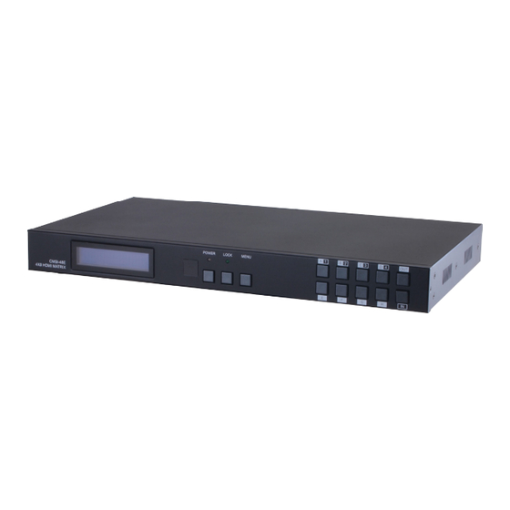
The following sections describe the hardware components of the unit. 6.1 Front Panel POWER LOCK MENU CMSI-48E 4X8 HDMI MATRIX LCM: This monitor displays your setting information with each input and output selection. IR: This IR window accepts the remote control signal of this device only. -
Page 9: Rear Panel
6.2 Rear Panel IR OUT IR IN IR OUT HDMI OUT CAT5e/6/7 OUT HDMI OUT CAT5e/6/7 OUT IR IN IR OUT IR IN IR OUT IR IN IR OUT HDMI OUT CAT5e/6/7 OUT HDMI OUT CAT5e/6/7 OUT IR IN HDMI IN 1 HDMI IN 2 HDMI IN 3 HDMI IN 4... -
Page 10: Side Panel
ALL IR OUT: Connect to the IR Blaster for IR signal transmission to the source side. Place the IR Blaster in direct line-of-sight of the equipment to be controlled for it will blaster out all signal received from the IR IN at the Receiver sides. ALL IR IN: Connect to the IR Extender for IR signal reception. -
Page 11: Remote Control
6.4 Remote Control Power: Press this button to switch ON the device or set it to standby mode. IN: Input ports selection 1~4. OUT: Output ports selection A~H. CR-110 6.5 IR Pin Assignment IR Blaster Power IR Blaster Signal IR Extender IR Signal Power Grounding... -
Page 12: Rs-232 Protocols
6.6 RS-232 Protocols CMSI-48E Remote Control Console Assignment Assignment Baud Rate: 19200bps Data bit: 8 bits Parity: None Flow Control: None Stop Bit: 1 6.7 RS-232 & Telnet Commands Command Description A1~A4 Switch output A to 1~4 B1~B4 Switch output B to 1~4... - Page 13 H1~H4 Switch output H to 1~4 A0~H0 Switch output A to F mute ABCD…1~ABCD…4 Switch output ABCD… to 1~4 ABCD….0 Mute output ABCD… at the same time SETIP<IP> <SubNet> Setting IP. SubNet. GateWay (Static IP) <GW> RSTIP IP Configuration Was Reset to Factory Defaults <DHCP>...
- Page 14 UARTSW0 Switch to MCU. Allowing Receivers to send commands to Matrix. UARTSW2 Switch to output B and allow Matrix to send commands to Receiver’s connected de- vice. UARTSW4 Switch to output D and allow Matrix to send commands to Receiver’s connected de- vice.
-
Page 15: Telnet Control
6.8 Telnet Control Before attempting to use the telnet control, please ensure that both the Matrix (via the 'IP & Ethernet' port) and the PC/Laptop are connected to the active networks. To access the telnet control in Windows 7, click on the 'Start' menu and type "cmd"... - Page 16 Type “IPCONFIG” To show all IP configurations. To reset the IP, type “RSTIP” and to use a set static IP, type ”SETIP” (For a full list of commands, see Section 6.7). Note: All the commands will be not executed unless followed by a carriage return.
-
Page 17: Webgui Control
6.9 WebGUI Control On a PC/Laptop that is connected to the active network as the Matrix, open a web browser and type device's IP address on the web address entry bar. The browser will display the device's status, control and User setting pages. Click on the 'Control' tab to control power, input/output ports, EDID and reset mode. - Page 18 Clicking on the 'User Setting' tab allows you to reset the IP configuration. The system will ask for a reboot of the device every time any of the settings are changed. The IP address needed to access the WebGUI control will also need to be changed accordingly on the web address entry bar.
-
Page 19: Connection Diagram
7. CONNECTION DIAGRAM 60° 1.5m 1.5m 60° RS-232 60° 60° Equipped PC 60° 60° or Notebook 60° 60° 1.5m IR1 Extender IR1 Extender HDMI Out HDMI Out 1.5m 1.5m 1.5m 1.5m 60° RS232 Out IR2 Blaster RS232 Out IR2 Blaster 60°... -
Page 20: Specifications
8. SPECIFICATIONS Video Bandwidth 225MHz/6.75Gbps Input Ports 4 x HDMI, 5 x IR Extender, 1 x RS-232, 1 x LAN (Control only), 1 x RJ45 (Control Only), 1 x USB Mini-B (Service Only) Output Ports 4 x HDMI, 4 x CAT5e/6/7, 5 x IR Blaster Power Supply 24V / 3.75A DC (US/EU standards, CE/ FCC/UL certified) -
Page 21: Input Timing Support Chart
8.2 Input Timing Support Chart HDMI Supported Input Resolutions Vertical Pixel HDMI Video Resolution Timing Frequency(Hz) Rate (MHz) Support Standard 640x480@60 60.00 25.175 VESA 31.500 VESA 640x480@72 72.00 31.500 VESA 640x480@75 75.00 36.000 VESA 640x480@85 85.00 35.500 VESA 720x400@85... - Page 22 108.000 VESA 1280x1024@60 60.00 85.500 VESA 1360x768@60 60.00 85.500 — VESA 1366x768@60 60.00 101.000 VESA 1400x1050@60RB 60.00 121.750 VESA 1400x1050@60 60.00 88.750 — VESA 1440x900@60RB 60.00 106.500 — VESA 1440x900@60 60.00 108.000 — VESA 1600x900@60 60.00 162.000 —...
-
Page 23: Acronyms
74.176 1280x720p@59.94 59.94 74.250 1280x720p@60 60.00 74.250 1920x1080i@50 50.00 74.176 1920x1080i@59.94 59.94 74.250 1920x1080i@60 60.00 148.500 1920x1080p@50 50.00 148.352 1920x1080p@59.94 59.94 148.500 1920x1080p@60 60.00 74.176 1920x1080p@23.97 23.97 74.250 1920x1080p@24 24.00 74.250 1920x1080p@25 25.00... - Page 24 CYPRESS TECHNOLOGY CO., LTD Home page: http://www.cypress.com.tw MPM-CMSI48E...
Need help?
Do you have a question about the CMSI-48E and is the answer not in the manual?
Questions and answers