Table of Contents
Advertisement
Quick Links
Advertisement
Table of Contents

Related Manuals for Iso-Tech IDM 507


Summary of Contents for Iso-Tech IDM 507
- Page 1 Instruction Manual IDM 507 Process Multimeter IDM 507 ...
-
Page 2: Safety Information
Safety sheet Warning Warning Safety sheet ........ -
Page 3: Unsafe Voltage
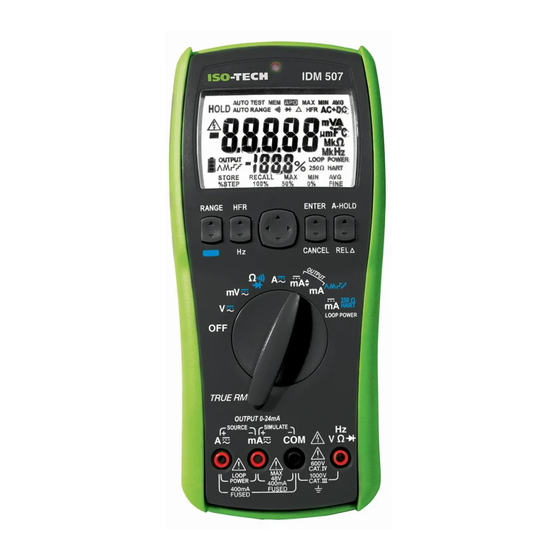
CAUTION ˙ Disconnect the test leads from the test points before chang- ing the position of the function rotary switch. ˙ Never connect a source of voltage with the function rotary switch in Ω, A, Loop-Power position. ˙ Do not expose Meter to extremes in temperature or high humidity. - Page 4 The Meter Description Front Panel Illustration 1. LCD display: 50,000 counts. 2. Push buttons for features. 3. Rotary switch for turn the power on / off and select the function. 4. Input terminal for A function / Loop-Power mode + / source mode +.
-
Page 5: Making Basic Measurements
Making Basic Measurements Preparation and Caution Before Measurement : Observe the rules of Warnings and Cautions When connecting the test leads to the DUT (Device Under Test) connect the common (mA) test lead before connecting the live lead;... -
Page 6: Measuring Voltage
Measuring Voltage ˙ Press the Function button to select the presently measuring function (AC / DC / AC+DC). ˙ Press the Function button > 1 sec to enter the auto test mode, and press again to exit this mode. ˙ The auto test mode can automatically determine the voltage / current which is AC or DC. -
Page 7: Measuring Current
Measuring Current ˙ The basic operations are same as voltage function. Measuring Frequency ˙ When measuring voltage or current, press the Hz button to measuring the frequency for voltage or current. ˙ Press the Hz button again to exit this mode. High Frequency Reject (Low Pass Filter) ˙... -
Page 8: Measuring Resistance
Measuring Resistance ˙ Press the Function button to select the presently measuring function (Ω / Continuity Check / Diode Test). Continuity Check ˙ Press the Function button to select continuity check when the rotary in resistance position. ˙ The buzzer allows you to quickly continuity tests without watching the display. -
Page 9: Diode Test
Diode Test ˙ Press the Function button to select diode test when the ro-tary in resistance position. ˙ In diode test, you can test direction and forward voltage. ˙ If the DUT was not a diode (Open, Short, Resistance or Capacitance), the display showed “-----”. -
Page 10: Dc Current Output
DC Current Output ˙ To use the DC current output function, turn the rotary in output position (Adjustable DC output or Auto DC output). ˙ The DC current output function has both modes: Source Mode & Simulate Mode ˙ The output mode has both types: 0-20mA & 4-20mA. That is selectable. -
Page 11: Source Mode
Source Mode ˙ When meter in the source mode, it provided internal power supply (Batteries > 4.5V) to drive the DC current output. ˙ To operate in the source mode, put the both probes in A terminal (Source +) and mA terminal (Source -). Then the meter will automatically enter the source mode. -
Page 12: Simulate Mode
Simulate Mode ˙ When meter in the simulate mode, it used external power supply (12V to 48V) to drive the DC current output. ˙ To operate in the simulate mode, put the both probes in mA terminal (Simulate +) and COM terminal (Simulate -). Then the meter will automatically enter the simulate mode. -
Page 13: Loop Power
Loop Power ˙ In this function, the meter provided internal power supply to output > 24V / 20mA. ˙ To operate in the loop power function, put the probes in A terminal (Source +) and mA terminal (Source -). Then the meter will automatically drive. - Page 14 Auto Hold ˙ Press the A-HOLD button to start the auto hold mode, and press again to exit. ˙ In this mode, the meter show the indication “HOLD” on the display. ˙ When the difference is bigger (> 50d) than hold data, and it is also stable.
-
Page 15: Store / Recall
Store / Recall ˙ When blink cursor of menu is STORE, press the ENTER button to store the presently reading to memory. ˙ The meter can store maximum 100 data in the memory. ˙ You can enter the recall mode to review the stored data. ˙... -
Page 16: Power On Options
Power On Options When turn the power on, press the function button to execute the below options. Button Action Select the output type (0-20mA & 4-20mA) RANGE and set it to default. FUNCTION Disable APO. Show the firmware version. Enable / Disable the buzzer and set the ENTER option to default. -
Page 17: Battery And Fuse Replacement
Battery and Fuse Replacement Refer to the following figure to replace fuse and the batteries : ˙ Be always replaced the batteries & fuse that conform the specifications. ˙ Battery Type: 4 x 1.5V IEC LR6 or AA size ˙ Fuse Type: 2 x 440mA, 1000V IR 10kA Fuse (Bussmann DMM-B-44/100) ˙... -
Page 18: Specifications
Specifications General Specifications Maximum voltage applied to any terminal : 1000V or 1000V Display : 50,000 counts, over range to 110%. Polarity Indication : Automatic, positive implied, negative indicated. Over Range Indication : OL Measuring Rate : 10 samples per second Power Requirements : 4 x 1.5V IEC LR6 or AA size Battery Life: 100 hours Low Battery Indication : “... -
Page 19: Electrical Specifications
Electrical Specifications ˙ Accuracy is ± (% reading + number of digits) ˙ Ambient temperature: 23°C ± 5°C (< 80% RH) ˙ For the best measurements, with REL Δ function to compensate for offsets. 1. Voltage Function Range Accuracy Sine Wave: 50.000mV ±... - Page 20 2. Current Function Range Accuracy Sine Wave: 50.000mA ± (1.0% + 20d) for 40Hz to 70Hz 1.000A ± (2.0% + 40d) for 71Hz to 10kHz 50.000mA ± (0.05% + 5d) 1.000A [1] Below 5% of AC range, add 20d to accuracy. Input Protection : Equipped with High Energy Fuse.
- Page 21 5. Resistance Range Resolution Output Current Accuracy 500.00Ω 0.01Ω ± (0.2% + 30d) 5.0000kΩ 0.1Ω 100uA ± (0.2% + 10d) 50.000kΩ 1Ω 10uA 500.00kΩ 10Ω ± (0.5% + 10d) 5.0000MΩ 100Ω 100nA ± (1.0% + 10d) 50.00MΩ 10kΩ 10nA ± (2.0% + 10d) [1] There is a little rolling less than <...
- Page 22 9. Auto DC Current Output Range Resolution Accuracy 0.000mA to 20.000mA Over range to 24.000mA ± (0.5% + 5d) 4.000mA to 20.000mA Over range to 24.000mA Input Protection : Equipped with High Energy Fuse. 440mA, 1000V IR 10kA Fuse (Bussmann DMM-B-44/100) Power Source : Source Mode : Internal batteries, >...
-
Page 23: Limited Warranty
Limited Warranty This meter is warranted to the original purchaser against defects in material and workmanship for 3 years from the date of purchase. During this warranty period, RS Components will, at its option, replace or repair the defective unit, subject to verification of the defect or malfunction. - Page 24 Asia Iso-Tech 460 Alexandra Road, #15-01A PSA Building Singapore 119963 7410 Pebble Drive Fort Worth Texas 76118-6961 Europe Iso-Tech PO Box 99 Corby Northamptonshire NN17 9RS United Kingdom Canada 1701 Woodward Drive Ste 108 Ottawa Ontario K2C 0R4, Canada Japan...
Need help?
Do you have a question about the IDM 507 and is the answer not in the manual?
Questions and answers