Table of Contents
Advertisement
Advertisement
Table of Contents

Related Manuals for Iso-Tech IDM63N


Summary of Contents for Iso-Tech IDM63N
- Page 1 INSTRUCTION MANUAL IDM63N DIGITAL MULTIMETER...
- Page 2 ISO-TECH IDM 63N DIGITAL MULTIMETER INSTRUCTION MANUAL...
- Page 4 INTRODUCTION 1-1 Unpacking and Inspection Upon removing your new Digital Multimeter from its packing, you should have the following items: 1. Digital Multimeter. 2. Test lead (one black, one red). 3. Instruction Manual. 1-2 Meter Safety Terms as Marked on Equipment ATTENTION —...
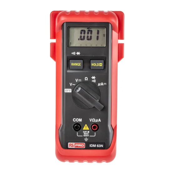
- Page 5 1-3 Front Panel Refer to Figure 1 and to the following numbered steps to familiarize yourself with the meter's front panel controls and connectors. 1. Digital Display — The digital display has a 3200 counts LCD readout with 65 segments analog bar graph, auto ...
- Page 6 Figure 1...
- Page 7 SPECIFICATIONS 2-1 General Specifications This instrument has been designed in accordance with UL 3111 and IEC publication 1010 Pt 1, Class II, Safety Requirements for Electrical Equipment for Measurement, Control and Laboratory use. This level of safety can only be guaranteed while the limits of section 2.2 are observed. Display : The Liquid Crystal Display (LCD) has a maximum reading of 3200, and 65 segments bar graph.
- Page 8 2-2 Environmental Conditions: Indoor use. Maximum Altitude : 2000 meters. Installation Category : IEC 1010 600V, Cat III. Pollution Degree : 2 Operating Temperature : 0°C ~ 30°C (≦ 80% R.H), 30°C ~ 40°C (≦ 75% R.H), 40°C ~ 50°C (≦ 45% R.H). Storage Temperature : -20°C to 60°C, 0 to 80% R.H with battery removed from the meter.
- Page 9 2-3 Electrical Specifications Accuracy is ± (% reading + number of digits) at 23°C ± 5°C less than 80% R.H. (1) DC Volts Range Resolution Accuracy Over voltage protection 100µV 300mV 10mV ±(0.5%reading + 2digits) 600V DC or 600V rms 300V 100mV 600V...
- Page 10 (2) AC Volts Range Resolution Accuracy Over voltage protection * ±(1.5%reading + 5digits) 10mV 600V DC or 600V rms ±(1.5%reading + 5digits) 300V 100mV 40Hz to 500Hz 600V * Frequency Response : 40Hz ~ 300Hz for 3V Range. Input Impedance : 10MΩ //less than 100PF. The reading will fluctuate approximately 2 ~ 5 counts over 200V.
- Page 11 (3) Resistance Range Resolution Accuracy Overload Protection 300Ω 0.1Ω ±(1.0%reading + 4digits) 3KΩ 1Ω 30KΩ 10Ω 600V DC or 600V rms ±(0.8%reading + 2digits) 300KΩ 100Ω 3MΩ 1KΩ 30MΩ 10KΩ ±(2.0%reading + 5digits) Open Circuit Voltage: 1.3V approx.
- Page 12 (4) Diode Check and Continuity Max. Open Range Resolution Accuracy Max. Test Current Circuit Voltage 1.5mA 3.3V * ±(1.5%reading + 5digits) *For 0.4V ~ 0.8V. Overload Protection: 600V DC/AC rms max. Continuity: Internal sounder operates when resistance is less than approximately 20Ω.
- Page 13 (5) DC µ A Overload Range Resolution Accuracy Burden Voltage Protection 300µA 0.1µA 600V rms or <4.5mV / µA @25°C ±(1.0%reading + 2digits) 3200 µA rms 3000µA 1µA (6) Auto Power Off The meter will automatically shut off, approximately 10 minutes after power on. The meter can be turned back on by pressing the "RANGE"...
- Page 14 OPERATION This instrument has been designed and tested in accordance with IEC Publication 1010, Safety Requirements for Electronic Measuring Apparatus, and has been supplied in a safe condition. This instruction manual contains some information and warnings which must be followed by the user to ensure safe operation and to retain the instrument in safe condition.
- Page 15 TEST EQUIPMENT RISK ASSESSMENT (UK RECOMMENDATION) Users of this equipment and/or their employers are reminded that Health and Safety legislation require them to carry out valid risk assessments of all electrical work so as to identify potential sources of electrical danger and risk of electrical injury such as from inadvertent short circuits.
- Page 16 UNSTABLE DISPLAY MAY OCCUR ESPECIALLY ON THE 300mV RANGE, EVEN IF THE TEST NOTICE : LEADS ARE NOT CONNECTED TO THE METER. IN THIS CASE, IF AN ERRONEOUS READING IS SUSPECTED, SHORT THE "VΩ" TERMINAL AND THE "COM" TERMINAL AND MAKE SURE THE DISPLAY READS ZERO.
- Page 17 3-5 Diode Check 1. Set the function switch at " " position. 2. Connect the black test lead to the "COM" terminal and the red lead to "VΩ µA" input terminal. 3. Connect the test leads to the diode. Normally the forward voltage drop of a good silicon diode is between 400V to .900V.
- Page 18 MAINTENANCE To keep the instrument clean, wipe the case with a damp cloth and detergent, do not use abrasives or solvents. Any adjustment, maintenance and repair of opened instrument with voltage applied should be avoided as far as possible and, if inevitable, shall be carried out by a skilled person who is aware of the hazard involved. Whenever it is likely that the protection has been impaired, the instrument must be made inoperative and be secured against any unintended operation.
- Page 19 BATTERY REPLACEMENT The meter is powered by a two 1.5V battery. Refer to Figure 2 and use the following procedure to replace the battery: 1. Disconnect the test leads and turn the meter off. Remove the test leads from the input terminals. 2.
- Page 20 BATTERY REPLACEMENT Case Bottom 1.5V x 2 Battery Case Top Battery Box Battery Connector Figure 2...
- Page 21 HOW TO USE THE PROBE HOLDER Slide out one probe holder for one handed meter operation.
- Page 22 HOW TO USE THE PROBE HOLDER Wrap the leads around the holster to store the test probes.
- Page 23 HOW TO USE THE TILT STAND AND HOLSTER Swing the stand out for Swing the upper holder out Hang on a nail at the workbench. easier meter reading. and hook it over a door.
- Page 24 Asia Iso-Tech 7410 Pebble Drive 460 Alexandra Road, #15-01A Fort Worth PSA Building Texas 76118-6961 Singapore 119963 Europe Canada Iso-Tech 1701 Woodward Drive PO Box 99 Ste 108 Ottawa Corby Ontario K2C 0R4, Canada Northamptonshire NN17 9RS United Kingdom Japan...
Need help?
Do you have a question about the IDM63N and is the answer not in the manual?
Questions and answers