Advertisement
Table of Contents
- 1 Limited Warranty
- 2 Table of Contents
- 3 Warning" and " Caution" Alert Symbol Statements
- 4 Unpacking and Inspection
- 5 Environmental Conditions
- 6 Warning and Cautions
- 7 Testing for Diode and Continuity
- 8 Measuring Capacitance
- 9 Features Description
- 10 Display Hold
- 11 Auto Power off (Battery Saver)
- 12 Cleaning and Storage
- 13 Fuse Replacement
- 14 Trouble Shooting
- 15 General Specifications
- 16 Electrical Specification
- Download this manual
Advertisement
Table of Contents

Subscribe to Our Youtube Channel
Related Manuals for Iso-Tech IDM 103N


Summary of Contents for Iso-Tech IDM 103N
- Page 1 Instruction Manual IDM 103N/105N/106N Digital Multimeter...
- Page 2 ISO-TECH IDM 103N/105N/106N DIGITAL MULTIMETER INSTRUCTION MANUAL...
-
Page 3: Limited Warranty
Safety Alert Symbol : READ and UNDERSTAND all Warning Caution ....safety alert symbols : ... -
Page 4: Table Of Contents
Title Page Safety ……………………………………………………………. ” Warning” and “ Caution” Alert Symbol Statements …… Warning and Cautions …………………………………………. Symbols as Marked on The Meter …………………………… Symbols and Terms in The Manual ………………………….. Safety Compliance And Certification ……………………… Safety Compliance ……………………………………………… Safety Certification ……………………………………………… Introduction …………………………………………………….. -
Page 5: Warning" And " Caution" Alert Symbol Statements
Safety " Warning" and " Caution" Alert Symbol Statement : Warning" " Alert Symbol A " Warning" Statement identifies hazardous conditions and actions that could cause BODILY HARM or DEATH. Caution" " Alert Symbol Caution" Statement: identifies A " conditions and actions that could DAMAGE the Meter or the equip- ment under test. - Page 6 ․ Use the Meter only as specified in this manual or the protection by the Meter might be impaired. ․ Always use proper terminals, switch position, and range for measurements. ․ Never attempt a voltage measurement with the test lead inserted into the A input terminal. ․...
- Page 7 Cautions ․ Disconnect the test leads from the test points before changing the position of the function rotary switch. ․ Never connect a source of voltage with the function rotary switch in Ω/ mA / /Hz position. ․ Do not expose Meter to extremes in temperature or high humidity.
- Page 8 Symbols and Terms in The Manual Symbols : : Caution, Risk of Danger. Warning : To identifies hazardous conditions and actions that could cause BODILY HARM or DEATH Caution : To identifies conditions and actions that could DAMAGE the meter or equipment under test. : Fuse.
- Page 9 PER IEC1010 Pollution degree POLLUTION Addition of foreign matter, solid, liquid or gaseous (ionized gases), that may produce a reduction of dielectric strength or surface resistivity. POLLUTION degree For the purpose of evaluating spacing of this product, the following degrees of POLLUTION in the microenvironment are defined.
-
Page 10: Unpacking And Inspection
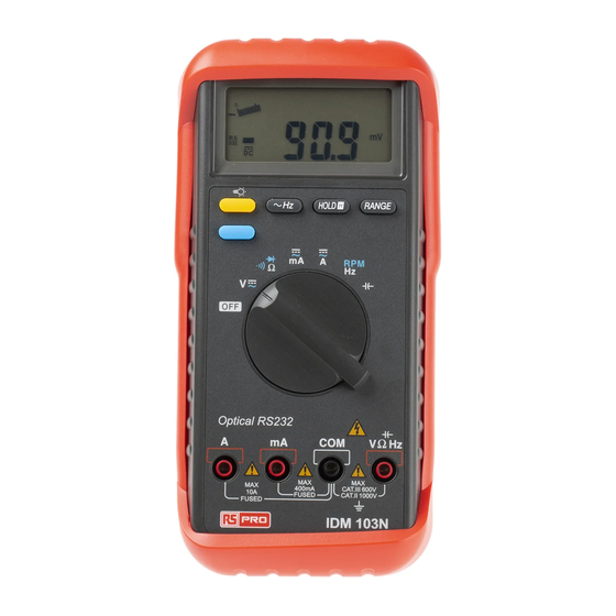
Introduction Unpacking and Inspection Upon removing your new Digital Multimeter from its packing, you should have the following items. 1. Digital Multimeter. 2. Test lead set (one black, on red) 3. User Manual. 4. Protective holster. Environmental Conditions This product is safe at least under the following conditions: 1. - Page 11 The Meter Description Front Panel Illustration 1. 4000 counts LCD display. 2. Push-buttons for features. 3. Rotary switch to turn the Power On or Off and to select a function. 4. Input Terminal for A current function 5. Input Terminal for all functions EXCEPT current (A) functions 6.
-
Page 12: Warning And Cautions
Making Basic Measurements Preparation and Caution Before Measurement : Observe the rules of Warnings Cautions When connecting the test leads to the DUT (Device Under Test) connect the common (COM) test lead before connect- ing the live lead ; when removing the test leads removing the test live lead before removing the common test lead. - Page 13 Measuring AC/DC Voltage And Frequency...
- Page 14 Note – When measuring voltage, the Meter acts like a 10MΩ impedance in parallel with the circuit under test. This loading effect of the 10MΩof the Meter can cause measurement errors, loading efffect error, Especially in high impedance cir- cuits. For example : A 1.1M impedance circuit will cause a –10% measuring error.
- Page 15 Measuring Resistance Caution To avoid possible damage to the Meter or to the equip- ment under test, disconnect circuit power and discharge all high-voltage capacitors before measuring resistance. Note – The Meter provides a open voltage ≦–1.5V to the circuit under test that cause the diode, transistor junction to conduct so it is batter to disconnect the resistance from the circuit to get a correct measurement.
-
Page 16: Testing For Diode And Continuity
Testing for Diode and Continuity Diode : Bad! Good! Good! Continuity : Caution For in-circuit test, turns circuit power off and Discharge the high-voltage capacitors through an appropriate resistance load. - Page 17 Note – Use the diode test to check the semiconductor junction is good or bad. The Meter sends a current through the semiconductor junction to measures the voltage drop across the junction. A good junction drops between 0.4 V to 0.9 V. Measuring DC mA, AC mA, DC A, AC A Current And Frequency ...
- Page 18 Caution To avoid possible damage to the Meter or to the equip- ment under test, check the Meter’s fuses before measur- ing current. Use the proper terminals, function, and range for your measurement. Never place the probes across (in parallel with) any circuit or component when the leads are plugged into the current terminals.
- Page 19 Making Basic Measurements Measuring Hz / RPM Note – Connect the red test lead to the “ VΩHz ” terminal and the other (black) test lead to the “COM” terminal. Set the rotary function selector to “Hz RPM” position to meas- ure the frequency or RPM with the blue switch.
-
Page 20: Measuring Capacitance
Measuring Capacitance Caution To avoid possible damage to the meter or to the equip- ment under test, disconnect circuit power and discharge all high-voltage capacitors before measuring capacitance. Use the DC voltage function to confirm that the capacitor discharged. Note–... - Page 21 Measuring Temperature (Model 106 only) Vent Sensor K Type C115 Pipe Sensor K Type C115 Caution Do not Connect senor K Type C115 (Bead probe) to live Circuits.
-
Page 22: Features Description
Features Features Feature Description The Meter has Features : Display Hold – To freezes the display. Min Max Hold – To record the Max or Min reading of the display. Peak – To record the Max or Min reading of the display. REL △... - Page 23 Features Available vs Functions °C DCmA Ω °F ACmA Light Key PEAK RANGE Blue Key MIN Max REL △ HOLD Using The Features Manual Ranging and Auto Ranging...
- Page 24 Using The Features Note - The Range button is pressed to select manual ranging and to change ranges. When the Range button is pressed once, the RANGE indicator turns off. Press Range button to select the appropriate range for measurement you want to make.
-
Page 25: Display Hold
Using The Features Note – Press HOLD button in MIN MAX mode makes the Meter stop updating the maximum and minimum value. When display Hold mode is nested in MIN MAX mode, to release MIN MAX mode is needed to release display hold first. REL △... -
Page 26: Auto Power Off (Battery Saver)
Using The Features Backlight Note – Press the Backlight Button to toggle in and out the display backlight. Auto Power Off (Battery Saver) Note – If the Meter idles for more than 30 minutes, the Meter automatically turns the power off. When this happens, the LCD displaying-state of the Meter is saved, the Meter can be turns back on by pushing any buttons, the LCD display the saved state when auto power off itself, pushing Hold button to... -
Page 27: Cleaning And Storage
Maintenance Disable Auto Power Off Maintenance Caution ․ Do not attempt to repair this meter. It contains no user- serviceable parts. Repair or servicing should only be performed by qualified personal. Failure to observe this precaution can result in injury ․... -
Page 28: Fuse Replacement
Fuse Replacement Refer to Figure xx to replace fuse : Caution ․ Use Two fuses with the amperage, interrupt, voltage, and speed rating specified. ․ Fuse rating : 1A, 600V, Fast. Fuse rating : 15A, 600V, Fast. Battery Replacement Refer to Figure xx to replace the battery : ... -
Page 29: Trouble Shooting
Trouble Shooting Do not attempt to repair your Meter unless you are qualified to do so and have the relevant calibration, performance test and service information. Basicc Trouble Shooting If the Meter fails, fist check the battery, the loose of battery and battery snap, fuse, test leads, replace as necessary. -
Page 30: General Specifications
Specification Specification General Specifications Display : The Liquid Crystal Display (LCD) with a maximum reading of 4000 and 82 segments bar graph. Polarity Indication : Automatic, positive implied, negative indicated. Overrange Indication : “OL” or “-OL” Low Battery Indication : “ ” is displayed when the battery voltage drops below operating voltage. -
Page 31: Electrical Specification
Electrical Specifications Accuracy is ± (% reading + number of digits) at 23ºC ± 5ºC , less than 80% R.H. (1) DC Volts Accuracy Range 103N 105N/106 ±(0.3% + 2dgt) ±(0.3% + 2dgt) 400.0mV 4.000V ±(0.4% + 2dgt) 40.00V ±(0.1% + 2dgt) ±(0.25% + 2dgt) 400.0V 1000V... - Page 32 Over voltage protection : 1000V rms Input Impedance : 10MΩ // less than 100pF. CMRR / NMRR : (Common Mode Rejection Ratio) (Normal Mode Rejection Ratio) : CMRR > 60dB at DC, 50Hz / 60Hz : CMRR > 100dB at DC, 50Hz / 60Hz NMRR >...
- Page 33 (4) AC Current Accuracy Voltage Range Burden 103N 105N/106 40.00mA 300mV max ±(1.5% + 5dgt)* ±(1.5% + 5dgt)* 400.0mA 3V max 10.00A ±(2.5% + 5dgt) ±(2.0% + 5dgt) 3V max Frequency Response : 40Hz ~ 1KHz. AC Conversion Type : 103N / 105N : Average sensing rms indication.
- Page 34 (5) Resistance Accuracy Range 103N 105N/106 ±(0.7% + 3dgt) ±(0.7% + 3dgt) 400.0Ω 4.000KΩ 40.00KΩ ±(0.4% + 2dgt) ±(0.6% + 3dgt) 400.0KΩ 4.000MΩ ±(0.7% + 3dgt) ±(0.6% + 3dgt) ±(1.5% + 5dgt) ±(1.5% + 5dgt) 40.00MΩ Open circuit Voltage : -1.3V approx. (6) Diode Check and Continuity Range Resolution...
- Page 35 (7) Frequency / RPM Range Sensitivity Accuracy 4.000KHz / 40.00KRPM Frequency : 150mV rms ≧ 20Hz 40.00KHz / 400.0KRPM ±(0.01% + 1dgt) 1.5V rms ≦ 20Hz 400.0KHz / 4.000KRPM 4.000MHz / 40.00MRPM 300mV rms RPM : ±(0.01% + 40.00MHz / 400.0MRPM 1V rms 10dgt) 400.0MHz / 4.000MRPM...
- Page 36 * In these two ranges the reading maybe rolling within speci- fication. ** specify reading <half of full scale range. (9) Temperature (ºC ) for 106 only Overload Temperature Accuracy Protection ±(2% + 4°C) -20°C ~ 0°C ±(1% + 3°C) 1°C ~ 100°C 600V rms 101°C ~ 500°C...
- Page 37 (11) PEAK HOLD Function Range Accuracy 400mV Unspecified ±(1.5% + 300dgt) 2* ±(1.5% + 60dgt) 400V 1000V 400mV Unspecified ±(1.5% + 300dgt) 2* ±(1.5% + 60dgt) 400V 750V 40mA ±(3.0% + 60dgt) DCA / ACA 400mA 3* ±(1.5% + 60dgt) Note : 1.
- Page 38 Asia Iso-Tech 460 Alexandra Road, #15-01A PSA Building Singapore 119963 7410 Pebble Drive Fort Worth Texas 76118-6961 Europe Iso-Tech PO Box 99 Corby Northamptonshire NN17 9RS United Kingdom Canada 1701 Woodward Drive Ste 108 Ottawa Ontario K2C 0R4, Canada Japan...
Need help?
Do you have a question about the IDM 103N and is the answer not in the manual?
Questions and answers