Advertisement
Quick Links
Advertisement

Related Manuals for Iso-Tech IDM101


Summary of Contents for Iso-Tech IDM101
- Page 1 Instruction Manual IDM101 Digital Multimeter...
- Page 2 ISO - TECH IDM101 Digital Multimeter INSTRUCTION MANUAL...
-
Page 4: Safety Notes
1. Safety notes This meter has been produced to comply with category II requirements under IEC publication 1010-1 "Safety requirements for electrical equipment for measuring, monitoring and laboratory use". The present operating manual gives directions which must be followed and points out precautions which must be taken if the meter is to be used safely and kept in a safe state. - Page 5 Important : To avoid damage to the meter, – remove the probes from the item being measured before you change the function settings, – never try to measure voltages which may exceed 600V or 600Vrms, – and never try to measure voltages when the meter is set to the resistance measuring function (Ω). Always use the fuses specified.
- Page 6 2. Introduction This multimeter is a compact, battery-powered, handheld measuring and testing device for service engineers, industrial use and amateur electronics engineers and for testing and repairing pieces of equipment. The functions it can perform are as follows: Measurement of a.c. and d.c. voltages Measurement of a.c.
- Page 7 3. Technical specification 3.1 General specification This meter has been produced to comply with category II requirements under IEC publication 1010-1 "Safety requirements for electrical equipment for measuring, monitoring and laboratory use". This standard of safety can only be guaranteed if the maximum and minimum figures specified in section 2.2 are observed.
-
Page 8: Electrical Specification
Dimensions (L x B x H(mm)) : 185 x 86 x 32, with rubber holster: 200 x 98 x 52 Weight (inc. batteries) : 0.37kg with rubber holster 0.6kg Accessories : Rubber holster, test leads, batteries (fitted) and operating manual. 3.3 Electrical specification Accuracy is given as ±... - Page 9 3.3.2 A.c. voltage (Va.c.) Over Voltage Range Resolution Accuracy protection 1µV ±(1% + 5D) 10µV 50 to 60Hz 600Vd.c. or 600V rms 400V 100mV ±(1.5% + 5D) 50 to 60Hz 600V Input impedance: 10M Ω in parallel with less than 100pF. A.c.
- Page 10 3.3.4 A.c. current (Aa.c.) Range Resolution Accuracy Voltage drop 1µA ±(1.5% + 5D) 40mA 10µA 800mV (max.) 40Hz to 1KHz 400mA 0.1mA ±(2.5% + 5D) 10mA 1V (max.) 40Hz to 1KHz Overload protection : mA jack: 1A/415V, 32 x 6.35mm quick-acting fuse. A input terminal : 10A/415V, 32 x 6.35mm quick-acting fuse.
- Page 11 3.3.6 Capacitance Range Resolution Accuracy Overload protection ±(1% + 40D) 40nF 10pF 600Vd.c. or ±(1% + 4D) 400nF 100pF 4µF 600V rms ±(1% + 4D) < 20µF 40µF 10nF ±(5% + 8D) > 20µF Continuity testing: Indication threshold : Approx. 40 Ω Continuity indication : 2kHz tone Input protection : 600Vor 600Vrms Diode testing:...
-
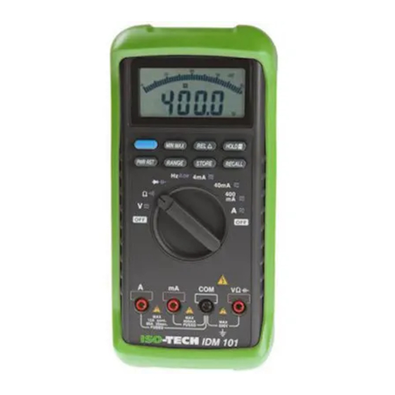
Page 12: Display And Connections
ADAPT range (ADP) Indication : 10 units of the lowest digit per mV. Accuracy : ±(0.3% + 2D) Input protection : 600Vd.c. or 600Vrms 4. Display and connections The display, controls and test jacks are shown in Fig.1. 1. Digital display — The 33⁄4 digit 3999 count digital LCD display includes a 42-element analog bargraph display and has automatic annunciators for polarity, decimal point, range overrun, store data, AC/DC, Ω/ "... - Page 13 By pressing the "Hold" button in the MIN/MAX mode you can stop the measurements from being recorded and by pressing it again you can allow their recording to continue. If you stop the recording, the current measurement shown is held and the bargraph display frozen.
- Page 14 13. Store button — In the store mode, "MEM" appears on the display and the last measurement made is stored. The value stored is not deleted when the meter switches itself off automatically, but it is when the rotary switch is turned to "Off". 14.
- Page 15 Figure 1...
- Page 16 5. Using the meter The meter was produced and tested to comply with IEC publication 1010 "Safety requirements for electrical equipment for measuring, monitoring and laboratory applications" and was in a reliable state when supplied. This operating manual gives directions and warnings which are essential for the user to follow, to work safely and to ensure the integrity of the meter.
- Page 17 5.3 Measuring currents 1. Plug the black lead into the "COM" input terminal of the meter. To measure currents up to a maximum of 400 mA plug the red lead into the "mA" input terminal and to measure currents up to a maximum of 10A plug it into the "A" input terminal. (The meter can also measure and display currents of up to 20A but currents of this level must not be applied to it for more than 30 seconds.) 2.
- Page 18 5.5 Continuity testing with the internal sounder 1. Plug the black lead into the "COM" input terminal and the red lead into the "V Ω " input terminal. 2. Turn the function switch to "Ω” and use the function button to set to continuity testing (" " will appear on the display). 3.
-
Page 19: Changing Batteries
5.8 Measuring frequencies 1. Plug the black lead into the "COM" input terminal and the red lead into the "V -Ω- " input terminal. 2. Turn the function switch to "Hz ADP" and use the function button to select frequency measurement (Hz). 3. - Page 20 Bottom half of case 1.5V battery Top half of case Battery holder Fig.2 Changing batteries...
- Page 21 7. Changing the fuses To change the fuses, see Fig.3 and follow the instructions given below. 1. Carry out steps 1 to 5 of the instructions for changing the batteries. 2. Lift the printed circuit board out of the top half of the case. Do not remove any of the screws from the printed circuit board.
- Page 22 Top half of case 10A/415V fuse Fuse holder Bottom half of case 1A/415V fuse Fig.3 Changing fuses...
- Page 23 8. Looking after the meter To clean the meter, wipe it over with a soft cloth and a mild detergent. Never use scouring cleansers or solvents. As far as possible, no settings should be made on the meter and no servicing or repair work should be done on it while it is opened up and switched on.
- Page 24 9. Using the probe holders To work one-handed, clip one of the probes into To store the probes safely, wind the leads around the rubber a probe holder. holster and clip the probes into the probe holders.
- Page 25 10. Using the stand and the rubber holster Hinging out the hook at the top to hang the Using the stand as a tilt bail for easier reading. meter on an electrical-box door...
- Page 26 11. Using the rubber holster Meter in rubber holster (with rear face facing out) Meter in rubber holster hung from a hook on a wall.
- Page 27 Asia Iso-Tech 7410 Pebble Drive 460 Alexandra Road, #15-01A Fort Worth PSA Building Texas 76118-6961 Singapore 119963 Europe Canada Iso-Tech 1701 Woodward Drive PO Box 99 Ste 108 Ottawa Corby Ontario K2C 0R4, Canada Northamptonshire NN17 9RS United Kingdom Japan...
Need help?
Do you have a question about the IDM101 and is the answer not in the manual?
Questions and answers