Table of Contents
Advertisement
Quick Links
Instruction Manual
IDM5 Digital Multimeter
EN
IDM5
OLFM
AUTO
DC
HOLD
SENSE
Mk
Hz
AC
m
A V
n
m
F
HOLD
SELECT
RANGE
Hz
%
600V CAT II
300V CAT III
Asia
Iso-Tech
460 Alexandra Road, #15-01A
PSA Building
Singapore 119963
USA
7410 Pebble Drive
Fort Worth
Texas 76118-6961
Europe
Iso-Tech
PO Box 99
Corby
Northamptonshire
NN17 9RS
United Kingdom
Canada
1701 Woodward Drive
Ste 108 Ottawa
Ontario K2C 0R4, Canada
Japan
West Tower (12th Floor)
Yokohama Business Park
134 Godocho, Hodogaya
Yokohama, Kanagawa 240-0005 Japan
South America
Av. Pdte. Eduardo Frei M. 6001-71
Centro Empresas El Cortijo
Conchali, Santiago, Chile
Safety Information
Read and understand this Instruction Manual completely
before using this instrument. Failure to observe the
warnings and cautions in this Instruction Manual may
result in injury or death, or damage to the instrument and
other equipment or property.
The following symbols may appear on the
instrument and in this Instruction Manual:
Risk of electric shock
Refer to Instruction Manual
Equipment protected throughout by double or
reinforced insulation
Battery
Earth
Conforms to applicable EU directives
Dispose of this equipment in accordance with
local regulations.
Warning
If this instrument is used in a manner not specified
in these instructions, the protection provided by the
instrument may be impaired.
Examine the instrument, probes and leads before use.
Do not use the instrument if it is wet or damaged, or if
you suspect it is not operating correctly.
• Always use the correct switch position and range for
measurements.
Auto Range/Manual Range
Auto Range / Manual Range
Auto Range/Manual Range
Press
Press
RANGE
AUTO
DC
RANGE
DC
SENSE
AUTO
DC
DC
SENSE
V
V
V
V
RANGE
RANGE
RANGE
RANGE
Press < 1sec
Press < 1sec
to change
to change
the range
the range
Press > 1sec
Press > 1sec
Selecting Function
Selecting Function
Selecting Function
Press
Press
SELECT
SELECT
SELECT
1
SELECT
1
2
2
3
3
L
L
Auto
1
2
3
L
Sense
Auto
1
2
3
L
Sense
OTROS
OTROS
Note:
L
Last
Note:
L
Last
Hz
Hz
Hz
Hz
%
Hz
Hz
%
• Do not apply more than the rated voltage as marked
on the instrument between terminals, or between any
terminal and earth ground.
• To avoid incorrect readings that can lead to electric
shock, replace the battery as soon as low battery
indicator
appears in the display.
• Use caution when measuring voltages above 30 Vac
rms or 60 Vdc. These voltages pose a shock hazard.
• Disconnect the circuit power and discharge all high-
voltage capacitors before making resistance, continuity,
diode, or capacitance measurements.
• Do not use the instrument in a Hazardous Area or
around explosive gasses or vapours.
• When using the instrument, test leads or probes, keep
your fingers behind the finger guards.
• Wear suitable Personal Protective Equipment when
working around or near Hazardous Live conductors
which could be accessible.
Caution
• When connecting the test leads to a circuit or device,
connect the black lead before the red lead and
Disconnect the red lead before the black lead.
• If possible, do not work alone, so assistance can be
given if required.
• If this instrument is used in the vicinity of equipment
which generates electromagnetic interference, the
display may become unstable or the measurements
may be subject to large errors.
• Do not expose the instrument to extremes of
temperature or high humidity.
1
Resistor/Capacitor/
Continuity/Diode
Resistor / Capacitor / Continuity / Diode
AUTO
AUTO
SENSE
SENSE
V
Black
Red
Red
AUTO
OLF
AUTO
HOLD
SELECT
RANGE
SENSE
SENSE
AUTO
AUTO
SENSE
SENSE
F
Red
Black
Red
• For greater measurement accuracy of low-value
capacitance, subtract the residual capacitance of the
instrument and leads from the measured value.
• Under diode mode, the LCD will display "bad" when
measuring a diode which conducts in forward and
reverse bias.
• The instrument will default to capacitance mode when
no component is sensed by the Auto-sense mode.
• When using Auto-sense mode, do not attempt to
measure a faulty component, an unknown component,
or a component with mixed electrical characteristics
such as a resistor and a capacitor in parallel. The
instrument may display incorrectly.
4
Auto Power Off(Battery Saver)
20min
AUTO
DC
Auto Power Off(Battery Saver)
SENSE
Auto Power-off
V
20min
AUTO
DC
SENSE
V
V
V
Display Hold
Display Hold
Press
Display Hold
AUTO
DC
SENSE
Press
V
HOLD
Press
AUTO
DC
SENSE
HOLD
Press
V
HOLD
The internal sounder will operate continuously and
HOLD
the LCD display will flash in two situations in the
Data Hold mode:
1. The instrument measures a signal different to that
shown on the LCD.
2. The measured signal is the same units as the LCD
reading, but different by more than 50 counts to the
LCD reading.
2
AC V /DC V /Hz /Duty
AC V / DC / Hz / Duty
AUTO
SENSE
AC
V
V
Black
AUTO
DC
SENSE
OLM
V
F
HOLD
SELECT
RANGE
V
k
Black
Non-contact Volt Sense
Volt Sence
5
V
V
HOLD
AUTO
HOLD
DC
SENSE
HOLD
V
HOLD
AUTO
HOLD
DC
SENSE
V
HOLD
3
Hz
Hz
Red
6
Advertisement
Table of Contents

Related Manuals for Iso-Tech IDM5


Summary of Contents for Iso-Tech IDM5
- Page 1 Instruction Manual • Use caution when measuring voltages above 30 Vac rms or 60 Vdc. These voltages pose a shock hazard. IDM5 Digital Multimeter The following symbols may appear on the • Disconnect the circuit power and discharge all high-...
-
Page 2: Battery Replacement
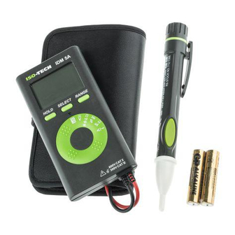
For calibration and repair contact RS Components - the Carry Case Assembling Storage temperature: Warning – For non-contact voltage sensing, do not Carry Case Assembling address is given at the end of these instructions. -20 to +60°C, 0 to 80% RH (batteries not fitted). touch Hazardous Live conductors with the red or black Temperature coefficient: Add 0.2 x (Specified test-probe.
Need help?
Do you have a question about the IDM5 and is the answer not in the manual?
Questions and answers