Table of Contents
Advertisement
Advertisement
Table of Contents

Related Manuals for Iso-Tech IDM 203 RMS


Summary of Contents for Iso-Tech IDM 203 RMS
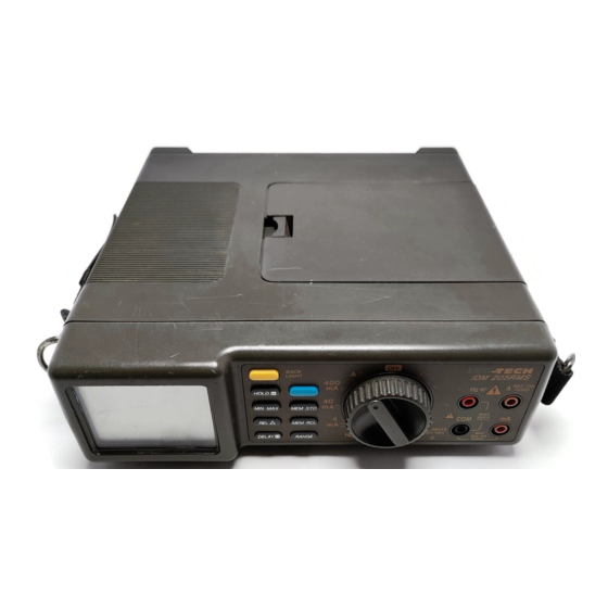
- Page 1 IDM 203/205 RMS DIGITAL MULTIMETER INSTRUCTION MANUAL...
- Page 2 ISO - TECH IDM 203 / 205 RMS Digital Multimeter INSTRUCTION MANUAL...
- Page 4 1. Safety notes These meters have been produced to comply with category II requirements under IEC publication 1010-1, "Safety require- ments for electronic measuring equipment" and with UL 1244. The present operating manual gives directions and warnings which must be observed if the meter is to be used safely and is to be kept in a safe state.
- Page 5 Important : To avoid damage to the meter – Remove the test probes from the item from which measurements are being taken before you change the function to which the meter is set. – Never apply to the meter voltages which may exceed 600Vd.c. or 600Va.c.rms. –...
- Page 6 2. Introduction These meters are mains or battery-powered measuring and testing instruments for service engineers, laboratory use and amateur electronics engineers. The functions they can perform are as follows: Measurement of a.c. and d.c. voltages Measurement of a.c. and d.c. currents Measurement of resistance and capacitance Diode and continuity testing Frequency and ADP measurement...
- Page 7 3. Technical specification 3.1 General characteristics Display : 33/4 digit 4000 count LCD display with a 42-segment analog bargraph display. Higher resolution of up to 9999 in frequency range. Display update rate : Two per second for digital display, 20 per second for bargraph display. For capacitance and frequency measurements: 1 per second.
- Page 8 3.2 Electrical characteristics Accuracy is given as ± (measurement error + display error) and applies at 23°C ±5°C and less than 70% RH. Measurement error (%) is given as a percentage of the current measurement. Display error (D) is given in units equal to the smallest increment able to be shown on the display. Voltage d.c.
- Page 9 Current d.c. current 4mA to 400mA ± (0.75% + 2D) ± (0.4% + 2D) ± (1.5% + 4D) ± (0.8% + 4D) a.c. current 40Hz to 1KHz 4mA to 400mA ± (1.5% + 5D) ± (1% + 5D) ± (2.5% + 5D) ±...
- Page 10 Resistance Range ± (0.75% + 4D) ± (0.4% + 4D) 400Ω 4kΩ, 40kΩ, 400kΩ ± (0.75% + 2D) ± (0.4% + 2D) ± (1% + 3D) ± (0.6% + 3D) 4MΩ ± (2.5% + 5D) ± (1.5% + 5D) 40MΩ Resolution : on 400 Ω...
- Page 11 Capacitance Ranges : 4nF, 40nF, 400nF, 4µF, 40µF Resolution : 1pF on 4nF range Accuracy : see table Input protection : 600Vd.c.or r.m.s. a.c. voltage Range Accuracy (in relative mode) ± (1% + 40D) 40nF ± (1% + 4D) 400nF ±...
- Page 12 4. Using the meter Connecting to mains Important : To avoid the risk of electric shock, it is essential for the earth conductor in the power cable to be linked through to the earth conductor of the mains supply. There are no parts serviceable by the user inside the meter. Repairs may only be made by persons qualified to do so.
- Page 13 6. A Input Terminal — Input for ampere measurement. The meter can measure currents of up to 20A but the time is then limited to a maximum of 30 seconds. 7. Function button (blue) — This button is used to switch between a.c. and d.c., between resistance measurement and continuity testing, and between frequency and ADP measurement.
- Page 14 11. Delay hold button — This button also switches the hold function on, but with a 10 second delay in this case. 12. Manual range button — The manual range button is used to enable the manual range setting facility and to change ranges. If the button is pressed once, the Auto annunciator on the display goes out.
- Page 15 Figure 1 Figure 2...
- Page 16 5. Making measurements Preparatory steps and directions to be followed 1. After you switch the meter on, wait for 30 seconds before you make the first measurement. 2. You must set the desired function with the rotary switch before you bring the probes into contact with the item to be meas- ured.
- Page 17 1. Plug the black lead into the "COM" input terminal of the meter and the red lead into the "V-Ω- " input terminal. 2. Turn the function switch to the "Vd.c." or "Va.c." position. 3. Apply the probes to the source or load whose voltage is to be measured. The polarity of the red probe will be shown along with the measurement.
- Page 18 Continuity testing with the internal sounder 1. Plug the black lead into the "COM" input terminal and the red lead into the "V-Ω- Hz- " input terminal. 2. Turn the function switch to "Ω " and use the function button to set the meter to continuity testing. 3.
- Page 19 Measuring frequency 1. Plug the black lead into the "COM" input terminal and the red lead into the "V-Ω-Hz- " input terminal. 2. Turn the function switch to "Hz ADP" and use the function button to select frequency measurement (Hz). 3.
- Page 20 7. Changing the batteries This meter is powered by a 9V d.c. supply from a transformer-equipped power supply unit or from six 1.5V batteries (AA). To change the batteries, see Fig. 3a and follow the instructions given below. 1. Remove the probes from the item from which measurements are being taken, switch the supply off from the switch at the back of the meter and unplug the test leads and mains lead from the jacks.
- Page 21 Figure 3a Changing batteries...
- Page 22 Figure 3b Changing fuses...
- Page 23 Figure 4 Attaching the carrying strap...
- Page 24 United Kingdom Italy RS Components UK RS Components S.p.A. PO Box 99, Corby Via Cadorna 66 Northants NN17 9RS 20090, Vimodrone, Milano Tel 01536 201234 Tel +39 2/27,425.1 Fax 01536 405678 Fax+39 2/27,425.207 France Germany Radiospares Composants RS Components GmbH Rur Norman King, BP 453 Hessenring 13b 60031 Beauvais Cedex...
Need help?
Do you have a question about the IDM 203 RMS and is the answer not in the manual?
Questions and answers