Table of Contents
Advertisement
Quick Links
Advertisement
Table of Contents

Related Manuals for Iso-Tech IDM-8341 Series


Summary of Contents for Iso-Tech IDM-8341 Series
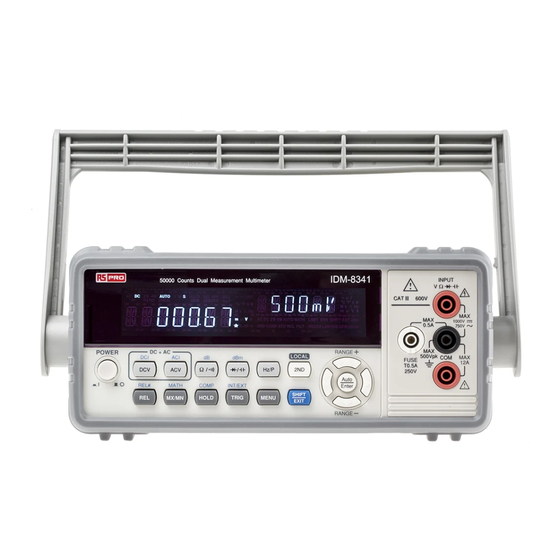
- Page 1 Quick Start Guide Dual Measurement Multimeter IDM-8341/8342 Series...
- Page 2 Limited Warranty This meter is warranted to the original purchaser against defects in material and workmanship for 3 years from the date of purchase. During this warranty period, RS Components will, at its option, replace or repair the defective unit, subject to verification of the defect or malfunction. This warranty does not cover fuses, disposable batteries, or damage from abuse, neglect, accident, unauthorized repair, alteration, contamination, or abnormal conditions of operation or handling.
-
Page 3: Safety Symbols
AFETY INSTRUCTIONS This chapter contains important safety instructions that should be followed when operating and storing the function generator. Read the following before any operation to ensure your safety and to keep the function generator in the best condition. Safety Symbols These safety symbols may appear in this manual or on the instrument. -
Page 4: Safety Guidelines
Safety Guidelines General Guideline • Make sure that the voltage input level does not exceed DC1000V/AC750V. CAUTION • Make sure the current input level does not exceed 12A. • Do not place any heavy object on the instrument. • Avoid severe impact or rough handling that can lead to damaging the instrument. - Page 5 Power Supply • AC Input voltage: 100/120/220/240 V AC, 50/60Hz • The power supply voltage should not fluctuate WARNING more than 10%. • Connect the protective grounding conductor of the AC power cord to an earth ground, to avoid electrical shock. Fuse •...
- Page 6 a reduction of dielectric strength or surface resistivity”. • Pollution degree 1: No pollution or only dry, non- conductive pollution occurs. The pollution has no influence. • Pollution degree 2: Normally only non-conductive pollution occurs. Occasionally, however, a temporary conductivity caused by condensation must be expected.
-
Page 7: Power Cord For The United Kingdom
Power cord for the United Kingdom When using the dual measurement multimeter in the United Kingdom, make sure the power cord meets the following safety instructions. NOTE: This lead/appliance must only be wired by competent persons WARNING: THIS APPLIANCE MUST BE EARTHED IMPORTANT: The wires in this lead are coloured in accordance with the following code: Green/ Yellow:... - Page 8 NTRODUCTION The IDM-8341/ 8342 series quick start guide is intended for users who are already familiar with operating multimeters. This guide is merely a brief introduction to get started quickly. For more details such as setup procedure, parameters, remote control commands, optional scanner, digital I/O, and specifications, refer to the user manual.
- Page 9 ASIC MEASUREMENT AC Voltage Range 0 to 750V Connection Activation Auto range setting Manual range setting...
- Page 10 DC Voltage Range 0 to 1000V Connection Activation Auto range setting Manual range setting...
- Page 11 AC + DC Voltage Range 0 to 1000V Connection Activation Auto range setting Manual range setting...
- Page 12 AC Current Range 0 to 0.5A or 0 to 12A Connection Activation → Auto range setting Manual range setting...
- Page 13 DC Current Range 0 to 2A Connection Activation → Auto range setting Manual range setting...
- Page 14 AC + DC Current Range 0 to 2A Connection Activation → Auto range setting Manual range setting...
- Page 15 Resistance Range 0 to 50MΩ Connection Activation Auto range setting Manual range setting Diode Range Connection Activation...
- Page 16 Capacitance Range 5nF to 50uF Connection Activation Continuity Threshold <5Ω Connection Activation...
-
Page 17: Frequency/Period Measurement
Frequency/Period Measurement Range 10Hz~1MHz Connection Activation Period Measurement Range 1.0μs ~100ms Connection Activation... - Page 18 Temperature Range Thermocouple Connection 200°C ~ +300°C Activation →...
- Page 19 DVANCED MEASUREMENT Advanced measurements refer to measurements that are obtained using one of the basic measurements: ACV, DCV, ACA, DCA, Resistance, Diode/ Capacitance, Frequency/Period, and Continuity. Before an advanced measurement can be made, a basic measurement function must first be selected.
- Page 20 dBm/W Available in Activation → Reference impedance setting Available in Activation → Change voltage range...
- Page 21 Applicable → Activation Applicable → Activation...
- Page 22 Relative Available → Activation Reference value setting Measured value when activated is the reference value Hold Available → Activation...
- Page 23 Compare Available in → Activation Limit setting 1. Enter high Use the Left and Right arrow keys to limit navigate to the digit to be edited, or to select the decimal point. Use the Up and Down arrow keys to edit the selected digit, or to place the position of the decimal point.
- Page 24 4. Confirm setting.
-
Page 25: General Specifications
PECIFICATIONS The specifications apply when the DMM is warmed up for at least 30 minutes and operates in slow rate. Below are the basic conditions required to operate the DMM within specifications: • Calibration: Yearly • Operating Temperature Specification: 18~28˚C (64.4~82.4˚F) •... - Page 26 DC Voltage Accuracy (1 year Range Resolution Full Scale 23˚C ±5˚C) Input Resistance 500mV 10μV 510.00 10MΩ or >10GΩ 100μV 5.1000 10MΩ or >10GΩ 51.000 0.02%+4 11.1MΩ 500V 10mV 510.00 10.1MΩ 1000V 100mV 1020.0 10MΩ * When the input value exceeds the full scale of the selected range, the display will show -OL- (over load) on the display.
- Page 27 AC Voltage, ACV+DCV[3] (AC Coupled) Accuracy (1 year 23˚C ±5˚C) [1] Resolu Full Range -tion Scale 30-50Hz 50-10kHz 10K-30kHz 30K-100kHz 500mV 10μV 510.00 1.00%+40 0.50%+40 2.00%+60 3.00%+120 100μV 5.1000 1.00%+20 0.35%+15 1.00%+20 3.00%+50 51.000 1.00%+20 0.35%+15 1.00%+20 3.00%+50 500V 10mV 510.00 0.5%+15 1.00%+20[2] 3.00%+50[2] 750V 100mV 765.0 0.5%+15...
- Page 28 * The specifications are guaranteed to 10A. A beeping alarm will go off when the input current being measured is higher than 10A. Resistance Accuracy (1 year Resistance Resolution Full Scale Test Current 23˚C ±5˚C)[2] 500Ω 10mΩ 510.00 0.83mA 0.1%+5 [1] 5kΩ...
- Page 29 Capacitance Accuracy (1 year Range Resolution Full Scale Test Current 23˚C ±5˚C) [1] 5nF: 0.5~1nF [2] 2.0%+20 0.001nF 5.100 8.3μA 5nF: 1~5nF [2] 2.0%+10 50nF: 5~10nF [2] 2.0%+30 0.01nF 51.00 8.3μA 50nF: 10~50nF [2] 2.0%+10 500nF 0.1nF 510.0 83μA 5μF 5.100 0.56mA 2.0%+4...
-
Page 30: Temperature Specifications
Current Measurement Sensitivity Minimum Sensitivity (RMS sine wave) Range 30~20kHz 500μA 35μA 0.25mA 50mA 2.5mA 500mA 25mA 0.25A(<2kHz) 10 A 2.5A(<2kHz) Temperature Specifications Accuracy (1 year Sensor Type Measurement Range Resolution 23˚C ±5˚C) Thermocouple -200 ~ +300°C 0.1°C 2 °C * Note: The temperature specifications do not include sensor error. -
Page 31: Declaration Of Conformity
Declaration of Conformity We declare that the below mentioned product Type of Product: Digital Multimeter Model Number: IDM-8342, IDM-8341 are herewith confirmed to comply with the requirements set out in the Council Directive on the Approximation of the Law of Member States relating to Electromagnetic Compatibility (2004/108/EC) and Low Voltage Directive (2006/95/EC). - Page 32 Africa Iso-Tech 1 & 2 Indianapolis Street Kyalami Business Park Kyalami, Midrand, South Africa Asia Iso-Tech 460 Alexandra Road, #15-01A PSA Building Singapore 119963 Europe Iso-Tech PO Box 99 Corby Northamptonshire NN17 9RS United Kingdom Japan West Tower (12th Floor)
Need help?
Do you have a question about the IDM-8341 Series and is the answer not in the manual?
Questions and answers